The learning for this topic will include:
- Explain the purpose and configuration of electric circuit components.
- Explain the operation and characteristics of DC circuits.
- Calculate the resistance, voltage, current, and power and compare with measured values.

What we're covering:
- what 'power' and 'energy' are
- practice exercises
- Raise your right arm above your head slowly. Great – you just consumed about 4 Joules of energy
- Now raise your left arm above your head, but this time do so twice as fast as the first time.
- You have just consumed about the same amount of energy as the first time, but you applied twice as much power since you raised your arm twice as fast.
Energy is the capacity of doing work and power is the time rate of doing work (or delivering energy). To get the same job done repetitively requires the same amount of energy each time, but by applying more power you can get the job done faster.
In physics, energy is defined as the amount of work that can be performed by force, whereas power is defined as the rate or pace of doing work.
The picture represents how energy and power differ. Both the mug and the bottle have water and a flowrate.
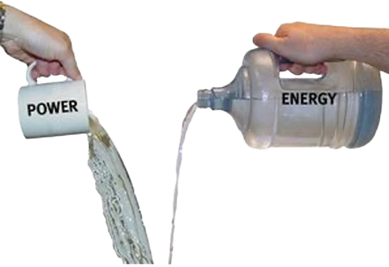
The mug, labelled ‘Power’, has a smaller amount of water, being poured at a greater rate, whereas the bottle labelled ‘Energy’ contains more water, being poured at a slower rate. The mug delivers more water in a given amount of time, but the total amount of water delivered is less than the bottle. The mug has higher power, but lower energy. The bottle releases smaller amounts of liquid for a longer period of time. It has a smaller power output but more energy. The mug releases all its water (energy) very quickly whereas the bottle holds much more water (energy), even if it is not losing it quickly.
Energy comes into our lives in many forms. Since energy ‘cannot be created nor destroyed’ we rely on various devices to convert one form of energy into another. We consume electricity by converting electrical energy to other forms of energy.Energy generated can be stored whereas power cannot. Power also cannot be converted or transformed.
Energy is usually measured in Joules. Power is measured in Watts, which is Joules per second.
You will commonly see power described in Watts and energy in “Watt-hours”. As you apply power (Watts) over a time duration (hours), you will figure out how much energy is consumed in Watt-hours.
It is common for people to use the words “power” and “energy” interchangeably. But you should now know the difference: energy is the total amount of work done, and power is how fast you can do it.
Watch
Take a look at the ‘Slide Energy’
Activity
Work out the answers to questions 1 and 2 below on a piece of paper.
- Two students are lifting weights in the gym. Wiremu lifts the 40 kg barbell over his head 10 times in one minute; Ben lifts the 40 kg barbell over his head 10 times in 10 seconds.
- a.Which student does the most work? (Explain your answer.)
- b.Which student delivers the most power? (Explain your answer.)
- Your household's monthly electric bill is often expressed in kilowatt-hours. One kWh is the amount of energy delivered by the flow of l kW of electricity for one hour. Use conversion factors to show how many joules of energy you get when you buy 1 kWh of electricity.
- Drag and drop the statements that match each quantity.
- Answer the following questions.

What we're covering:
- electric circuits
- circuit symbols
- practice exercises
An electric circuit is a closed-loop network which provides a return path for the flow of electrons. The electric current flows from the source (such as a battery), through the conducting material (e.g., wires and cables), to the load (i.e., light bulb, resistor, diode etc.) before returning back to the source.
Electric circuits can be described in a variety of ways:
1. Using words – e.g. "A light bulb is connected to a D-cell".
2. Drawing – e.g.,

3. A circuit diagram - where conventional circuit symbols are used to provide a schematic diagram of the circuit and its components.

Some commonly used circuit symbols are shown below.

There are around 1750 circuit symbols altogether – this is only a very small sample above!
Note
Some countries use alternative symbols for the same component.
Notice the long line of the cell, or battery, represents the positive terminal and the short line represents the negative terminal.

A straight line is used to represent a connecting wire between any two components of the circuit.
Any electrical device that offers resistance to the flow of charge is referred to as a resistor and can be given this symbol.
A simple circuit comprises the following:
- A power source, including cells and batteries.
- A load or resistor.
- Conductors or wires, connecting the circuit components to the power source to ensure a continuous pathway for current to flow.
- A switch to open or close the circuit.
Activity
Use circuit symbols to construct schematic diagrams on a piece of paper for the following circuits:
- A single cell, light bulb and switch are placed together in a circuit such that the switch can be opened and closed to turn the light bulb on.
- A three-pack of D-cells is placed in a circuit to power a flashlight bulb.
- The diagram below

- The diagram below

Work through a selection of questions from this Simple Circuits Worksheet. Scroll to the end of the worksheet to find answers/useful notes about each question.
Activity
Visit this site and practice building circuits in the virtual lab.
Once you feel confident using the tool, construct the following circuits according to the instructions provided. Fill in the table in this worksheet once you complete each circuit. (Don’t leave it until the end!). When you have completed all six circuits, summarize your findings.

What we're covering:
- series and parallel combinations
- series and parallel circuits
When there are two or more components in an electrical circuit there are a couple of basic ways, we can connect them. They can either be connected in series or in parallel combinations.
A series connection is a connection in which the components of the circuit (resistors) are wired to one another in a single path. The current is the same through each resistor but the voltage around each resistor is not and can be found using Ohm’s Law for that part of the circuit.
A circuit is in parallel when the electric current has multiple paths to flow through. The components that are a part of the parallel circuits will have a constant voltage across all ends. The voltage across each resistor is the same but the current is not and can be found using Ohm’s Law.

The major difference between the two circuits is the amount of current that flows through each of the components in the circuit. In a series circuit, the same amount of current flows through all the components placed in it. On the other hand, in parallel circuits, the current flowing from the source will be split as it flows through each of these components.
For each circuit below, which two devices are connected in series and which two devices are connected in parallel? Note your answers on a piece of paper and check with your tutor next time you are on campus.

Compare electron flow to the flow of cars along a toll way system.

Read
Read the explanation of the Tollbooth Analogy which compares current flow in a circuit to the flow of cars along a toll way system.You can see that adding resistors in series is quite different to adding them in parallel. Adding more resistors in series means that there is more overall resistance; yet adding more resistors in parallel means that there is actually less overall resistance.
| Series | Prallel |
|---|---|
| In an electrical circuit, componens are arranged in line. | In an electrical circuit, components are arranged parallel to each other. |
 |
 |
 |
![[ADD IMAGE'S ALT TEXT]](/sites/default/files/design-team/NZMA3001A/6408/ParallelCircuit.svg) |
| If one component breaks down, the whole circuit will burn out (e.g. a string of Christmas lights). | Other components function even if one component breaks down, each has its own independent circuit ( e.g. power outlets in a house). |
| The current is the same throughout a series circuit. The same amount of current flows through all the components. |
The current flow splits into different paths. The total circuit current equals the sum of the individual branch currents. |
| Voltage across the circuit equals the sum of voltages across each device. Each resistor uses a portion of the total voltage supplied by the battery. |
Voltage in each parallel branch is the same as V source. |
| Adding resistance increases total R. When resistors are put in a series of circuit, the voltage across each resistor is different even though the current flow is the same through all of them. |
The total resistance of a parallel circuit is less than any of the individual branch resistances. Adding resistance reduces total R. |
The equations may be summarised as follows:

Numeracy Check
Calculating total resistance for a parallel can be tricky. Take this circuit for example:

The total resistance of the circuit is given by:

On your calculator press (1/15) + (1/7) = to give you 0.2095238…
and now without clearing your screen, press the reciprocal button
(1/x or x-1) to give you total resistance (R) of 4.77 Ω (2 dec. places)
Now try finding total resistance for this circuit, following the steps above.
You should get 2.14 ohms (correct to 2 decimal places).
Read
Read the information about Series and Parallel Circuits then answer the questions at the end of each lesson.
You may find these questions very challenging! Answers and explanations are provided to assist you but see how far you can get on your own before clicking on them.
What we're covering:
- Course 1 recap
- Measuring voltage
- Measuring current
- Measuring resistance
- Measuring wattage and power consumption
- Practice exercises
Recall from Course One, current can be measured using an ammeter, potential difference (voltage) between two points can be measured using a voltmeter and an ohmmeter can be used to measure resistance.

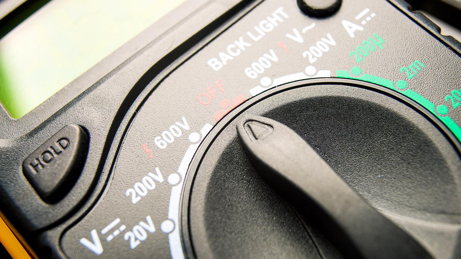
The multimeter is the most important electronic test instrument since it can measure all three of these quantities. There are two types of multimeter - analogue and digital, both having their own advantages. What advantage does the multimeter have over the three meters mentioned above?
Drag and drop each advantage into the correct column.
Activity
Read the information here if you are still a little unsure about using a multimeter.
Connecting instruments in a circuit
Measuring Voltage
A multimeter (or voltmeter) must be connected in parallel with whatever device it is measuring. This is necessary because objects in parallel experience the same potential difference.
The voltmeter calculates the difference in voltage between the two different points (i.e., on different sides of the resistor).
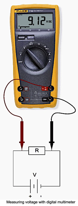
Since voltmeters are connected in parallel, they must have a very large resistance so that they don’t attract any current.
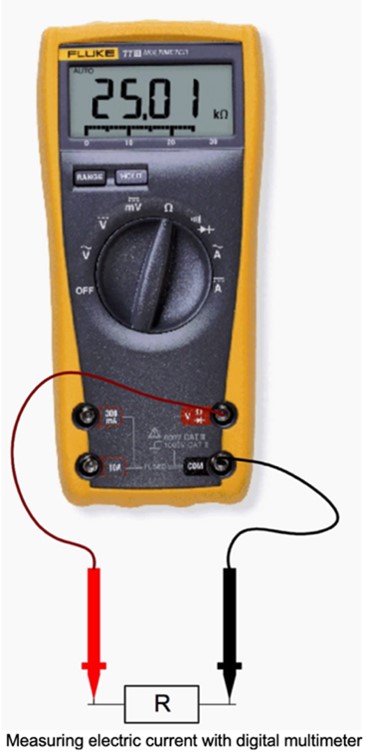
Measuring Current
To measure the current through a device or component, the ammeter (or multimeter) is placed in series with the device or component. A series connection is used because objects in series have the same current passing through them.
When an ammeter is used to measure the current through two resistors connected in series to a battery, a single ammeter is placed in series with the two resistors because the current is the same through both resistors.
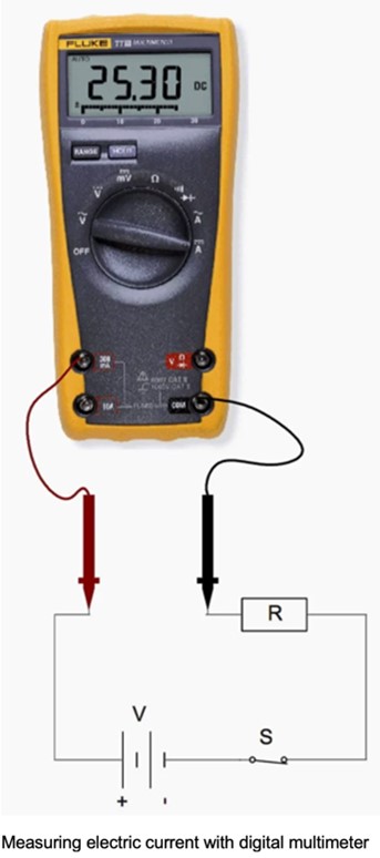
Ammeters must have a very low resistance. If the resistance is not negligible, placing the ammeter in the circuit would change the equivalent resistance of the circuit and modify the current that is being measured.
Measuring Resistance
Note - You can measure the voltage and the current of a live circuit and use those figures to calculate the resistance (using Ohm's Law), but you can't actually measure the resistance of a live circuit. Power should be disconnected before connecting the ohmmeter.
Place a probe tip at each end of the component being measured to measure resistance. Since resistance doesn’t change with the direction of current flow, the positive probe and the negative probe can be on either end of the circuit to get an accurate resistance reading.
Measuring Wattage and the Power Consumption
Watts = Voltage x Current
So, to measure the power in watts of a load or appliance, both the voltage across the load and the current passing through it must be measured. If you have two multimeters, you can measure the voltage and current simultaneously.
Be aware that when any quantity is measured, the measuring device has an influence on the measurement. The resistance of the meter will reduce the current slightly, giving a lower reading than the actual value with the meter not connected.
Activity
For questions 1, 2, 7 and 8, write your answers on a piece of paper. Email your tutor, or take your answers to class to get them checked.
- What do you think might happen if you placed a voltmeter in series with a component to be tested?
- Why shouldn’t you connect an ammeter in parallel with a component?
- Drag and drop the correct words about voltmeters and ammeters.
4. to 6. Complete the following activities about circuits.
7. Most ammeters contain fuses inside to provide protection for both the person using the ammeter, and the instrument. Voltmeters generally do not contain fuses inside, because they are unnecessary. Explain why ammeters use fuses and voltmeters do not.
8. In the circuit shown, the resistances of the resistors are R1 = 100 ohms and R2 = 150 ohms. The supplied voltage is 120V.

- If you connect an ammeter at 1, what current (in Amperes) will the ammeter read?
- If you connect an ammeter at 2, what current (in Amperes) will the ammeter read?
- If you connect a voltmeter at 3, what voltage (in Volts) will the voltmeter read?
- If you connect a voltmeter at 4, what voltage (in Volts) will the voltmeter read?

What we're covering:
- DC cheat sheet
Before we move on to the next section about magnetism let’s recap what we have learnt about DC electricity.
Activity
In this exercise you will create a ‘Cheat Sheet’ about DC Electricity and email the final document to your tutor.
A cheat sheet is NOT for cheating! Cheat sheets are a very valuable way to organise information - concentrating everything you need to know about a particular topic onto the front and back of one A4 piece of paper.
You should not put everything onto your cheat sheet – just the most important things:
- Important information from notes, classwork, extra reading, videos etc.
- Important symbols and formulae.
- Key terms and definitions.
- Key steps to solve a problem.
- Key diagrams or infographics.
- Important theories.
Look at examples of cheat sheets online. You will notice a variety of techniques are used to make the cheat sheet easy to navigate – font size and style, diagrams, columns and boxes to separate information, colour-coding text etc. Then have fun creating your cheat sheet.
HINT - The key areas to focus on are:
- Voltage
- Current
- Resistance
- Power
- Energy (Work Done)
- Series Circuits and Parallel Circuits
- Circuit Diagrams
- Ohm’s Law (and the relationships between the different variables)
Activity
Visit the Virtual Lab site again and build the circuits according to the instructions provided. Refer to your notes about connecting voltmeters in a circuit.
Begin with the simple one-bulb circuit again. With the switch closed, measure and record the voltage drop VBC across the light bulb as shown. Also measure:
- VAB (voltage drop along the wire from +ve battery terminal to the light bulb)
- VCD (bulb back to -ve terminal of battery)
- VDA and VAD (reversing the red and black leads)

Now repeat all the measurements – this time with the switch open. List all your measurements (switch closed and open) the table: you can create one in a word document.
| Reading | Switch closed | Switch open |
|---|---|---|
| VBC | ||
| VAB | ||
| VCD | ||
| VDA | ||
| VAD |
- How are VDA and VAD related?
- How does VAB + VBC + VCD compare to VAD?
- What do you get if you sum up the voltage drops once around the circuit? (i.e., VAB + VBC + VCD + VDA)
- With the switch closed does it appear reasonable to ignore the voltage drops VAB and VCD along the wire segments?
For the series circuit shown, measure the voltage drops across each light bulb and the battery again. Measure VAB, VBC and VCA around the circuit with the switch closed. What is the sum of the voltage drops around the circuit?

For the parallel circuit shown, measure the voltage drop across each bulb and the voltage drop across the battery and record. How do the voltage drops compare?

Make voltage drop measurements across all bulbs for the combined circuit VAB, VBD, VCD and VDA.

From your observations and measurements of voltages in the combined circuit (the final circuit) answer the following questions:
- Find the sum of the voltage drops along path A-B-D (VAB + VBD). Compare this sum to the voltage supplied by the battery, VAD.
- Find the sum of the voltage drops along path A-B-C-D (VAB + VCD). Compare this sum to the voltage supplied by the battery, VAD.
- Research Kirchhoff's Loop rule. How does this relate to the combined circuit above?

What we're covering:
- recap AC and DC
- Amplitude
- Alternation
- Cycle
- Instantaneous value
- Frequency
- Time period
- Waveform
- Peak to peak
- Wavelength
- Root mean square
In Course 2 you learnt a little bit about direct current (DC) and alternating current (AC). Re-read those notes to refresh your memory before continuing.
| Alternate Current | Direct Current | ||
|---|---|---|---|
| Meaning | Current reverses direction at equak time intervals | Current flows in one direction - it is direct - hence its name | |
 |
 |
||
| Abbreviation | A.C. | D.C. | |
 |
 |
||
| Change in Polarity | Change in polarity after a fixed interval. (It is not fixed.) | No change in polarity - it is fixed | |
| Frequency | Frequency depends on country (50Hz in NZ). | Frequency is zero | |
| Current | Varies with time. | Constant magnitude. | |
| Uses |
Power distribution: used to transmit current over long distances without losing power. High voltages are used for power transmission, and then reduced to safer levels for consumers, using a simple transformer - transformers do not work with direct current. High-Power Applications: in homes, factories, and other establishments. |
Batteries: both re-chargeable and non-rechargeable batteries can only store and supply DC. Low Power Electronics: radios, computers, mobile phones, use DC to power the electronic circuits. Equipment powered by AC but will convert AC to DC using a rectifier. Solar panels: produce DC directly from the solar panels themselves. |
|
Common AC Waveform Terms
Amplitude
Amplitude (A) is a measurement of the magnitude or intensity of an AC signal. The amplitude of an AC waveform is its height as depicted on a graph over time. An amplitude measurement can take the form of peak, peak-to-peak, average, or RMS quantity. Peak amplitude is the height of an AC waveform as measured from the zero mark to the highest positive or lowest negative point on a graph. The peaks of the waveform are identified and measured using an Oscilloscope.
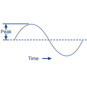 |
One way to way to express the amplitude of an AC quantity is to measure its peak height on a waveform graph. This is known as the peak (or crest) value of an AC wave form and usually shown as Vpk. |
 |
Another way to measure amplitude is to measure the total height between opposite peaks. This is known as the peak-to-peak value of an AC wave form and is usually shown as Vp-p. |
Alternation
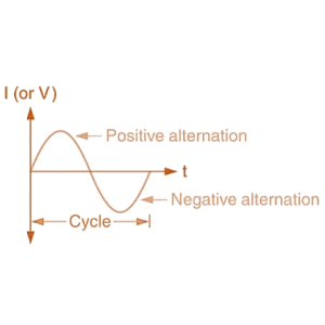 |
The positive and negative halves of the AC waveform are referred to as Alternations. Alternations are defined as a half-cycle since two alternations make up a cycle. |
Cycle
 |
A cycle is a single repetition of back and forth alternating current flow, in other words the complete transition through one positive alternation and one negative alternation. |
Instantaneous value
The magnitude of the waveform at any point of time is called instantaneous value.
The value of voltage or current at any given time quantity is designated by a lower-case letter (either a small e for emf or small v for voltage, and a small i for current).
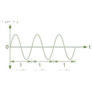
Frequency
Frequency, (ƒ) is the number of times the waveform repeats itself within a one second time period, or the number of cycles completed per second by an alternating quantity.
Frequency is measured in hertz (Hz) or cycle per second (c/s).
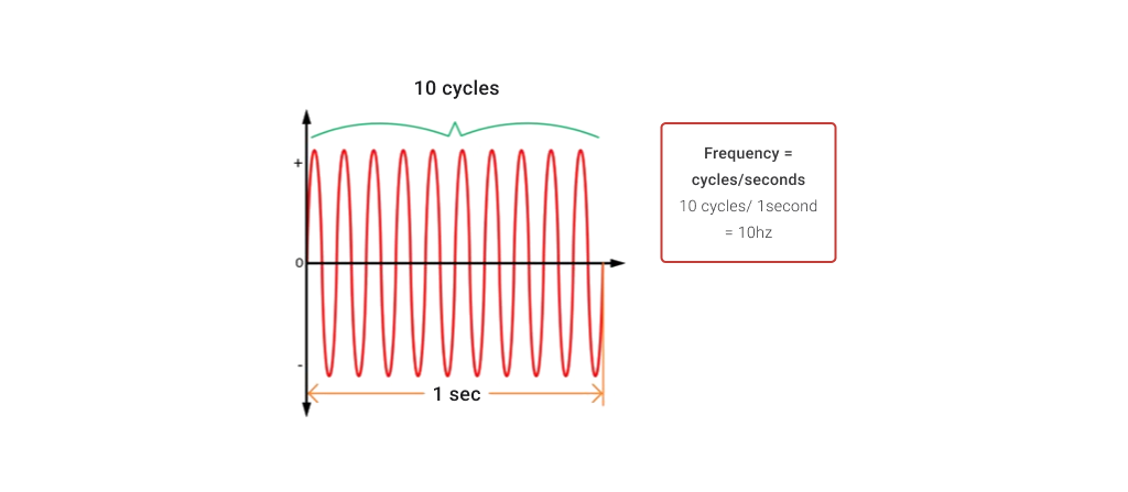
In NZ, the mains supply has a frequency of 50 hertz (Hz) which means it changes direction and back again 50 times per second.
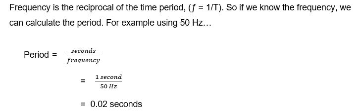
Time Period
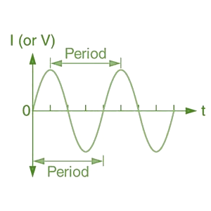 |
The Period, (T) is the length of time it takes in seconds for one complete cycle of the AC signal. The unit of measurement for Period is seconds (s). Period is the reciprocal of frequency, T = 1/ƒ |
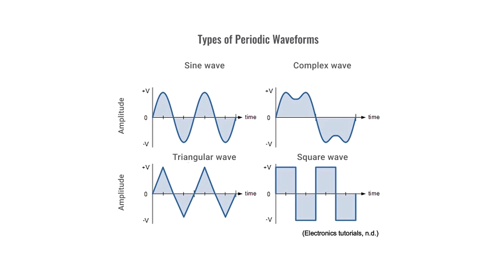
Waveforms
Waveforms are a visual representation of the variation of a voltage or current on the y-axis, plotted against time on the x-axis.
The shape and form of the signal is obtained by plotting the instantaneous values of the quantity.
The most common periodic signal waveforms used in Electrical and Electronic Engineering are the Sinusoidal Waveforms. However, AC waveforms can also take the shape of either Complex Waves, Square Waves or Triangular Waves.
Peak-to-peak
(pk-pk) is the difference between the highest and the lowest values in a waveform. In alternating current (AC) the peak-to-peak value is twice the peak value or 2.828 times the root-mean-square (RMS) value. Peak-to-peak voltage is indicated by VPP.
Wavelength
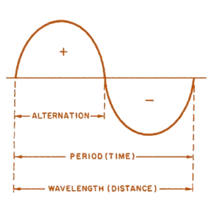 |
Wavelength, symbol Λ (Greek lambda) is the distance along the waveform from one point to the same point on the next cycle. The point on the waveform that measurement of wavelength begins is not important as long as the distance is measured to the same point on the next cycle. |
ROOT MEAN SQUARE (RMS)
In practice both peak (or crest) and peak-to-peak forms of amplitude measurement are rarely used. It is more common to express AC voltage in Root Mean Square (RMS) values or Vrms or Irms.
RMS values define the amount of AC power that produces the same heating effect as an equivalent DC power.
RMS amplitude measurement is the best way to relate AC quantities to DC quantities, or other AC quantities of differing waveform shapes, when dealing with measurements of electric power
RMS voltage can be calculated from peak value, peak-to-peak value, and average value.

You can read more about RMS calculations here if you want to test your numeracy skills.
Activity
- Match the terms to their correct definitions
Determine the following for the waveform shown:
- Determine the following for the sinusoidal waveform shown:
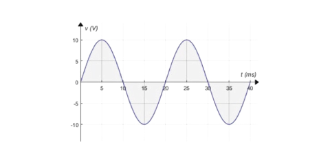
- Peak value.
- Instantaneous value at 15ms and 20ms.
- Peak-to-peak value.
- Period.
- How many cycles are shown?
Activity
Test yourself on this multichoice quiz.
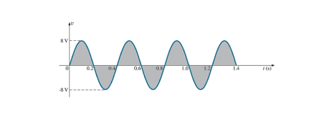
- Peak value.
- Instantaneous value at 0.3s and 0.6s.
- Peak-to-peak value.
- Period.
- How many cycles are shown?
- Frequency.


What we're covering:
- varying the magnetic field
- slip rings
- sine waves
Begin this topic by reading about Electric Circuits on pages 1-3 at the BBC Bitesize site.
AC or DC generators apply the same principle to generate electric current - current will be induced in a conductor inside a magnetic field when there is a relative motion between the conductor and electric field.
There are two ways to vary the magnetic field acting on the conductors - either by rotating the magnetic field around a stationary conductor or spinning the conductor inside a stationary magnetic field. In both cases, an electric current is induced in the conductor.

The AC generator is designed to generate alternating current with a frequency of 50 or 60 Hz. The current induced in the armature is supplied to the circuit using slip rings.
The slip rings are two separate conducting rings connected to each terminal of the armature. They maintain constant contact with the same sides of the coil.
Slip rings supply current to the circuit through a sliding contact called brushes. If we connect two terminals of an external load with these two brushes, we will get an alternating current in the load. Brushes make continuous contact between the external circuit and the slip rings.

Note - the rings always rotate with the armature while the brushes remain stationary.
This video gives a very straightforward explanation of the working principle of AC generator. Watch it a couple of times if necessary to ensure you fully understand the mechanism. Working Principle of AC Generator
Developing the Sine Wave
As the armature rotates, each half cuts across the magnetic lines of force at the same speed. Thus, the strength of the voltage induced in one side of the armature is always the same as the strength of the voltage induced in the other side of the armature. Each half of the armature cuts the magnetic lines of force in a different direction. For example, as the armature rotates in the clockwise direction, the lower half of the coil cuts the magnetic lines of force from the bottom up to the left, while the top half of the coil cuts the magnetic lines of force from the top down to the right. Therefore, the voltage induced in one side of the coil is opposite to the voltage induced in the other side of the coil. The voltage in the lower half of the coil enables current to flow in one direction, and the voltage in the upper half enables current to flow in the opposite direction.
However, since the two halves of the coil are connected in a closed loop, the voltages add to each other. The result is that the total voltage of a full rotation of the armature is twice the voltage of each coil half. This total voltage is obtained at the brushes connected to the slip rings and may be applied to an external circuit.

This diagram shows four different positions of the coil in a simple AC generator, and the potential difference produced at each position.

What we're covering:
- impedance, capacitance and inductance
In a DC circuit the opposition to current flow is called resistance (R) and measured in ohms, Ω.
In an AC circuit, we talk about impedance (symbol Z) which is a combination of both resistance and reactance. Impedance is similar to resistance, but it also takes capacitance and inductance into account.
• Resistance (R) is the slowing of current due to effects of the material and shape of the component. This effect is largest in resistors, but all components have some resistance.
• Reactance (X) is the slowing of current due to electric and magnetic fields opposing changes in the current or voltage. This is most significant for capacitators and inductors.
The magnitude of the impedance Z of a circuit is equal to the maximum value of the potential difference, or voltage, V (in volts) across the circuit, divided by the maximum value of the current I (measured in amperes) through the circuit, or simply:
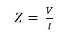
Impedance is measured in ohms, Ω.
Simple AC circuits involving nothing more than an AC power source and resistance, obey the same simple laws and rules as DC circuits. However, AC circuit measurements and calculations become very complicated when we factor in inductance and capacitance.
Measurements of AC voltage and current must be expressed in the same terms (peak, peak-to-peak, average, or RMS). For instance, if the source voltage is given in peak AC volts, then all currents and voltages subsequently calculated must also use peak units, but if the source voltage is given in AC RMS volts, then all calculated currents and voltages should also be in AC RMS units. This holds true for any calculation based on Ohm’s Laws, Kirchhoff’s Laws, etc.
Unless otherwise stated, all values of voltage and current in AC circuits are generally assumed to be RMS rather than peak, average, or peak-to-peak.
This video looks at what happens when a coil is connected to a DC supply and then to an AC supply.
AC Theory: The Mystery of the Coil
Activity
When you have completed the questions below, email or message your tutor to find out how well you did.
- In this AC circuit, the resistor offers 300 Ω of resistance and the inductor offers 400 Ω of reactance. Together their series opposition to alternating current results in a current of 10 mA from the 5 V source.

How many ohms of opposition does the series combination of resistor and inductor offer?
What name do we give this quantity? What is its symbol? - In this AC circuit, the resistor offers 3 kΩ of resistance and the capacitor offers 4 kΩ of reactance. Together their series opposition to alternating current results in a current of 1 mA from the 5 V source.

How many ohms of opposition does the series combination of resistor and capacitor offer?
What name do we give this quantity? What is its symbol? - With reference to the circuit shown answer the following questions:
- What is the reactance XL of inductor L?
- What is the circuit impedance Z?
- What is the supply Current IS?
- What is the voltage VR across the resistor R?


What we're covering:
- dangers of DC power; continuous PV outputs in daylight; stored energy in large batteries.
DC versus AC
Both Direct Current (DC) and Alternating Current (AC), have advantages and disadvantages. DC power, while essential for many applications, presents distinct hazards compared to AC. Some risks associated with DC over AC are listed below:
Muscular Contraction and Tissue Damage
DC has a continuous unidirectional flow of current. When a person comes into contact with a DC source, the continuous current can cause sustained muscular contractions, making it difficult to release from the source of shock. This can lead to prolonged exposure and potentially severe tissue damage.
Higher Voltage Threshold for Perception
In general, humans have a higher threshold for perceiving DC voltage compared to AC voltage. This means that a person may not be aware of a DC shock until it reaches a higher voltage level, potentially increasing the risk of injury.
Electrolytic Effects
DC can cause electrolytic reactions in the body, especially if the current path includes fluids or tissues with varying conductivity. These reactions can lead to the formation of harmful chemicals, tissue damage, and potential long-term health issues.
Difficulty in Breaking the Circuit
DC circuits can be more challenging to interrupt compared to AC circuits. Circuit breakers and protective devices designed for AC may not be as effective in interrupting DC, increasing the risk of electrical fires and other hazards.
Arcing and Welding
When a DC circuit is interrupted, it can lead to arcing that persists longer than in AC circuits. This arcing can cause more significant heat and potentially lead to welding of contacts, which poses a danger to equipment and personnel.

Reduced Availability of Protective Devices
AC systems benefit from well-established protective devices, such as residual current devices (RCDs), that can quickly detect and disconnect the circuit in case of a fault. Similar protective devices for DC systems are less common, making it more challenging to mitigate risks.
Complexity in Isolation
DC systems require additional considerations for isolation due to the potential for sustained current flow. Isolating DC sources can be more complex and time-consuming, increasing the risk of accidental contact during maintenance or repairs.
It's important to note that while DC does carry these increased dangers, proper safety measures, training, and awareness can significantly reduce the risks associated with working around DC sources. Professionals working with any electrical system, whether AC or DC, should be well-informed and follow appropriate safety guidelines to ensure their own safety and the safety of others.
Activity
AC or DC – Defending the Safer Current
Which is safer: AC or DC? Defend your choice between AC and DC by analysing their potential dangers and presenting your argument for why you consider your chosen current to be safer.
Instructions:
- Review the provided information about the dangers of AC and DC electrical currents.
- Choose whether you believe AC or DC is safer based on your analysis.
- Create a list of reasons supporting your choice, focusing on characteristics, effects, and risks.
- Consider factors such as muscular contractions, fibrillation, severity of injury, involuntary muscle spasms, and any other relevant aspects.
- Write a paragraph, defending your choice of the safer current with well-reasoned arguments and clear explanations. Post it to the class forum.
Information:
| Alternating Current | Direct Current |
|---|---|
|
|
Dangers of continuous PV outputs in daylight
Solar Photovoltaic (PV) systems offer clean and renewable energy, generating electricity from sunlight and converting it into direct current (DC) electrical power. While this sustainable energy source has numerous benefits, continuous PV outputs, especially during daylight hours, can result in heightened electric shock hazards.
Dangers requiring careful consideration include:
Electric Shock
Continuous PV outputs generate DC electricity, which can cause electric shock if proper precautions are not taken. Even low-voltage DC can be hazardous if there's direct contact with exposed conductors or faulty wiring. Anyone working on or around PV systems without proper training and safety measures is at risk of electric shock.
Arcing and Fire Hazards
Faults or damage in PV systems, such as wiring issues or equipment malfunctions, can lead to arcing - electric sparks that jump through the air. Arcing poses fire hazards, especially if the PV system is installed near flammable materials. The constant sunlight can exacerbate these risks by providing a continuous energy source for potential faults.
Maintenance and Repair Risks
PV systems require regular maintenance and occasional repairs. The presence of continuous PV outputs means that even during maintenance, there's a potential for electrical generation. This makes maintenance tasks riskier, as technicians must take extra precautions to work safely around live electrical components.
Isolation and Emergency Shutdown
Isolating PV systems for maintenance or emergency shutdowns can be challenging due to continuous daylight generation. In case of emergencies or repairs, shutting down the system completely might involve additional steps, increasing the complexity of isolating the power source.
Unpredictable Faults
Daylight conditions might mask certain faults or malfunctions within a PV system, making them difficult to identify without specialized testing equipment. This can lead to unnoticed issues that accumulate over time, potentially resulting in more significant hazards.
Energy Storage Hazards
Some PV systems incorporate energy storage solutions, such as batteries. Continuous outputs can lead to overcharging of batteries, which can cause overheating, swelling, or even thermal runaway - a hazardous condition that could result in fire or explosion.
Maintenance tasks on live PV systems require specialised training and protective equipment to minimise risks. Additionally, implementing proper protective measures, such as appropriate wiring, insulation, and emergency shutdown procedures, can help reduce the risks associated with continuous PV outputs in daylight.
Stored energy in large batteries
The danger of stored energy in large batteries is a critical consideration in various applications, including renewable energy storage, electric vehicles, and industrial systems. While large batteries offer significant benefits in terms of energy storage and utilization, they also present specific hazards that need careful management.
Understanding these dangers is essential for ensuring the safety of personnel, equipment, and the surrounding environment:
Fire and Explosion Risk
Large batteries store substantial amounts of energy, often in chemical forms that can be highly reactive under certain conditions. If the battery cells become damaged, overcharged, or exposed to extreme temperatures, they can release this stored energy rapidly, leading to fire, explosion, or even the release of toxic gases. The potential for thermal runaway - a self-sustaining, uncontrollable increase in temperature - poses a significant risk.
Overheating and Thermal Events
Intense usage or environmental factors can lead to excessive heat build-up within large batteries. This excessive heat can lead to a dangerous situation called thermal runaway or cascading failures. In thermal runaway, if one battery cell gets too hot, it can make the nearby cells heat up as well. Such events can generate extreme heat and flames, putting nearby objects, people, and buildings at risk.
Chemical Exposure
Batteries often contain corrosive or toxic chemicals. In the event of a breach or damage to the battery casing, these substances can leak or escape, posing a risk to those nearby. Chemical exposure can result in skin irritation, respiratory problems, or other health hazards.
Electrical Hazards
Stored energy in large batteries is released as electrical energy. Accidental short circuits, improper connections, or damaged components can cause rapid discharge of energy, leading to electrical shock, burns, or even fatalities for individuals who come into contact with the system.
Delayed Hazards
Even if a battery appears undamaged, underlying faults or defects can lead to dangerous situations over time. As such, regular monitoring, maintenance, and thorough inspection are essential to detect potential issues before they escalate into emergencies.
Complex Emergency Response
Addressing emergencies involving large battery systems can be challenging due to their unique characteristics and potential hazards. Firefighters and emergency responders require specialised training and equipment to safely manage incidents involving battery fires, explosions, or chemical releases.
To ensure the safe use of large battery storage systems, it's vital to follow safety guidelines, regulations, and best practices. This involves proper battery design, installation, and maintenance, as well as thorough monitoring and management systems. Training personnel, planning for emergencies, and providing protective gear are essential steps to minimise the risks associated with stored energy.
Activity
Watch this video ‘Gas vs electric cars: which is really better?’
Explore the differences between Electric Vehicles (EVs) and Internal Combustion Engine (ICE) vehicles, and formulate a well-reasoned opinion on which type of vehicle you would prefer to buy, considering various pros and cons.
Instructions:
- Review the statements below to get you thinking about EVs and ICE vehicles.
- Gather additional information about the advantages and disadvantages of both EVs and ICE vehicles.
- Consider the environmental impact, cost, maintenance, driving experience, and other relevant factors.
- After conducting thorough research on EVs and ICE vehicles, write a short report explaining which type of vehicle you would choose to buy and the reasons behind your decision. Consider the pros and cons, as well as any additional factors that influenced your choice.
- Post your report on the class forum for discussion amongst your peers.
Statements to consider:
- Electric cars are easier to maintain than gas cars (e.g., no need for oil changes)
- Electric cars produce no tailpipe emissions.
- Electric cars tend to be cheaper than gas-powered cars over time.
- EVs provide less driving flexibility than ICE vehicles due to fewer charging stations.
- EVs have a higher initial purchase cost than an ICE vehicle.
- Electric cars rely on lithium, which faces a global shortage that could impact battery maintenance.
- The environmental friendliness of electric cars depends on the source of electricity used for charging.