
Drawing conventions
To read and interpret plans, you need to know about certain drawing conventions applied in the construction plans. These drawing conventions are the following:
Datum and reduced levels
In construction, a datum can be an arbitrary horizontal plane or a point outside or within the property, either real or imaginary, used as a reference for all vertical measurements made in the construction project. These vertical measurements based on the datum are referred to as reduced levels (RL).
In construction drawings, datum can be established by:
- Setting the datum at the building's ground floor will be considered as 0.0 metres elevation. This means that all elements found above the datum (e.g. second floor level) will have a ‘positive’ elevation (e.g. + 3.2 metres), and all elements found below the datum (e.g. basement floor) will have a ‘negative’ elevation (e.g. -3.0 metres).
- Setting the datum at the lowest part of the building (e.g. basement) will be considered as 0.0 metres elevation. This means that all other elements, excluding foundations, will have a ‘positive’ elevation.
- Setting the datum at a location found outside the project site (if the project is large), for instance, the Australian Height Datum.
On the other hand, RLs can be established in construction drawings by:
- Using positive and negative symbols to indicate whether the reduced level is above or below the reference point, respectively (e.g. +3.5 metres or -3.5 metres); or
- Explicitly stating whether a reduced level is above or below the reference point (e.g. 1 metre above RL 2.5 metres or 1 metre below RL 2.5 metres).
Datum and RLs are usually seen on the site and floor plans of the building project, but RLs are also indicated (with a different drawing symbol) on sections and elevations as well.
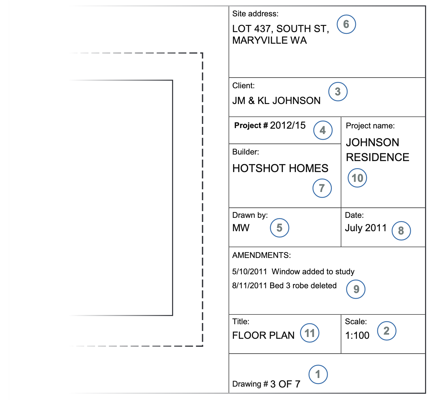
Title block
A title block is a portion on the drawing sheet that provides general information about the drawings (e.g. who, what, when, and where, etc.) and specific information about the particular drawing sheet. It is usually located at the bottom portion or at the sides (usually the right-hand side) of the drawing sheet.
The types of information you can obtain from title blocks include, but are not limited to, the following:
- Name of architect/engineering company
- Project title
- Project site address
- Name of draftsperson(s)
- Date of publication
- Amendments/revision
- Scale
- Sheet number
- Client name
- Type of drawing
Below is an example of a title block:
Scale
Scale refers to the ratio that dictates the size of scale drawings, which are drawings used for accurately illustrating real-life building components or items at fixed, reduced, and enlarged sizes. These scale drawings can be measured with a scale rule to determine their actual size. However, you can immediately obtain the actual size of the real-life object when you use computer-aided design.
Scales are especially significant in illustrating the drawing so that the details of the object are captured and ensuring that the object fits in the drawing sheet.
The table below shows some examples of the ratio of standard scale ranges and their corresponding description.
| Ratio | Description |
|---|---|
| 1:100 |
|
| 1:2 |
|
| 1:1000 |
|
| 1:50 |
|
Dimensions
Dimensions are numerical values expressed in units of measurement, which are important in defining the size and other measurements of an object, including length, width, height, thickness, and the like.
In construction plans, the metric system is usually used (unless otherwise indicated) since Australia uses the metric system. Thus, you can see in the plans that, typically, the units metres (m) and millimetres (mm) are used to define the dimensions. However, there are cases when these units of measurement are not indicated in the plans. Still, this should not be a cause for confusion since the presence of decimal points or commas, or the numerical value itself, imply what unit of measurement (i.e. whether millimetre or metre) is being used.
Below are ways of how dimensions can be displayed in construction drawings:
- Using decimal points. In some cases, decimal points may be used in displaying the dimensions of certain objects. Values may be rounded off to either two or three decimal places. (e.g. 2500.00 or 2500.000)
- Using comma or space as a thousand separator (e.g. 2 500 or 2,500). However, you may opt not to use this as there are many cases wherein values are displayed without a comma or space.
- Using dimension terminators such as dots, arrowheads, or slash to indicate which point the measurement starts or ends.
As in the example below, the dimensions utilise extended lines and slash to indicate the starting and ending points of the measurement. They do not use commas as a thousand separator and decimal points (i.e. rounded off to whole numbers).
In some cases, building components are not drawn with dimension lines and terminators but are displayed in the ‘length x width x height’ format. For example, one concrete hollow block (CHB) may be displayed as 230 x 110 x 76.
Abbreviations
Abbreviations are shortened forms of common construction terminologies. These are frequently used in construction plans to allow the designer or drafter to save drawing space. Additionally, it takes less time to display abbreviations when labelling construction components in drawings.
Below is a table of common construction terminologies and their corresponding abbreviations.
| Area of Construction | Terminology | Abbreviation |
|---|---|---|
| Architectural | Downpipe | DP |
| Plasterboard | PB | |
| Kiln dried hardwood | KDHW | |
| Structural | Wall tie | WT |
| Rectangular hollow section | RHS | |
| Universal beam | UB | |
| Mechanical | Air conditioning unit | ACU |
| Fan coil unit | FCU | |
| Access panel | A/P | |
| Electrical | Main switch board | MSB |
| General power outlet | GPO | |
| Residual current device | RCD | |
| Plumbing and drainage | Water closet | WC |
| Polyvinylchloride Pipes | PVC Pipes | |
| Urinal | U |
Building and construction standards
Complying with standards is one way to achieve compliance with government minimum requirements set out in the National Construction Code (NCC). In addition, standards serve as concrete examples of best practices that can then be used to model what needs to be done in a building and construction project. They serve as thresholds that the project must meet to achieve safety and achieve sustainability and proper functionality. These standards will be used to assess the completed building as well, so referring to them during the construction phase means greater chances of passing these assessments.
As construction personnel tasked with reading and interpreting the plans, it is important to know and understand the standards that serve to prepare and create construction drawings. These are:
-
Dimensions AS 1100.101-1992 – Technical drawing - General principles. This standard sets out the basic principles of technical drawing practices. It covers essential abbreviations, materials, sizes, and layout of drawing sheets, requirements for distinct uniform letters, numerals, and symbols, recommended scales, how they are applied, etc. You can access a sample of the standard at the Additional Resources, at the end of the module.
-
AS ISO 128.20-2005 – Technical drawings - General principles of presentation, Part 20: Basic conventions for lines. This standard contains general rules for the presentation of lines in all kinds of technical product documentation, including preparation of lines by CAD systems, basic conventions, and applications for leader lines and reference lines, lines on construction drawings, etc. You can access a sample of the standard at the Additional Resources, at the end of the module.
Workplace processes
You must note that the plans and specifications you will read and interpret depend on your organisation's work processes. Some of these aspects include:
-
Types of plans your workplace produces. For example, if you are working for an architectural firm, the plans available are most likely architectural plans and specifications. This means that the plans for other construction areas (e.g. structural, mechanical, plumbing) will be sourced from other industry designers such as structural designers, plumbing engineers, electrical engineers, etc.
-
Process for creating building construction plans. The process for creating building and construction plans highly affect the currency of the plans. For example, when incorporating changes in the design, you have to check whether those changes are reflected in the plans. You must be aware of the process for doing any rectification works to account for any possible delays.
-
Software used in creating building construction plans. Especially in the age of technology, there will be times when you will not be using paper blueprints to read plans. Instead, you will be utilising computers and drawing software in reading and interpreting plans.
Some examples of construction drawing software include AutoCAD, Revit, ArchiCAD, and Sketchup. The function and interface vary, depending on the software to be used. Therefore, you must note what software your workplace is using so you can familiarise yourself with that software.

Distinguishing key features on the plans involves picking out the unique details or features in each type of construction plan to differentiate one plan from the other. This will help you identify which type of plan to refer to when looking for specific details about the building project.
Take note that the key features stated in the table below are what can be generally seen in indicated construction plans. The key features vary from project to project.
| Type of Plan | Key Features |
|---|---|
| Concept drawing/sketches |
|
| Architectural |
|
| Structural |
|
| Civil | (Same as architectural plans and structural plans) |
| Mechanical |
|
| Electrical |
|
| Plumbing and draining |
|
| Utilities and services |
|
Take note that there may be features in other construction plans not stated in the table above.
As an example, if you need to identify the sanitary fixtures of a specific floor for a building project. Having familiarised yourself with the key features of each type of plan, you can say that the information you need is contained in the plumbing and draining plans and not on other plans. If you are looking to find out the sizes of footings, you can say that the information you need is contained in the structural plans since these plans contain the footing schedule (schedule of materials).
Distinguishing the key features of the plans is essential, especially since you will be dealing with 2D and 3D drawings in reading and interpreting information from the different types of plans. In addition to that, it is essential in doing the following workplace tasks:
- Estimation: The interpretation of 2D and 3D drawings can be used in doing estimation tasks. This includes identifying the dimensions such as length, width, height, thickness, etc. of the building and its components and calculating the quantities of the necessary building components.
- Planning: In the planning phase of the construction project, you can present your findings in your interpretation of the information from the plans. This includes discussing the building components and items, as well as their corresponding sizes and quantities. It is also important in establishing details to be used as the basis in the construction or implementation phase.
- Supervision: During the construction or implementation phase, there are tasks that you need to supervise. Including, but are not limited to, the following:
- Installation of cabinetry and appliances (e.g. oven, refrigeration, dishwashing)
- Erection of walls (e.g. brick, panels, framing)
- Installation of tiles (e.g. wall tiles, floor tiles)
In such tasks, you need to refer to the details discussed from the planning phase, such as the correct sizes and configuration of building components and the correct quantities.
Building location
The site plan provides an overview of the entire property. It shows all site elements to be considered in the construction of a building and gives an idea of the entire scope of work involved in the project. One of the details included in this plan is the location of the building.
Identifying the building location is important since it defines the state or territory requirements that the building and construction project must follow. Also, it is important in guiding relevant construction personnel in accessing the site in cases where site visits or inspections need to be conducted.
In identifying the building location, you may take note of the following questions to guide you:
- What is the exact location of the building project?
- What is the street number/ block number/ title number of the block of land where the building is to be constructed?
- What is the name of the road adjacent to the block of land?
- What are the properties adjacent to the block of land where the building is to be constructed?
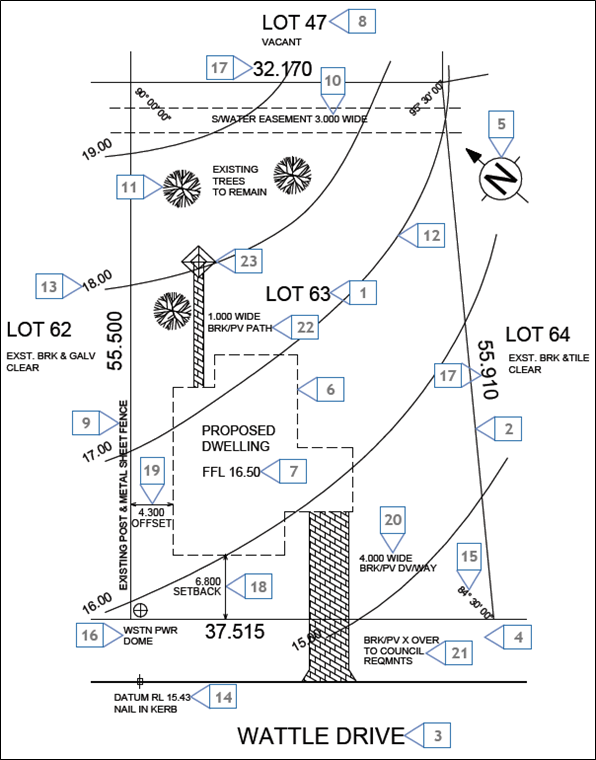
To answer the first question, the building's exact location can be seen in the title block of the site plan. Refer to the example below:

The text inside the red box is the location of the building project.
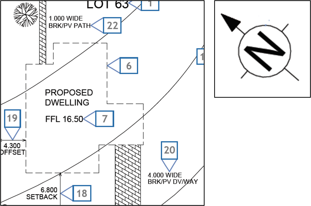
To answer the next questions, a sample site plan2 will be used. Note that the image is labelled with coloured boxes for reference.
Based on the site plan, the block number of the land where the building is to be constructed is Lot 63.
The name of the road adjacent to the block of land (specifically at the front of the land) is Wattle Drive.
The properties adjacent to the block of land where the building is to be constructed is Lot 62, Lot 64, and Lot 47.
Other elements in the site plan
Apart from the building's location, other elements can be found on the site plan. These are the following:
- Orientation of structures
- Site contours
- Datum and reduced levels
- Site features to be removed or retained.
Orientation of structures
In identifying the structure's orientation, you can look at the site plan and compare it with the direction of the north point or north arrow.
The front face of the building (the section facing the road), is oriented in a south-west direction.
Site contours
Site contours refer to the outline of the profile of the land. These are usually derived from a detailed survey done by a surveyor. These contours are represented in the site map through contour lines. Contour lines are imaginary lines that connect points of equal elevation on the site. Contour lines are based on an arbitrary datum or reference of elevation.
The outline of the profile of the land can be described in the physical features listed below:
- Flat surfaces are represented by widely spaced contour.
- Steep ground is represented by closely spaced contour.
- Uniform slope is represented by equally spaced contour.
- Uneven surfaces are represented by irregular contours.
- A pond is represented by approximately concentric closed contours with decreasing values towards the centre.
- Hills are represented by approximately concentric closed contours with increasing values towards the centre.
- Ridges are represented by contour lines with U-shape with convexity towards lower ground.
- Valleys are represented by contour lines with V-shaped with convexity towards higher ground.
- Contour lines generally do not meet or intersect each other. However, if they intersect at a common point, it indicates the presence of vertical cliffs. If contour lines cross each other, it indicates the presence of an overhanging cliff or a cave.
To illustrate an example of identifying site contours, the site plan image from the previous topic will be used. According to the site plan, the upper left portion (back of the property) records an elevation of 19.00. The succeeding contour lines are equally spaced from each other (at one-metre intervals) until it reaches a contour line elevation of 15.00 towards the lower right (front of the property) of the plan. This means the profile of the land is uniformly sloping down from the rear-left corner to the front-right corner of the property.
Datum and reduced levels
As discussed previously, datum can be an arbitrary horizontal plane or a point outside or within the property, either real or imaginary, that is used as a reference for all vertical measurements made in the construction project. These vertical measurements made are referred to as reduced levels (RL).
The datum and reduced levels can be identified easily in the site plan since they are labelled as such. Using the same site plan from earlier, the datum for the site is shown below.
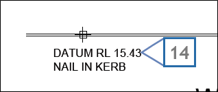
Based on the image, the datum is at an elevation of 15.43. Note that the datum is labelled with RL, meaning that it is also a reduced level. This tells you that the datum was established based on another point or plane of reference, making the datum a reduced level. Additionally, the contour elevations in the site plan are considered reduced levels (RL) since they are all based on the datum specified above.
Site features to be removed or retained
Included in the site plans are site features to be removed or retained. Identifying site features to be removed or retained is significant in the construction phase since it tells the builders of any additional scope of work (e.g. demolition) involved.
The site features include trees, shrubs, debris, fences, and others which are specified in the site plan as to be retained or removed. Using the same site plan as an example, you can see that the existing trees in the property are specified as features to be retained when the construction is finished.
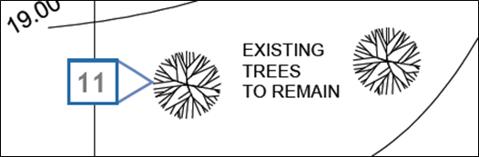
For this site plan, no features are specified to be removed. However, site plans for other construction projects specify if there are features to be removed. Like site features to be retained, site features to be removed can be identified in the site plan by referring to the labels. Features to be removed may be labelled with something like ‘Existing structure for removal’.
State and territory requirements
As mentioned, identifying the building location is essential since it defines the state or territory requirements that the building and construction project must follow. The discussion below will discuss the different state or territory workplace safety requirements, environmental requirements, and other building and construction regulations.
Workplace safety
Workplace health and safety aims to uphold the protection of the health and safety of workers at work and others who might be affected by the work. Refer to the table for the WHS Acts for each state and territory.
| State/Territory | WHS Act |
|---|---|
| Australian Capital Territory | Work Health and Safety Act 2011 |
| New South Wales | Work Health and Safety Act 2011 |
| Northern Territory | Work Health and Safety (National Uniform Legislation) Act 2011 |
| Queensland | Work Health and Safety Act 2011 |
| South Australia | Work Health and Safety Act 2012 |
| Tasmania | Work Health and Safety Act 2012 |
| Victoria | Occupational Health and Safety Act 2004 |
| Western Australia | Occupational Safety and Health Act 1984 |
Environmental requirements
Environmental requirements are requirements that a building and construction project must follow to address construction-related issues and problems that pose risks to the environment. Refer to the table below for the environmental acts for each state and territory. While this list may seem extensive, it is your responsibility to check for applicable acts and regulations governing your activity.
Building and construction legislation and regulations
Government building and construction legislation and regulations contain provisions for matters related to building design and structural integrity and contracts, licences, registration, and other building legalities.
Below is a table showing government legislation and regulations related to building and construction in each state/territory.
| State/Territory | Legislations/Regulations |
|---|---|
| Australian Capital Territory | |
| New South Wales | |
| Northern Territory | |
| Queensland | |
| South Australia | |
|
Tasmania |
|
|
Victoria
|
|
|
Western Australia |

Building layout
Building layout refers to how the building and its components are set out or arranged. Additionally, it refers to the exact position and orientation of the building. When reading floor plans, the building layout is the first and most obvious aspect. The floor plan shows the outline of the building and its shape.
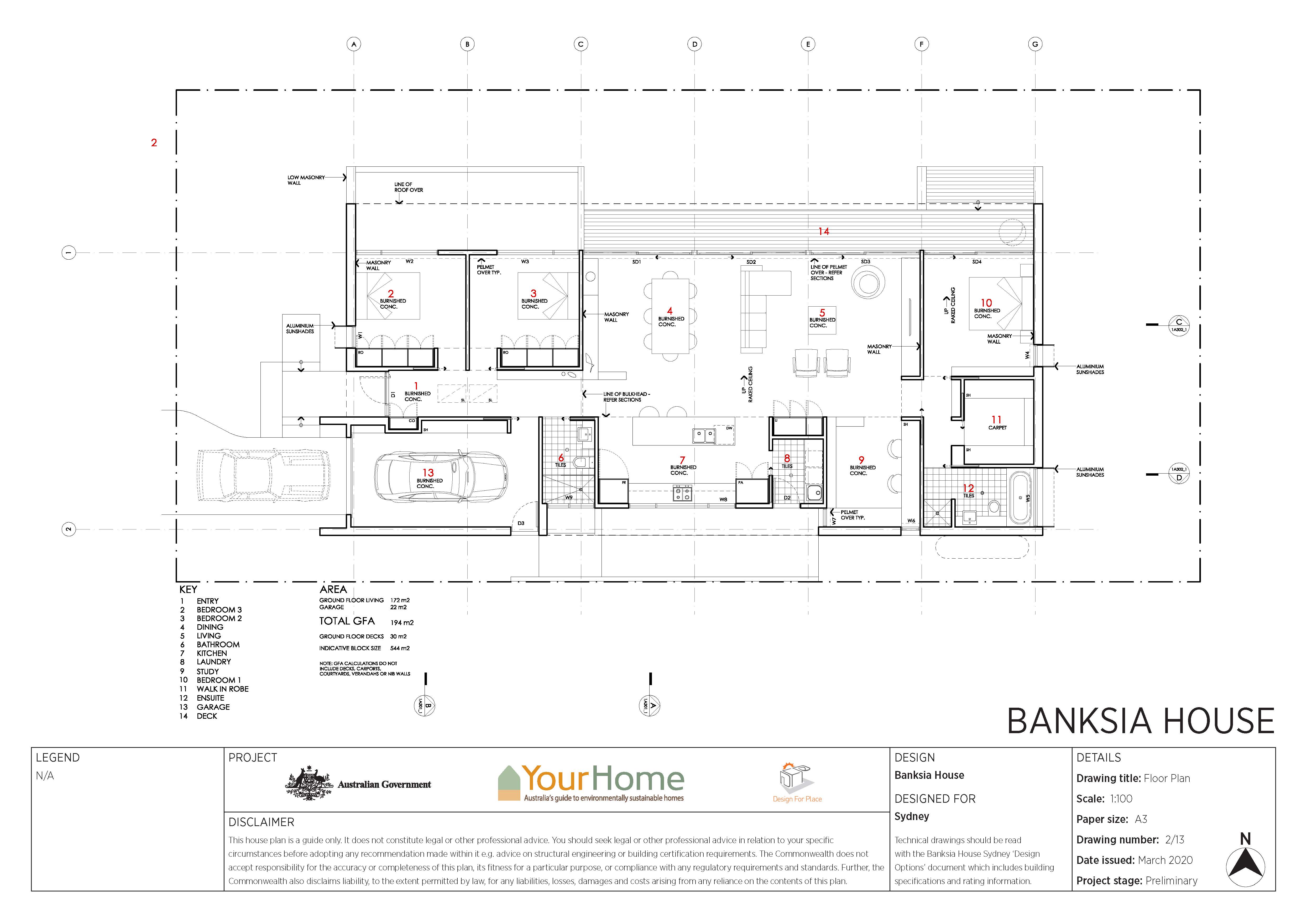
The previously used building design of the Banksia House will be used as an example. As you can see in the plan, the building layout of the building project is straightforward. The shape of the building is almost a perfect rectangle, with one side containing most of the shape irregularities. Additionally, based on the floor plan, you can see the arrangement of interior elements such as furniture, fixtures, appliances, etc. By looking at this, you will have an overview of the function and feel of the building.
Building spaces
Building spaces refer to the divisions or areas in the building provided for specific purposes or activities. In a residential building, basic spaces include the bedroom, kitchen, living room, toilet and bath, dining area, and garage. However, in commercial buildings, additional spaces may be required to accommodate activities such as fitness, arcade rooms, control rooms, and others.
In identifying building spaces, you need to look for labels or legends that correspond to a building space. In some cases, labels are placed directly over the building spaces for easier identification.
Using the Banksia House floor plan, you can see that numbers coloured in red are placed over the building spaces. The legend at the lower-left corner of the sheet contains the functions of the building spaces corresponding to the red-coloured number labels. Number 2 building space is used as a bedroom (Bedroom 3), and Number 13 is used as a garage.
Identify building dimensions
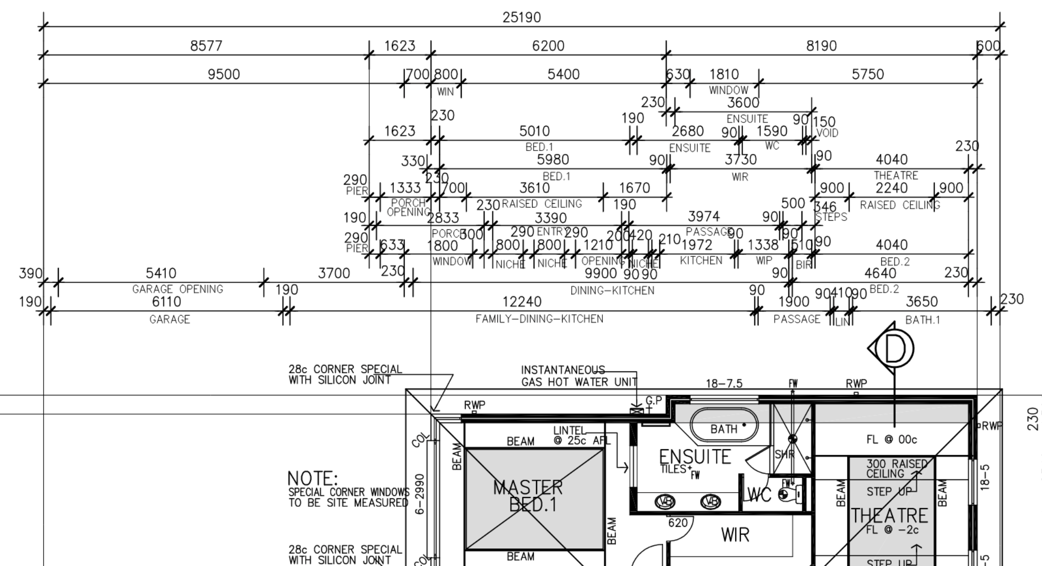
Building dimensions refer to the measurements of the building perimeter and the measurements of the individual spaces or rooms contained in it. These dimensions consist of extended lines with arrows, setting the limits or extent of the measurements, and are at the sides of the building outline. The image below is another example of a floor plan3.
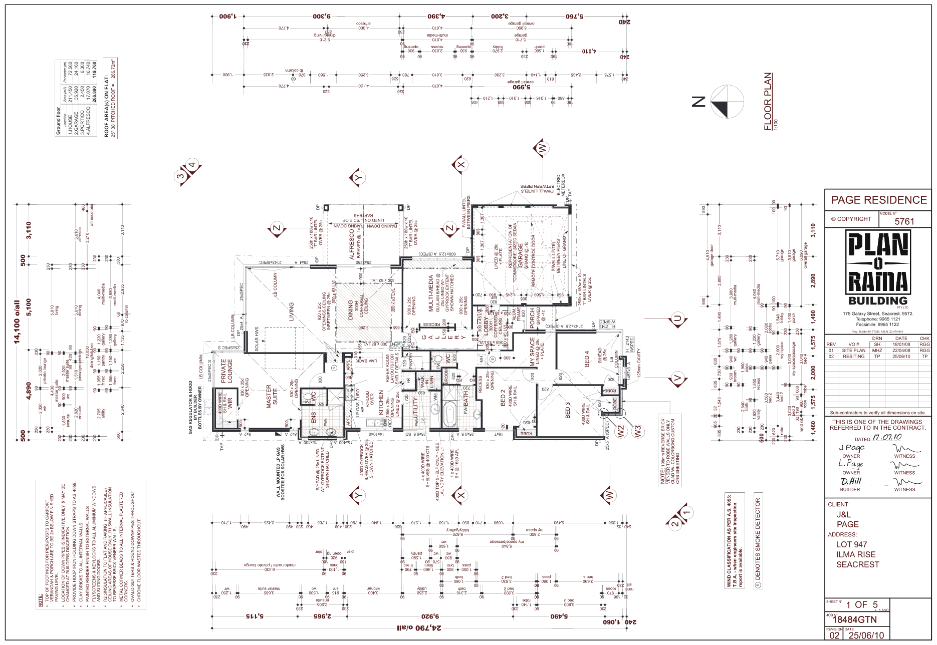
In identifying building dimensions, you need to trace the extended lines and take note of the arrowheads that dictate when a measurement begins or ends. You may use a ruler or any straightedge to help you with this.
An essential aspect of dimensions that you must note is the unit of measurement. Australia uses the metric system. However, you must always double-check the system measurement used in the plan.
For example, based on the floor plan sample, the square garage has a right-side length of 5,990 mm and is 6,090 mm (including both garage door and walls at opposite ends) on the other side. On the other hand, the room for multi-media has its right side measuring 4,070 mm and measurement of 3,980 mm on the other side.
Detail drawings provide large scale views of parts or components of a building. Examining detail drawings is important when analysing intricate details and any complex configuration since this allows you to determine the specifications of building components such as sizes and thickness and the corresponding methods of construction or installation processes.
In examining detail drawings, you need to look at the corresponding dimensions of the building component. These dimensions provide the necessary measurements such as size, thickness, diameter, etc.
Additionally, while examining detail drawings, you must also note down the corresponding labels or brief textual descriptions. These labels or textual descriptions contain the building component specifications which may include sizes and thickness of components and the necessary construction methods.
To illustrate this, refer to the detail drawing image4. This image is a sample detail drawing of a specified column.

Based on the image above, the pad footing (labelled PF4) is specified to have a size of 1000 x 1000 mm, with a thickness of 350 mm (refer to numbers 4 and 5). You could also see the thickness of the slab-on-ground, which is specified to have a thickness of 125 mm and increases to 200 mm upon resting on the pad footing (refer to number 1).
You can also determine the methods of construction, for example, the text near the number 2 tells you that paintworks or coating works are involved in footing construction. Additionally, the dimensions near the number 3 tells you that the bottom of the pad footing needs to be at least 400 mm below ground level. Thus, excavation work is required.

There are many more methods of construction that can be determined from detail drawings and the different parts of the plan. Since construction methods refer to the different construction activities or jobs necessary for the completion of a building, these construction methods vary from project to project. Below are methods of construction you usually encounter when reading and interpreting plans:
- Paintworks or coating works – refer to the application of paint or coating to materials
- Earthworks – refer to construction methods such as the excavation and compaction of soil
- Concrete works – refer to methods related to the construction of concrete building elements (e.g. post-tensioning, concrete pouring, installation of forms, etc.)
- Steelworks or reinforcement works – refer to the methods related to the construction of steel building elements (e.g. welding, tie-down installation, rebar cutting, etc.)
- Carpentry works – refer to the methods related to the application of wooden materials or structures (e.g. roof truss installation, timber wall framing installation, etc.)
- Tile/brick/block work – refers to the application of elements such as tiles, bricks and other masonry units
Many details can be identified from the plans and specifications, such as internal linings, external cladding and roof materials.
Plans
In identifying internal linings and external cladding, you need to refer to the floor plans (usually architectural floor plans) and wall or ceiling detail drawings of the building project. To illustrate this, refer to the sample detail drawings of a brick wall.
Based on the brick wall details5, the internal linings used for the internal leaf of brickwork (BWK) is plaster finish (refer to number 1). The external cladding used for the walls is specified to be ‘Hardies Scyon 150 Linea W/Boards’, which is a type of weatherboard (refer to number 2).

In identifying roof materials used for the building project, you may refer to the architectural or structural plans and the roof detail drawings. To illustrate this, refer to the sample detail drawing of a roof.
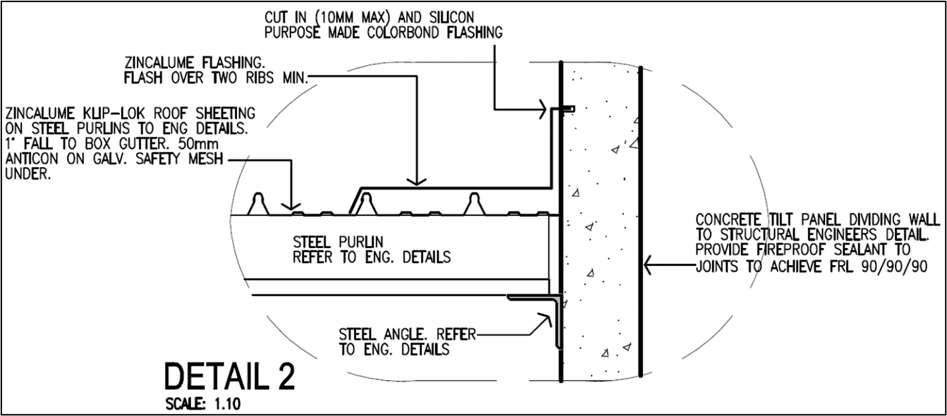
The image labelled ‘Detail 2’ is one of the several detail drawings for the particular building and construction project. The labels and the arrows in the image tell you the materials needed for the construction of the roof. These are the following:
- Zincalume flashing
- Silicon purpose-made Colorbond flashing
- Zincalume Klip-Lok roof sheeting
- Steel purlins
- Steel angle
Note again that this is only one of the several detail drawings. You must check other detail drawings to identify all roof materials for the building project.
Specifications
Internal linings, external cladding, and roof materials may also be identified from the specifications document for the building project. To illustrate this, refer to the sample specifications6.
Refer to the ‘contents’ page of the document. As you can see, you can refer to Part L ‘Plasterer & Tiler’ to identify internal linings (specifically, plaster), Part E ‘Brickwork’ to identify external cladding (specifically, bricks), and Part I ‘Roofer’ to identify roof materials.
The image below shows Part L ‘Plasterer & Tiler’ of the specifications document. As you can see in this section of the specifications document, the internal walls are specified to be plaster smooth float and set. On the other hand, internal ceilings are specified to be Gyprock.

The next image shows Part E ‘Brickwork’ of the specifications document. As you can see in this section of the specifications document, bricks used as external walls are specified to be Maxi or Verticor with painted render.

This image shows Part I ‘Roofer’ of the specifications document. As you can see, specifications for the main roof covering and roof insulation are stated here. For the main roof covering, Colorbond sheet metal roofing is to be used with a 30° pitch. The roof insulation is to consist of sarking to the underside of roof sheeting with ceiling insulation according to the energy assessors' requirements.