
The National Construction Code (NCC) sets out the technical provisions for the design, construction, and performance of buildings and plumbing and drainage systems. It is important to remember that the NCC requirements must be reflected in the construction drawings during the planning stage (i.e. drawings and sketches) must show that the design, materials, or construction meets the relevant Performance Requirement or Deemed-to-Satisfy (DTS) Provision.
The NCC is divided into three volumes. Refer to the table below for the corresponding description of the volumes. Note: the NCC volumes are available online upon free registration on NCC's website.
| Volume | Description |
|---|---|
| NCC Volume 1 | Volume One7 contains technical design and construction requirements for all Classes 2 to 9 buildings (multi-residential, commercial, industrial, and public assembly buildings) and their associated structures. |
| NCC Volume 2 | Volume Two8 contains technical design and construction requirements for certain residential and non-habitable buildings and structures, specifically Class 1 and Class 10 buildings. |
| NCC Volume 3 | Volume Three9 contains technical requirements for designing and constructing plumbing and drainage systems in new and existing buildings. |
All aspects of the building, including structural details, must comply with the NCC requirements, which are:
- General Requirements: Also known as Governing Requirements, the General Requirements contain the rules and instructions for using and complying with the NCC. They serve as a guide in understanding how the technical requirements should be applied to any particular situation.
- Performance Requirements: These are requirements that state the minimum level of performance for buildings and plumbing and drainage installations. These requirements can be achieved through compliance options, such as performance solutions, deemed-to-satisfy solutions, or a combination of both.
Classes of buildings
You must note that the building requirements, including the structural requirements, depend on the classification of the building. As discussed earlier, NCC Volume 1 covers the technical design and construction requirements for Classes 2 to 9 buildings, while Volume 2 covers the technical design and construction requirements for Classes 1 and 10 buildings.
The classes of buildings are based on the National Construction Code. Refer to the table below for a summary of the classes of buildings and their descriptions.
This 5-minute video explains NCC and how it classifies buildings:

Concrete footing, slab details and the requirements for reinforcement are shown on the plans and detail drawings. Footing is an essential and critical part of a structure. Footing transmits the superstructure load (i.e. loads from roof, beams, floors, columns, and walls) down towards the soil foundation. They serve as the ‘feet’ of the building and must be designed and constructed to ensure that the building can stand against external forces.
While concrete slab can be used for suspended floors (e.g. second or third floors), they can also be used as footings, as in a concrete slab floor. Slab footings resist gravity loads, such as the weight of tiles, partitions, and people, as well as lateral loads from earthquakes or typhoons.
Identifying concrete footing and slab sizes, position and type of reinforcing are essential for creating project cost estimates as these aspects are major factors that greatly affect the cost of the entire project.
Concrete footing
In identifying the concrete footing position, this plan10 will be used as an example:
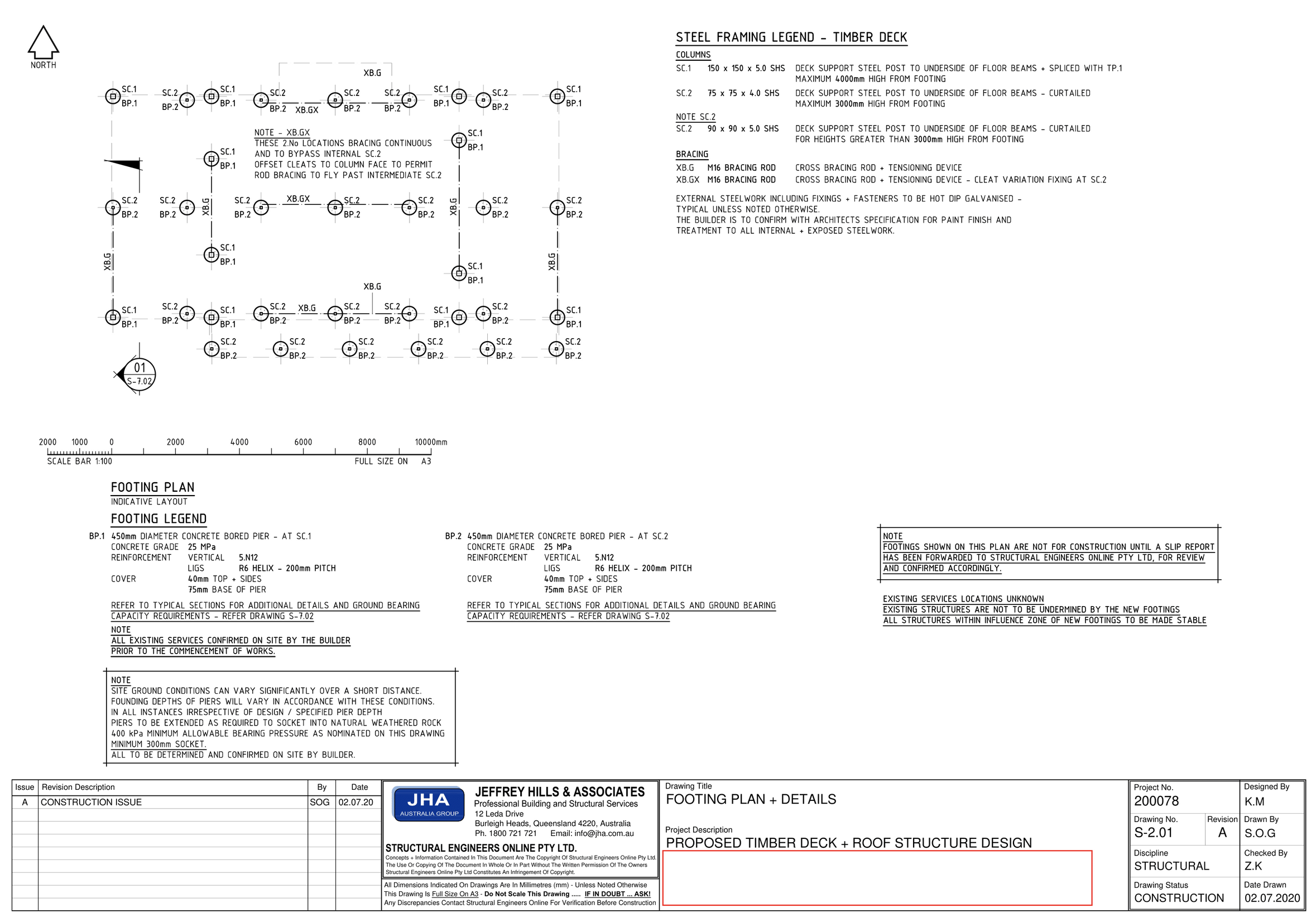
The full plan can be accessed here.
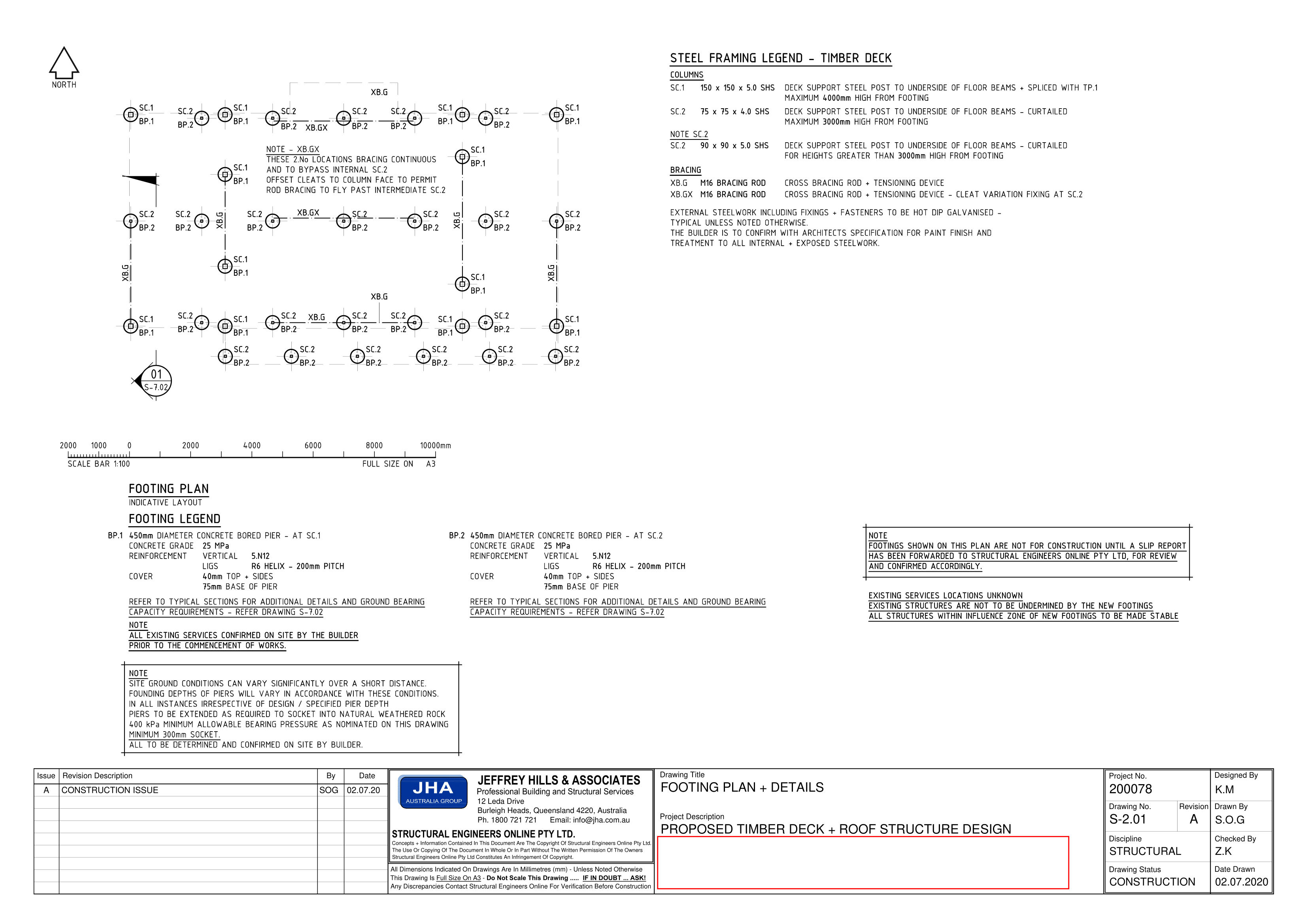
To identify the concrete footing position, you need to refer to the footing plan. The footing plan shows the layout of the footings within the property and the exact location of a specific footing. Based on the plan shown , you can identify the position of concrete footings by referring to the labels ‘BP.1’ and ‘BP.2’ (‘BP’ is an abbreviation for Bored Pier, which is a type of footing). In other words, these labels indicate the name of the footing to be constructed in that position.
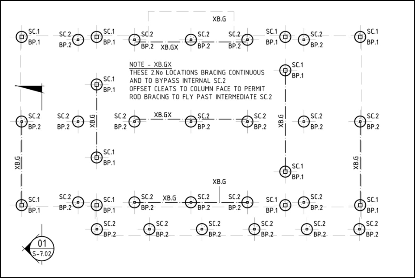
This image shows an enlarged view of the footing plan, which shows the layout and position of the footings.
To identify the sizes of the concrete footing and the type of reinforcing, you must refer to the schedule of footing or the footing legend. Using the same plan, you can see the footing legend on the left side of the sheet.
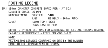
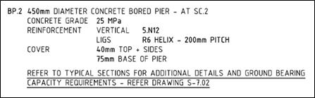
Based on the footing legend, you can tell the size and the type of reinforcing employed for a particular footing. Take concrete footings ‘BP.1’ for example. These footings have a 450 mm diameter. Also, the reinforcement for this type of footing is designated as ‘VERTICAL 5.N12’ and ‘LIGS R6 Helix – 200 mm PITCH’. This means that there are five vertical bars with nominal diameters of 12 mm, and R6 helix ligatures pitched at 200 mm.
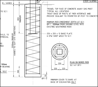
You can refer to the detail drawings to have another perspective of the footing.
Concrete slab
In identifying concrete slab position, sizes, and type of reinforcing, you can use the same methods applied in the previous section. To illustrate this, this plan11 will be used as an example.
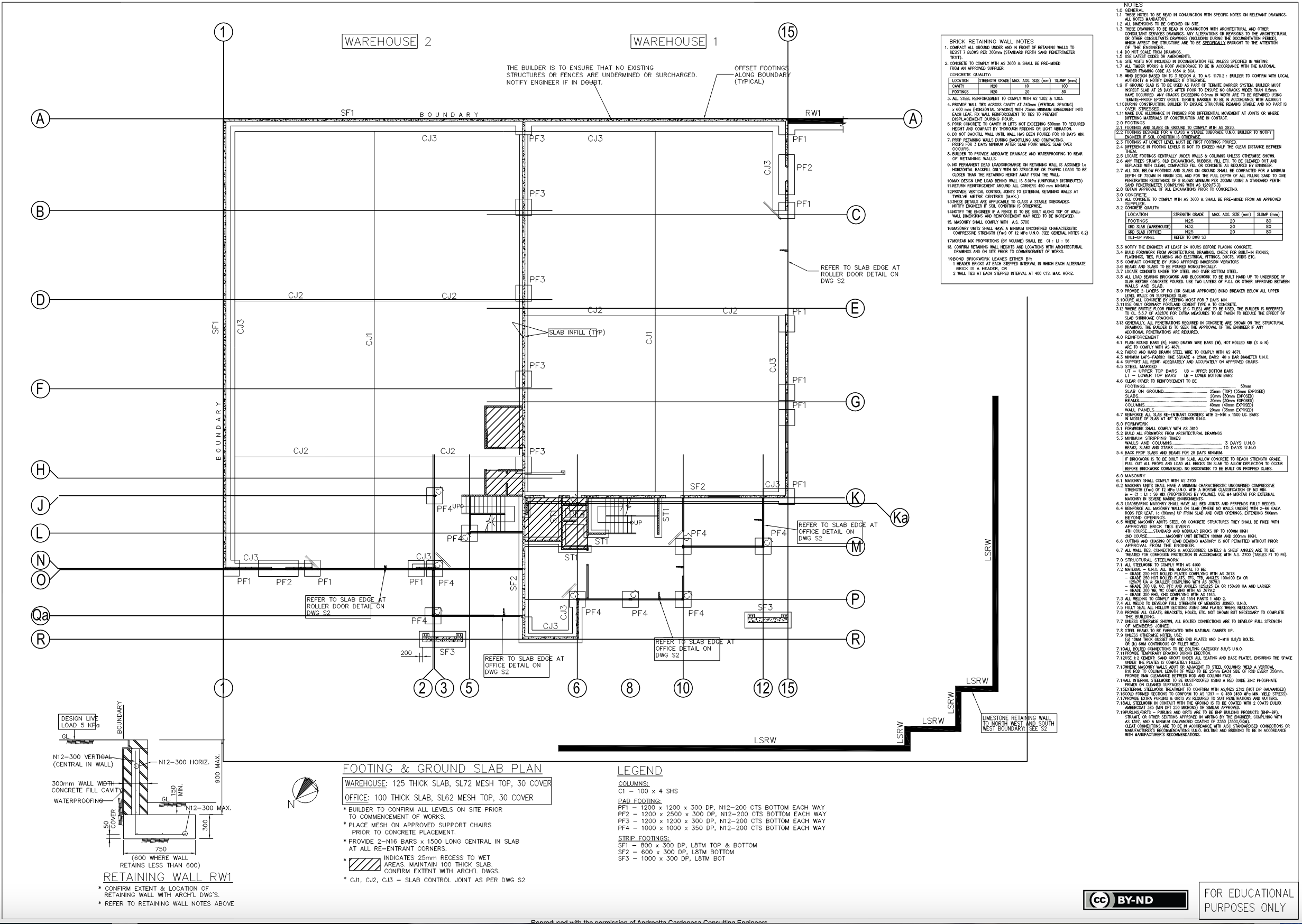
The sheet shows the footing and ground slab plan. In this case, a concrete slab is to be used for ground floor support. Based on the plan, the ground floor concrete slab is positioned in a way that it covers the entire area within the strip footing outline. For some slab edges not bounded by the strip footings, they are labelled accordingly.
In the same sheet, you can also identify the slab sizes and type of reinforcing applied. You can see the details attached at the bottom portion of the sheet.
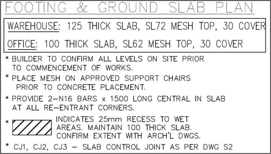
Based on the details, the slab to be used for the warehouse portion must have a size of 125 mm, with the type of reinforcing being an SL72 mesh top reinforcement (seven-millimetre reinforcing bars placed on a grid 200 mm apart). On the other hand, the slab for the office portion must have a size of 100 mm, with an SL62 mesh top reinforcement (six-millimetre reinforcing bars placed on a grid 100 millimetres apart).

Load bearing points refer to points in the building where the transmitted structural loads (e.g. loads from roof, floors, beams) are converted into concentrated loads or point loads and transferred to the foundation soil.
Essentially, the structures responsible for converting the different loads into point loads are the building posts or columns. Thus, in identifying the load bearing points of the building, you need to identify the locations of these columns.
To illustrate this, the plan discussed in the previous section will be used as an example.
Under ‘Legend’ found at the bottom portion of the sheet, you can see the heading ‘Columns:’ and the details of the columns underneath it. For this building project, there is only one type of column named ‘C1’. With that information, you can locate the load bearing points in the plan by finding the label ‘C1’ corresponding to a column.
On the enlarged image shown, the load bearing points are circled in red.
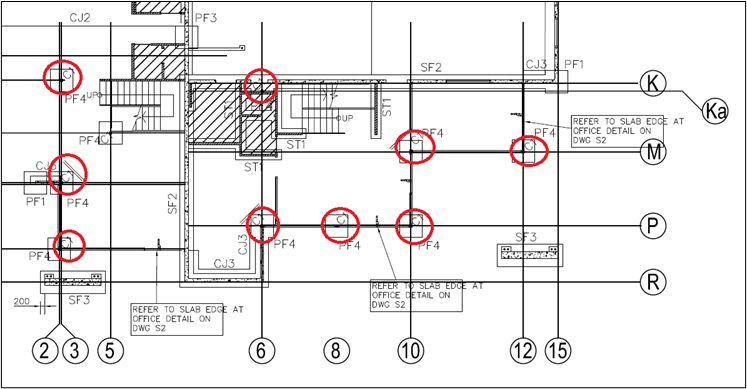
Based on the image above, you can see that the load bearing points are found at the intersection of horizontal and vertical lines with corresponding numbers and letters inside a circle. These are referred to as column grid call out and can be used to locate columns.
Aside from identifying the load bearing points of the building, another important step is to identify structural load bearing information from the plans and compare the information from the specifications. This is to ensure that the details in the plans are consistent with the specifications.
Apart from details pertaining to columns, you can find other structural load bearing details in the plans and specifications such as load bearing brickwork and blockwork, steelworks, retaining walls, and others. Often, load bearing information from the plans can be found on either side of the sheet, although they could also be found in detail drawings.
For example, using the same plan shown, a section at the right side contains the load bearing information of the concrete quality for footings, warehouse ground slab, and office ground slab (see enlarged image).
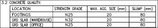
Check that the information stated is consistent with the details in the specifications document. To do this, refer to the specifications document of the building project. Refer to the table of contents and locate the section which covers concrete quality. Review that section and carefully read the specifications stated. You can then check whether the values for strength grade, maximum aggregate size (mm) and slump (mm) have exactly the same values. In cases wherein any mismatch or discrepancy between the plans and specifications exists, you must note these mismatches or discrepancies for a consultation with the relevant construction personnel.
Wind bracing is a structural component employed in a building to provide added structural stability and rigidity against severe wind loads. It uses a triangulation system designed to resist compression and tensional stresses. It can be attached to roofs, as well as to walls, to prevent racking or side-to-side movements.
On the other hand, tie-downs play a significant role in keeping the main structural members, such as wind bracing, from being pulled apart or disassembled. Tie-downs are anchorage mechanisms employed to resist the uplift induced by lateral forces such as wind. This involves the use of bolts, straps, screws, nails, steel plates and others.
The following plan12 will is used to illustrate the identification of wind bracing and tie-down requirements.
The full plan can be accessed here.
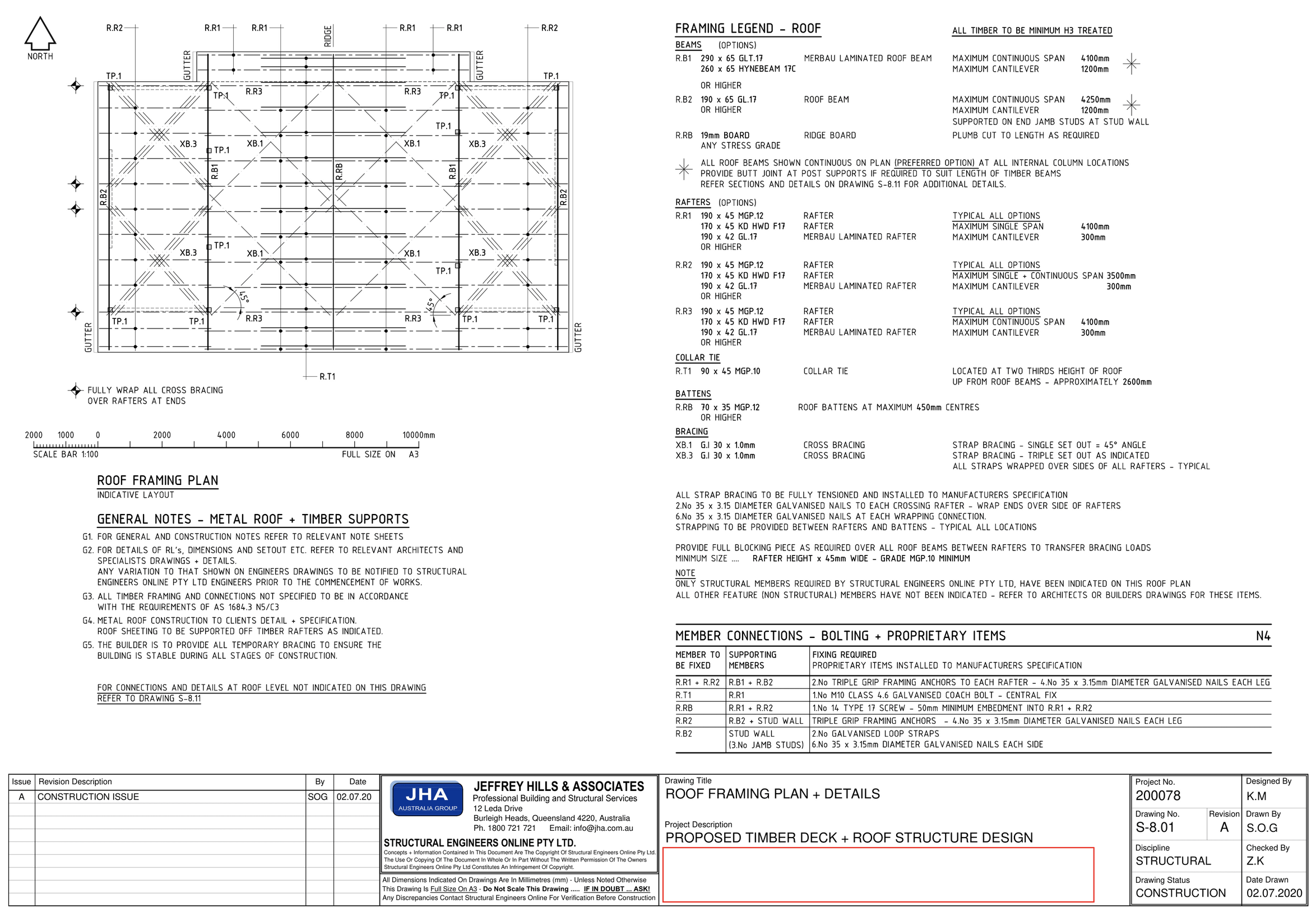
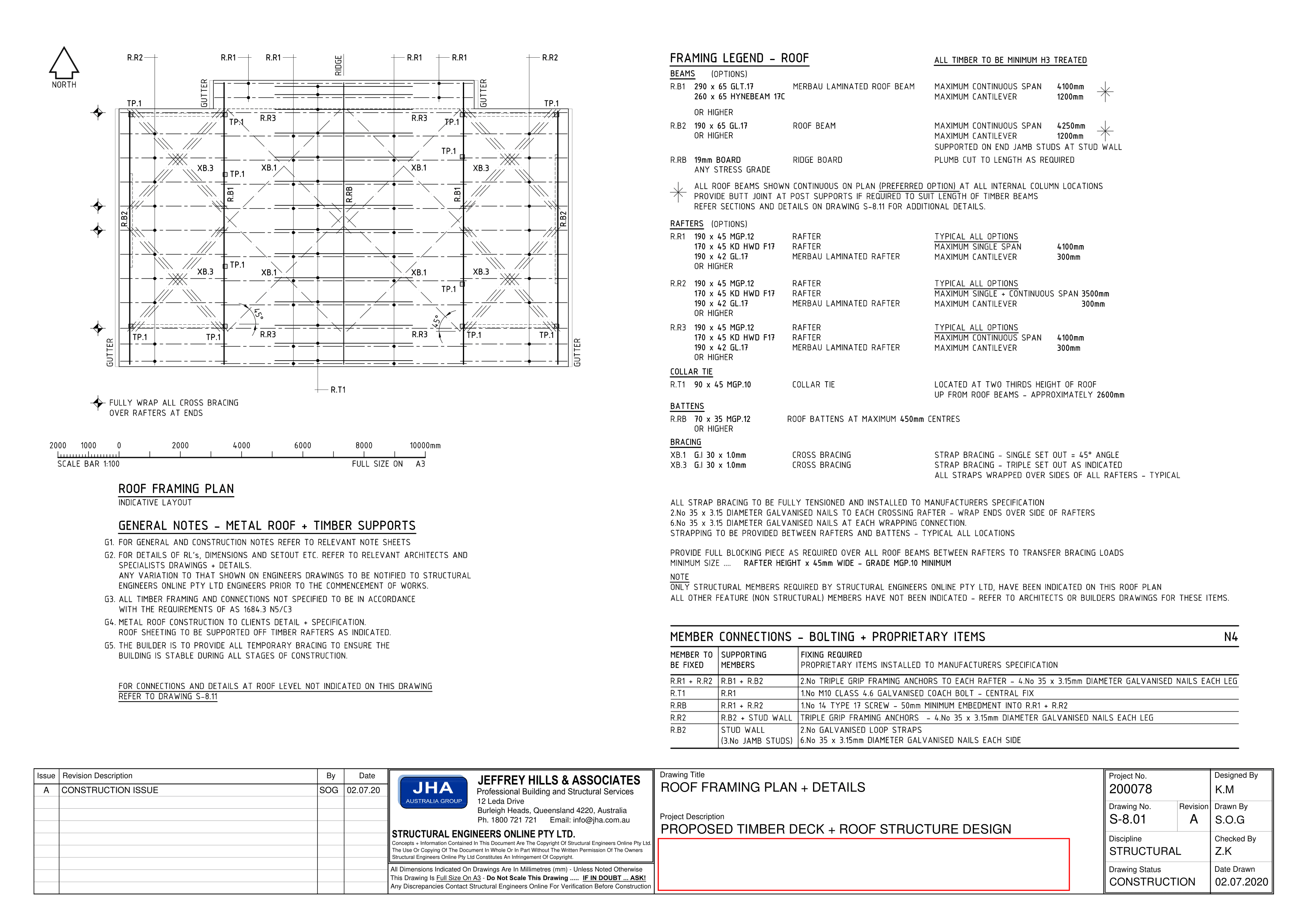
The plan contains the roof framing plan and roof details. The requirements for wind bracing can be found on the right half of the sheet.

Based on the requirements, the cross bracings are to be strap bracings. For bracings labelled as ‘XB.1’ in the roof plan, these bracings are single setouts at 45 degrees and must be 30 x 1.0 mm in size. On the other hand, bracings labelled as ‘XB.3’ in the roof plan are triple setouts with a size of 30 x 1.0 mm. They must be installed in the way they are laid out in the roof plan.
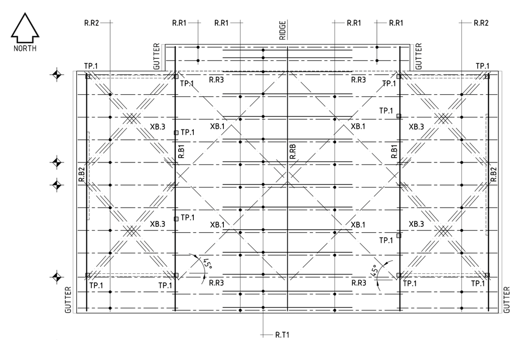
Using the same sheet, you can see the tie-down requirements underneath the bracing requirements.

The requirements stated in the image above tell you the bracing tie-down requirements, which are, in this case, galvanised nails. Furthermore, it provides specifications of the location, quantity, and methods of installation of these tie-downs.
Take note that wind bracing and tie-down requirements are found in the roof plan and the detail drawings. Detail drawings provide large-scale views of wind bracings and tie-downs, which means that you will be able to look further into the configuration of the wind bracings and pick out some of the components required.
You must then check these wind bracing and tie-down requirements from the plans against the wind bracing table. This is to ensure that the details in the plans are accurate and to pick out any discrepancies between the details in the plans and the wind bracing table.
To illustrate how to check wind bracing materials and tie-down methods for accuracy against the wind bracing table, AS 1684.2-2021 Residential timber-framed construction, Part 2: Non-cyclonic areas13 will be used as the reference. A copy of this standard can be purchased from Standards Australia. Alternatively, it can be found at the Additional Resources, at the end of the module.
As mentioned, wind bracings can be applied not only on roofs but also on walls. Say, for example, the plans of the building specify that the wind bracing to be used for walls are two-diagonally opposed timber or metal angle braces. You can check for accuracy against the wind bracing table by referencing Table 8.18 section (a) of the referenced standard. Refer to the image below for the wind bracing table.
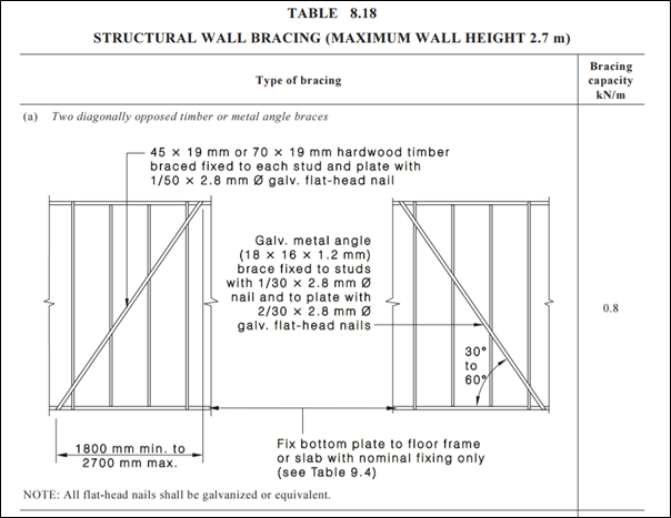
As you can see from table 8.18 in the standard, it shows a drawing of the described wind bracing applied in the plan. The symbol ∅ is used as a shorthand for diameter. You can see information, such as the following:
- Material to be used (e.g. galvanised metal angle brace)
- Size of the brace (e.g. 18 x 16 x 1.2 mm)
- How to install the brace using the required tie-downs (e.g. ‘…brace fixed to studs and plates’)
- Tie-down components (e.g. 1/30 x 2.8 mm ∅ nail, 2/30 x 2.8 mm ∅ galvanised flat-head nails)
After which, you can review and examine the wind bracing and tie-down drawings and details from the plans. During the review, you must check whether the details from Table 8.18 are reflected in the plans. In cases wherein any mismatch or discrepancy between the plans and the referenced wind bracing table exists, you must note these mismatches and discrepancies for a consultation with the relevant construction personnel.