
The National Construction Code
part from the Australian Standards, builders and contractors must also be highly knowledgeable of the National Construction Code (NCC). The NCC is the primary code that provides technical guidelines for designing and constructing buildings and other structures in Australia. It is produced and maintained by the Australian Building Codes Board (ABCB) on behalf of the Australian Government and each State Territory government. The most recent version of the NCC, the NCC 2019, can be freely accessed by logging on to the ABCB site.
HARRYS COMMENT: GRAPHIC TEAM, CAN WE PLEASE RECREATE THIS IN A PRETTIER VERSION?
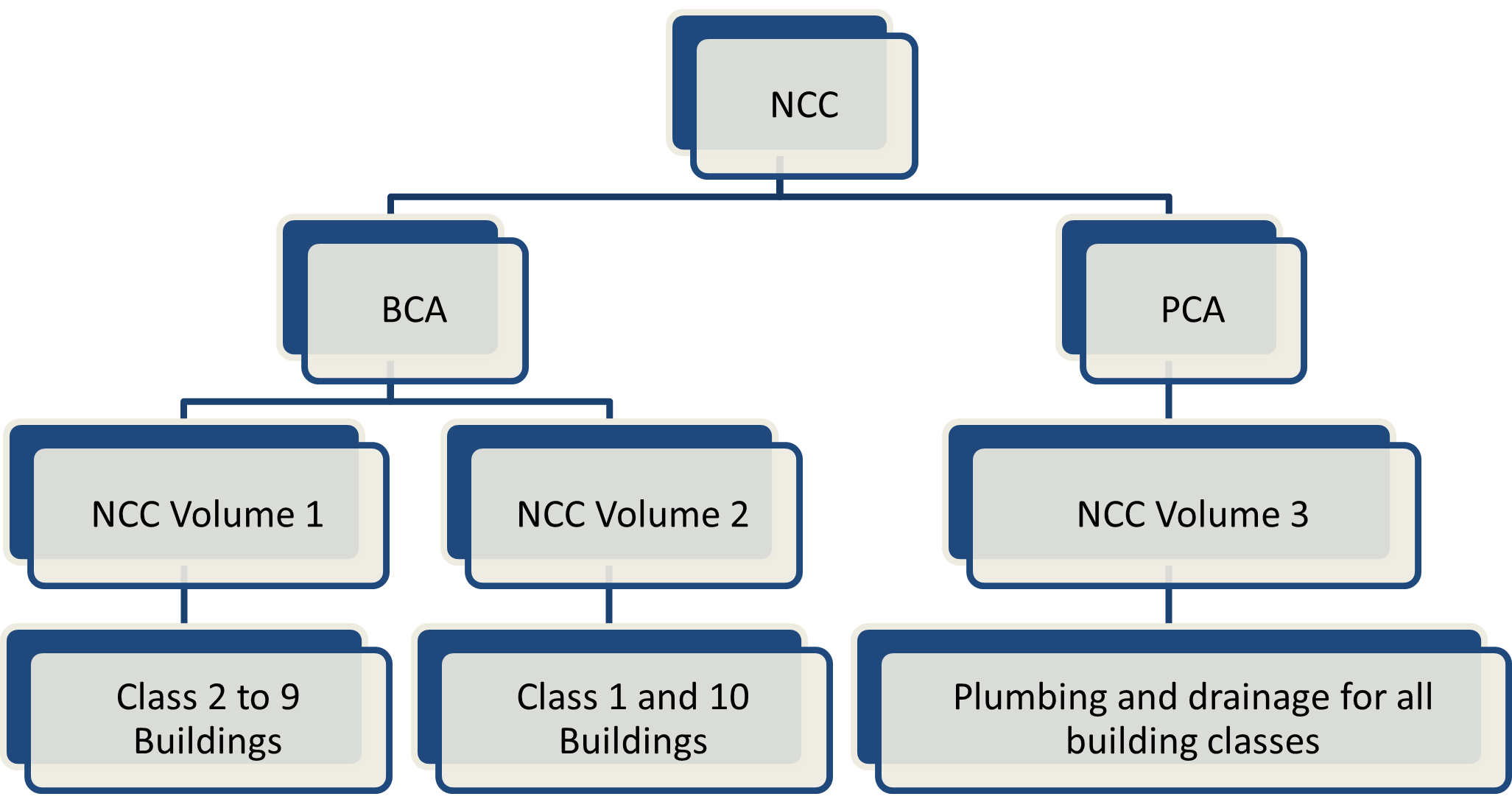
The tables below provide an overview of the content of each volume of the NCC 2019.
Volume 1
NCC Volume 1 covers the requirements applicable for Class 2 to 9 (multi-residential, commercial, industrial, and public) buildings and structures. Refer to the table below for the summary of Volume 1
|
Section Title |
Topics Covered |
||||
|
Governing Requirements |
|
||||
|
B |
Structure |
Structural provisions (design criteria) |
|||
|
|
Performance Requirement |
Verification Method |
|||
|
|
Structural reliability and resistance, glass installations at risk of human impact, buildings in flood areas |
Structural reliability and structural robustness, Deemed-to-Satisfy Provisions, resistance to actions, determination of individual actions, determination of structural resistance of materials and forms of construction, structural software, construction of buildings in flood hazard areas |
|||
|
C |
Fire Resistance |
|
|||
|
D |
Access & Egress |
|
|||
|
E |
Services & Equipment |
warning systems |
|||
|
F |
Health and Amenity |
|
|||
|
G |
Ancillary Provisions |
|
|||
|
H |
Special Use Buildings |
|
|||
|
I |
Omitted |
Existed in BCA 2013; has been removed in BCA 2019. |
|||
|
J |
Energy Efficiency |
|
|||
Volume 2
NCC Volume 2 covers the requirements applicable for Class 1 (residential) and Class 10 (non-habitable) buildings and structures. Refer to the table below for the summary of Volume 2.
|
Section No. |
Section Title |
Topics Covered |
|
|
1 |
Governing Requirements |
|
|
|
2 |
Performance Provisions |
Performance requirements and verification methods for the following construction scope for class 1 and 10 buildings |
|
|
2.1 |
Structure |
Structural stability and resistance, buildings in flood areas |
Structural reliability, structural robustness |
|
2.2 |
Damp and Weatherproofing |
Rainwater management, weatherproofing, rising damp, drainage from swimming pools |
Weatherproofing |
|
2.3 |
Fire Safety |
Spread of fire, automatic warning for occupants |
Avoidance of the spread of fire |
|
2.4 |
Health and Amenity |
Wet areas, room heights, personal hygiene and other facilities, lighting, ventilation, sound insulation, condensation and water vapour management |
Room or space height, verification of suitable natural light, verification of suitable indoor quality, sound insulation, verification of condensation management |
|
2.5 |
Safe movement and Access |
Movement to and within a building, fall prevention barriers |
Wire barriers |
|
2.6 |
Energy Efficiency |
Building, services |
Verification using a reference building, verification of building envelope sealing |
|
2.7 |
Ancillary provisions and Additional Construction Requirements |
Swimming pool access, swimming pool recirculation systems, heating appliances, buildings in alpine areas, buildings in bushfire prone areas, private bushfire shelters |
Combustion appliances, buildings in bushfire prone areas |
|
3 |
Acceptable Construction |
Deemed-to-Satisfy Provisions that are considered to be acceptable forms of construction that meet the legislative requirements for complying with the Housing Provisions |
|
|
3.0 |
Structural Provisions |
Structural design criteria (wind design, structural resistance, guidelines for using structural software) |
|
|
3.1 |
Site Preparation |
Site preparation, earthworks, earth retaining structures, drainage, termite risk management |
|
|
3.2 |
Footings and Slabs |
Footings and slabs, preparation, concrete and reinforcing, site classification, footing and slab construction |
|
|
3.3 |
Masonry |
Unreinforced and reinforced masonry, masonry accessories, weatherproofing of masonry, masonry veneer, isolated masonry piers |
|
|
3.4 |
Framing |
Framing, subfloor ventilation, steel framing, timber framing, structural steel members |
|
|
3.5 |
Roof and Wall Cladding |
Roof cladding, gutters, downpipes and wall cladding, sheet roofing, roof tiles and shingles, gutters and downpipes, timber and composite wall cladding, metal wall cladding |
|
|
3.6 |
Glazing |
Glazing for windows and doors |
|
|
3.7 |
Fire Safety |
Fire properties for material and construction, fire separation of external walls, fire protection of separating walls and floors, fire separation of garage top dwellings, smoke alarms and evacuation lighting |
|
|
3.8 |
Health and Amenity |
Wet areas and external waterproofing, room heights, facilities, light, ventilation, sound insulation, condensation management |
|
|
3.9 |
Safe Movement and Access |
Stairway and ramp construction, barriers and handrails |
|
|
3.10 |
Ancillary Provisions and Additional Construction Requirements |
Swimming pools, earthquake areas, flood hazard areas, construction in alpine areas, construction in bushfire prone areas, attachment of decks and balconies to external walls of buildings, boilers, pressure vessels, heating appliances, fire places, chimneys, and flues |
|
|
3.11 |
Structural Design Manuals |
The content of Part 3.11, which existed in BCA 2016, has been consolidated into a new Part 3.0. The number Part 3.11 has been retained so as not to change the numbering of the current BCA from that of BCA 2016. |
|
|
3.12 |
Energy Efficiency |
Building fabric, external glazing; building sealing, air movement, services |
|
Volume 3
NCC Volume 3 covers plumbing and drainage requirements for all building classes. The table below shows a summary of Volume 3.
|
Section Title |
Topics Covered |
|
|
A |
Governing Requirements |
|
|
B |
Water Services |
|
|
C |
Sanitary Plumbing and Drainage Systems |
|
|
D |
Excessive Noise |
Requirements to prevent excessive noise being generated from a plumbing and drainage system that could cause illness or loss of amenity to occupants in a building |
|
E |
Facilities |
Requirements to allow people with disability to use the facilities provided by a plumbing and drainage system |
Note that you can find references to relevant state-specific legislation and policies at the end of each volume. These policies refer to additional state requirements or variations of the general provisions of the NCC 2019.
Building Classification
The NCC classifies buildings according to the characteristics and intended use of the building and has organised the BCA (NCC Volumes 1 and 2) according to this classification. Therefore, it is critical for all NCC users, particularly builders and contractors, to be familiar with the NCC building classification to identify the requirements appropriate for every project.
The figure below derived from Queensland Building and Construction Commission[4] (QBCC) website provides a summary of the NCC building classifications:
HARRYS COMMENT: CAN WE RECREATE THIS OR JUST USE IT? Fact Sheet: What type of building is it?, used under CC BY 3.0 AU, © The Queensland Building and Construction Commission 2013
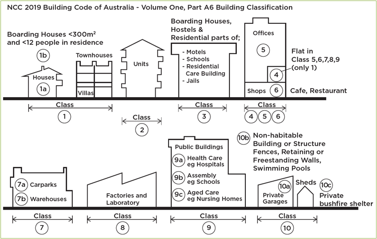
The table below provides further details regarding the NCC classification of buildings.
|
Classes of Building |
||
|
Class 1 |
Class 1 buildings are dwellings. |
|
|
Class 1a |
One or more buildings forming a single dwelling like:
|
|
|
Class 1b |
One or more buildings which together form:
A Class 1b building cannot be located above or below another dwelling or another building class (except for a private garage). |
|
|
Class 2 |
A building containing two or more sole-occupancy units, each being a separate dwelling. |
|
|
Class 3 |
Class 3 buildings are residential buildings other than Class 1 or 2. These are long-term or transient living accommodations for unrelated people. These include the following:
|
|
|
Class 4 |
A Class 4 building is the only dwelling or residence within any Class 5, 6, 7, 8 or 9 buildings. |
|
|
Class 5 |
An office building used for professional or commercial purposes, except for buildings of Class 6, 7, 8 or 9. Examples include:
|
|
|
Class 6 |
Buildings that directly sell goods by retail or supply services to the public, such as:
|
|
|
Class 7 |
Class 7a |
A building which is a car park. |
|
Class 7b |
The following buildings are classified under Class 7b:
|
|
|
Class 8 |
These are process-type buildings such as:
|
|
|
Class 9 |
A building of a public nature. |
|
|
Class 9a |
Healthcare buildings in which occupants are either:
|
|
|
Class 9b |
Assembly buildings used for social, theatrical, political, religious or civil purposes. The following are examples of Class 9b buildings:
|
|
|
Class 9c |
An aged care building. An aged care building is defined as a residential accommodation for elderly people who are:
|
|
|
Class 10 |
A non-habitable building or structure. |
|
|
Class 10a |
A private garage, carport, shed or the like. |
|
|
Class 10b |
Structures like:
|
|
|
Class 10c |
A private bushfire shelter. |
|
Multiple Classifications

Multiple classifications apply when a building serves more than one function. A perfect example is mixed-use buildings, wherein the ground level may be a carpark (Class 7a), and the upper storeys may consist of shops (Class 6) and apartments (Class 2). The different parts of the building must comply with the requirements that apply to their corresponding classifications.
United Buildings
United buildings refer to two or more separate but adjacent buildings connected to form a single building. The connection can be made by creating openings in the walls dividing them. At all times, united buildings must achieve compliance with NCC requirements for a single building.
In cases where united buildings cease to be connected, each building now separated must comply with the NCC requirements for a single building (applicable only for Class 2 to 9 buildings).
Type of Construction Required
The NCC also categorises the types of construction based on the required fire resistance. In general, construction types are grouped into three: Types A, B, and C. The NCC classifies Type A construction as the most fire-resistant type of construction, Type C construction as the least fire-resistant and Type B as the type in between these two.
The requirements for construction are based on the building class and the number of storeys. This is summarised in Table C1.1 of the NCC Volume 1, as shown below:
|
Rise in Storeys |
Class 2, 3, 9 |
Class 5, 6, 7, 8 |
|
4 or more |
A |
A |
|
3 |
A |
B |
|
2 |
B |
C |
|
1 |
C |
C |
Intended use of the building
When different qualities of a building overlap with one another, the building becomes difficult to classify. Thus, the intended use of the building is an important consideration when dealing with Difficult Classifications. Part A6.11 of the NCC Volume 2 provides a discussion regarding Difficult Classifications.
An excerpt of the discussion regarding the intended use of the building is shown below. It details classifying Class 2 and 3 Buildings, as well as classifying Class 6 and 7 Buildings.
HARRYS COMMENT: QUOTE BLOCK
Class 2 or Class 3?
There is a fine line between a Class 2 building containing apartments or flats and a Class 3 motel building with units containing bathroom, laundry and cooking facilities, which may both be made available for short term holiday rental. When does a Class 3 motel unit become a Class 2 holiday flat and vice versa?
In general, an assessment will be based on the most likely use of the building by appropriate authorities.
Class 3 buildings, where the occupants are generally unfamiliar with the building and have minimum control over the safety of the building, represent a higher risk level and therefore require higher safety levels. In a case where the classification is unclear, a decision should be made according to the perceived risks inherent in the use of the building.
Class 6 or Class 7?
Class 7 buildings include those used to sell goods on the wholesale market, whereas Class 6 buildings are used to sell goods to the public.
Some establishments claim to sell goods to both the wholesale and retail markets. As a rule, however, if the general public has access to the building, it is considered a ‘shop’, and therefore a Class 6 building.
Climate zones
The NCC divides the climate of Australia into eight climate zones. The colour coding of the Climate Zone Map shows areas with approximately the same climate. This map is instructional, especially in determining the appropriate thermal requirements for a specific climatic condition. The Climate Zone Map is shown here.

The following provides a brief description of each NCC climate zone:
|
Colour |
Climate zone |
Description |
|
|
Climate zone 1 |
High humidity summer, warm winter |
|
|
Climate zone 2 |
Warm humid summer, mild winter |
|
|
Climate zone 3 |
Hot dry summer, warm winter |
|
|
Climate zone 4 |
Hot dry summer, cool winter |
|
|
Climate zone 5 |
Warm temperate |
|
|
Climate zone 6 |
Mild temperate |
|
|
Climate zone 7 |
Cool temperate |
|
|
Climate zone 8 |
Alpine |


When planning a construction, it is important to consider the climate zone to employ appropriate thermal design. This ensures that energy-efficient heating and cooling systems are in place to provide thermal comfort for the building occupants.
In addition to thermal comfort and efficient use of energy, one importance of determining which climate zone a building project belongs is to anticipate structural loads brought about by climate. These structural loads include, but are not limited to, wind and rain, snow, and thermal loads due to extreme humidity or low temperatures. All these factors need to be accounted for in the structural design to promote the structural integrity of structural components, thus, avoiding structural defects and damages.
Any construction project needs to be analysed for compliance with the NCC requirements for environmental factors such as bushfire, high wind, earthquake and building in alpine regions.
Bushfire

Bushfires are fires that occur in forests, grasslands, and woodlands. Generally, they are slow-moving and could last for days. Brought about due to Australia’s hot and dry climate, bushfires have caused the loss of life and significant property damage. For most of southern Australia, the danger period is summer and autumn, while it occurs in spring and early summer for New South Wales and southern Queensland. In the Northern Territory, these bushfires occur in winter and spring.
Due to the damaging effects of bushfires, measures to control and reduce their impact are implemented in buildings, especially those in more vulnerable areas.
To analyze compliance with the NCC bushfire requirements, one must identify whether the land upon which the building is to be erected is considered a designated bushfire-prone area. According to the NCC,
Designated bushfire area refers to land designated under a power of legislation as being subject, or likely to be subject, to bushfires.
To further discuss this, the state of Victoria will be used as an example.
Mapping of Bushfire Prone Areas in Victoria
Since November 2011, the Minister for Planning for Victoria, under section 192A of the Building Act 1993, has implemented the Designated Bushfire Prone Area (BPA) Map. This map is regularly updated and refined.
Areas are assessed and classified into three Bushfire Hazard Levels. A description of the area, Bushfire Hazard Level, and planning and building response are shown in the table below.
|
Description of Area |
Bushfire Hazard Level |
Response |
|
Areas of extreme fuel loads where there is potential for extreme bushfire behaviour such as crown fire and extreme ember |
Bushfire Hazard Level 2 |
Planning Response: Bushfire Management Overlay (BMO) Building Response: Bushfire Prone Area (BPA), the Building Regulations, and AS 3959:2018 Construction of Buildings in Bushfire-Prone Areas |
|
Areas of high to extreme fuel loads where there is potential for high bushfire behaviour such as a crown fire and ember attack |
Bushfire Hazard Level 1 |
Building response: Bushfire Prone Area (BPA), the Building Regulations, and AS 3959:2018 Construction of Buildings in Bushfire-Prone Areas |
|
Areas where the extent, configuration and/or management of vegetation means that there is low potential for bushfire spread |
Bushfire Hazard Level Low |
Planning Response: No planning response Building Response: No building response outside the Bushfire-Prone Area |
Additionally, new buildings to be constructed in bushfire prone areas must comply with the Bushfire Attack Level (BAL)[11] requirements stated in AS 3959:2018 Construction of Buildings in Bushfire-Prone Areas. A Bushfire Attack Level is a measure of the severity of potential exposure to ember attack, radiant heat and direct flame contact. AS 3959 divides it into six levels which are:
|
BAL rating |
Description |
|
BAL Low |
No significant risk which demands specific construction requirements. However, it is required to build to a minimum BAL of 12.5. |
|
BAL 12.5 |
Ember risk sufficient enough to warrant construction requirements |
|
BAL 19 |
Increased risk due to increased levels of radiant heat and ember attack. This demands construction requirements to prevent damage and spread of fire. |
|
BAL 29 |
Serious risk of the building catching fire due to burning debris and increased heat flux. This demands construction requirements for protection against ember and radiant heat. |
|
BAL 40 |
Has the same risks as BAL 29, but the risk of exposure to flames is significantly higher. This demands construction requirements which enforce the use of materials which possess high resistance to flames. |
|
BAL FZ (Flame Zone) |
Risk of direct exposure to flames. This demands high protection such as heat barriers and modifications to the building and surrounding property. |
Compliance with NCC Bushfire Environment Requirements
To analyse the project for compliance with NCC bushfire environment requirements, you can refer to the provisions set in Part 2.7 and Part 3.10.5 of the NCC Volume 2 and Part G5 of NCC Volume 1.
Two documents are referenced for the compliance of NCC bushfire requirements. These are: AS 3959 and NASH Standard – Steel framed construction in Bushfire Areas.
The Australian Standards AS 3959 provides a discussion regarding bushfire safety requirements of building in a bushfire prone area, as well as the methodology for determining the Bushfire Attack Level (BAL). On the other hand, NASH Standard – Steel framed construction in Bushfire Areas covers economical and robust solutions for non-combustible construction of steel framing in bushfire areas.
The table below shows a summary of the requirements.
|
Document |
Part/Section |
Description |
|
NCC Volume 1 |
GP5.1 |
Performance requirements for Bushfire Resistance |
|
GV5 |
Verification methods for buildings in bushfire prone areas |
|
|
G5.0 |
Deemed-to-Satisfy Provisions for construction in bushfire-prone areas |
|
|
G5.1 |
Application |
|
|
G5.2 |
Protection (compliance with AS 3959) |
|
|
NCC Volume 2 |
P2.7.5 |
Performance requirements for buildings in bushfire prone areas |
|
P2.7.6 |
Performance requirements for private bushfire shelters |
|
|
V2.7.2 |
Verification methods for buildings in bushfire prone areas |
|
|
3.10.5 |
Construction in bushfire prone areas
|
As shown in the table, the NCC Volume 2 states the Performance requirements for private bushfire shelters. The NCC defines private bushfire shelters (Class 10c) as follows:
Private bushfire shelter means a structure associated with, but not attached to, or part of a Class 1a dwelling that may, as a last resort, provide shelter for occupants from immediate life-threatening effects of a bushfire.
High wind

Areas considered to be in a high wind environment are exposed to high-wind conditions that occur during severe thunderstorms, cyclones in tropical areas, and extensive deep low-pressure systems and tornadoes. A map indicating wind regions of Australia is shown here.[13]
The map showing the wind regions of Australia can be used to determine the building requirements for compliance with the NCC high wind requirement. Additionally, it is used by structural engineers to determine the design wind speed appropriate to the region to ensure the stability of building against wind forces.
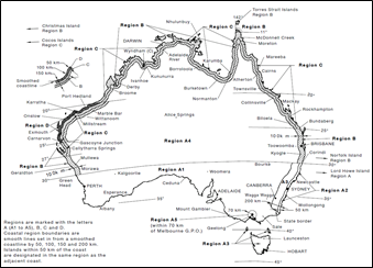
In a structural design perspective, a high wind area refers to ‘a region that is subject to design wind speed more than N3 or C1 (see Table 3)’ (Australian Building Codes Board, 2019, p. 502).[14]
Below is Table 3 of the NCC Volume 2 – wind classes.
|
Non-cyclonic Region A and B |
Cyclonic Region C and D |
|
N1, N2, N3 |
C1 |
|
N4, N5, N6 (these wind classes are covered by Volume Two Part 3.0, Structural Provisions) |
C2, C3, C4 (these wind classes are covered by Volume Two Part 3.0, Structural Provisions) |
Notes:
- A wind classification map identifying wind regions is contained in Volume Two Part 3.0 (see Figure 3.0.1).
- Information on wind classes for particular areas may be available from the appropriate authority.
- “N” = non-cyclonic winds and “C” = cyclonic winds.
Furthermore, NCC defines design wind speed as ‘the design gust wind speed for the area where the building is located, calculated in accordance with AS/NZS 1170.2 or AS 4055 (see Table 3 shown earlier for wind classes).
In the analysis of compliance with NCC high wind environment requirements, one must make sure that the building satisfies the corresponding performance requirements.
The table below shows the relevant section and a short description of the NCC requirements.
|
Part/Section |
Description |
|
|
NCC Volume 1 |
BP1.1(b)(iii) |
Performance requirements for structural reliability against wind action |
|
BP1.4(a) |
Performance requirements for buildings in flood areas (resistance against wind during defined flood event) |
|
|
BV1(b) |
Verification Methods for structural reliability against wind actions |
|
|
B1.2(c)(ii) |
Deemed-to-satisfy provisions for determination of wind actions (compliance with AS/NZS 1170.2) |
|
|
NCC Volume 1 |
B1.2(c)(iv) |
Deemed-to-satisfy provisions for determination of wind actions (compliance with Specification B1.2 for metal roof cladding, its connections and immediate supporting members in cyclonic areas) |
|
B1.2(c)(v) |
Deemed-to-satisfy provisions for determination of wind actions (cyclonic areas) |
|
|
B1.4(l) |
Deemed-to-satisfy provisions for structural resistance of materials and forms of construction |
|
|
Specification B1.2 |
Design of buildings in cyclonic areas |
|
|
NCC Volume 2 |
P2.1.1(b)(iii) |
Performance requirements for structural stability and resistance (against wind action) |
|
3.0.3(c)(ii) |
Structural provisions (acceptable construction practice) for determination of wind actions – compliance with AS/NZS 1170.2 or AS 4055 |
|
|
3.3.5.10(a) |
Acceptable construction practice for masonry wall ties (in relation to design wind speed) |
|
|
3.3.6.1(a) |
Acceptable construction practice (application of part) of isolated masonry pier system in relation to design wind speed. |
|
|
3.4.4.1(a) |
Acceptable construction practice (application of part) of structural steel members in relation to design wind speed |
|
|
3.5.1.0(a) |
Acceptable construction manuals (application of part) of metal sheet roofing |
|
|
3.5.1.1 |
Acceptable construction practice (application of part) of metal sheet roofing |
|
|
3.5.2.1(a) |
Acceptable construction practice (application of part) of roof tiles and shingles in relation to design wind speed |
|
|
NCC Volume 2 |
3.5.2.2 |
Acceptable construction practice regarding fixing of roof tiles and ancillaries in relation to design wind speed |
|
3.5.4.2 |
Acceptable construction practice regarding timber wall cladding in relation to design wind speed |
|
|
3.5.4.3 |
Acceptable construction practice regarding wall cladding boards in relation to design wind speed |
|
|
3.5.4.4 |
Acceptable construction practice regarding sheet wall cladding in relation to design wind speed |
|
|
3.5.4.5 |
Acceptable construction practice regarding eaves and soffit linings in relation to design wind speed |
|
|
3.6.1(a) |
Acceptable construction practice (application of part) regarding glazing in relation to design wind speed |
|
|
3.6.3 |
Acceptable construction practice regarding fully framed glazing installed in perimeter of buildings |
As shown in the tables, two documents are referenced by the NCC: AS 4055 and AS/NZS 1170.2.
AS 4055 Wind loads for housing details methods of assessing the wind classification for one or two storey housing that falls within the geometric limitations specified. This document can be used for Class 1 and Class 10 buildings provided that they meet the dimensional parameters specified.
The standard AS/NZS 1170.2 Structural design actions – Wind Actions states detailed procedures in identifying and calculating wind actions in the design of structures in general. When the building falls outside the geometric limitations set in AS 4055, this document must be used.
Earthquake

Earthquakes are ground vibrations caused by rocks near the fault plane breaking. The impacts of earthquakes include toppled buildings, landslides, liquefaction, tsunamis, and fires caused by downed power lines and ruptured gas mains. Thus, the effects of earthquakes must be considered in the design and construction of buildings.
In the analysis of compliance with earthquake requirements, you must ensure that the building meets the NCC provisions for earthquake actions to ensure building stability and safety. Refer to the table highlighting sections that cover this requirement.
|
Document |
Part/Section |
Description |
|
NCC Volume 1 |
BP1.1(b)(iv) |
Performance requirements for structural reliability against earthquake action |
|
BV1 |
Verification methods for structural reliability |
|
|
B1.2(c)(iii) |
Deemed-to-satisfy provisions regarding the determination of individual actions (structural provisions) |
|
|
NCC Volume 2 |
P2.1.1(b)(iv) |
Performance requirements for structural stability and resistance against earthquake actions |
|
V2.1.1 |
Verification methods for structural reliability |
|
|
3.0.3(c)(iv) |
Acceptable construction practice regarding the determination of individual actions (Structural provisions) |
|
|
3.3.5.1(f) |
Acceptable construction practice (application of part) for masonry veneer |
|
|
NCC Volume 2 |
3.3.5.1(g) |
Acceptable construction practice (application of part) for isolated masonry piers |
|
3.4.4.1(a)(iv) |
Acceptable construction practice (application of part) for structural steel members |
|
|
3.10.2.0 |
Acceptable construction manuals (application part). This is under ancillary provisions and additional construction requirements. |
The document referenced in the NCC regarding earthquake is AS 1170.4 Structural design actions – earthquake actions in Australia. This standard addresses structures subjected to earthquake actions, as well as detailing the requirements to be employed.
Alpine environment
According to the NCC, an Alpine area is:[15]
- likely to be subject to significant snowfalls; and
- in New South Wales, ACT or Victoria more than 1200 m above the Australian Height Datum (AHD); and
- in Tasmania more than 900 m above the AHD
(The Australian Height Datum is a standard vertical reference based on an averaged sea level height).
Additionally, the NCC provides specific locations which are considered to be alpine areas.
In other words, alpine environments are areas found at high elevations and possess mountain or highland climate. These areas are generally cold and snowy. Refer to the image below for the map of the alpine areas in Australia. You can refer to NCC Volume 2 to identify the corresponding locations of the labels shown on the map. 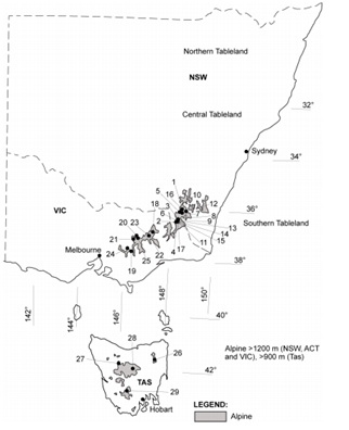
The map is approximate only, and the altitude above the AHD must be used to determine whether the building falls into an alpine area region.
The NCC further states that it is recommended that the appropriate authority be consulted to determine whether the building is located in an alpine area. AS/NZS 1170.3 also contains further detail in identifying alpine areas and the altitude of the alpine regions of Australia.
As mentioned, the NCC references the document AS/NZS 1170.3 Structural design actions – Snow and ice actions. This document provides a discussion regarding structural design values for snow and ice actions
In the analysis of compliance with NCC alpine environment requirements, you must ensure that the building meets the requirements stated in the table below. This table contains the sections and a short description of the relevant NCC alpine environment requirements.
|
Document |
Part/Section |
Description |
|
NCC Volume 1 |
D1.0(iii) |
Deemed-to-satisfy provisions for escape (access and egress) |
|
D2.0(iii) |
Deemed-to-satisfy provisions for the construction of exits (access and egress) |
|
|
D3.0(iii) |
Deemed-to-satisfy provisions for access for people with disability (access and egress) |
|
|
E1.0(iii) |
Deemed-to-satisfy provisions for firefighting equipment |
|
|
E2.0(iii) |
Deemed-to-satisfy provisions for smoke hazard management |
|
|
E4.0(iii) |
Deemed-to-satisfy provisions for visibility in an emergency, exit signs and warning systems |
|
|
NCC Volume 1 |
GP4.1 |
Performance requirements for external doorways (construction in alpine areas) |
|
GP4.2 |
Performance requirements for structures forming pathways in snow conditions (construction in alpine areas) |
|
|
GP4.3 |
Performance requirements for control of falling ice and snow (construction in alpine areas) |
|
|
GP4.4 |
Performance requirements for fire safety systems in alpine areas (construction in alpine areas) |
|
|
G4.0 |
Deemed-to-satisfy provisions for construction in alpine areas |
|
|
G4.1 |
Deemed-to-satisfy provisions (application of part) for construction in alpine areas |
|
|
G4.3 |
Deemed-to-satisfy provisions for external doors |
|
|
G4.4 |
Deemed-to-satisfy provisions for emergency lighting |
|
|
G4.5 |
Deemed-to-satisfy provisions for external trafficable structures |
|
|
G4.8 |
Deemed-to-satisfy provisions for firefighting services and equipment |
|
|
G4.9 |
Deemed-to-satisfy provisions for fire orders |
|
|
NCC Volume 2 |
P2.7.4 |
Performance requirements for Buildings in alpine areas |
|
3.2.1(e)(i) |
Acceptable construction practice (application of part) for footings and slabs (in relation to alpine area) |
|
|
3.3.5.1(e) |
Acceptable construction practice (application of part) for masonry veneer (in relation to alpine area) |
|
|
3.3.6.1(f) |
Acceptable construction practice (application of part) for isolated masonry piers (in relation to alpine area) |
|
|
3.10.4.1 |
Acceptable construction practice (application of part) for construction in alpine areas |
|
|
3.10.4.2 |
Acceptable construction practice for external doors (in alpine areas) |
|
|
3.10.4.3 |
Acceptable construction practice for external trafficable structures (in alpine areas) |
|
|
3.10.4.4 |
Acceptable construction practice for clear spaces around buildings (in alpine areas) |
|
|
3.10.6.1(a) |
Acceptable construction practice (application of part) for attachment of decks and balconies to external walls of buildings |

Building design and structural integrity
Building design refers to the application of architectural, engineering, and technical concepts to the design of structures to comply with client requirements and legal building requirements. This is made possible by industry professionals who hold the necessary knowledge, skills, and licence to perform such technical tasks.
From a structural building design perspective, important industry professionals include structural engineers who design stable and safe structural components and geotechnical engineers who investigate the soil to make sure it can withstand the building's weight. Builders also play an important role in building design since they are responsible for ensuring that project documentation is followed, state regulations and necessary codes are implemented, and work safety is observed at all times.
Structural integrity is the ability of a structure to perform its structural function of resisting loads such as self-weight and other dead loads, live loads, earthquake, and wind loads throughout its intended life span. When a building has structural integrity, it is considered stable and safe from failure, resulting in injuries, damage, and potential loss of life.
Designing for structural integrity needs to consider all possible forces that the building will be subjected to. This includes making correct assumptions regarding the magnitude of these loads and complying with the corresponding design codes and building regulations.
After a structure is built, regular building inspections are required, especially after events such as earthquakes occur. This is to check for any signs of defect, damage, or deterioration of building components and evaluating whether any maintenance procedure must be carried out. If any damage, especially major damage, is observed, repairs must be performed to protect the building's structural integrity.
To analyse the structural integrity, you need to have a deep understanding of important structural principles.
Behaviour of structural materials
Fundamental Types of Loading
Structural members behave in a particular manner in response to different types of forces. Examining fundamental types of loading will explain how these individual structural components react upon resisting and transmitting loads.
HARRYS COMMENT: GRAPHIC TEAM, CAN WE RECREATE THIS GRAPHIC PLEASE?
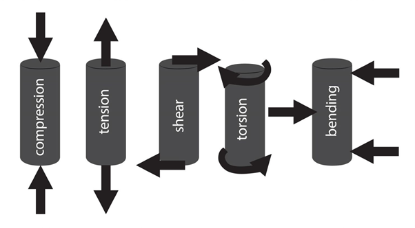
The graphic above shows how fundamental types of loading affect structural components.
- Compression – loading condition that compresses the material together. This loading applies to footing, columns, retaining walls, and truss members.
- Tension – loading condition that, as opposed to compression, stretches or pulls the member apart. This loading applies to truss members and connections.
- Shear – loading condition that causes the member to slide apart along a plane that is parallel to both end forces as shown. This applies to beams, slabs, columns, roof trusses, wind bracings, footing, and retaining walls.
- Torsion – loading condition that causes twisting in a structural component. This applies to beams and slabs.
- Bending – loading condition that causes the member to experience compression on one side and tension on the other. This loading applies to all structural members mentioned excluding roof truss and wind bracings.
Stress, Strain, and Deformation
There are two ways to look at how individual structural components react against the fundamental types of loading. These concepts are called stress and strain. An example to explain both concepts can be through the simple act of stretching a rubber band.
In stretching a rubber band, tensile forces must be applied at opposite ends. As a result, a change in the length or deformation of the rubber band can be observed. The magnitude of the tensile force exerted on the rubber band divided by the cross-sectional area of the rubber band is called stress. The amount the rubber band is stretched, divided by the original length is called strain.
Stress is very apparent when looking at project plans and specifications. The unit kilopascal, expressed in kN/m2 or kPa, is used as a unit measure of stress and is the quantitative description of the magnitude of the strength of construction materials (e.g. steel, concrete). Strain is dimensionless as it is a measure of the change in length, divided by the original length.
Dead, live and wind loads
Loads are key elements that influence the structural integrity of the building. Understanding the concepts of these loads will help you analyse the building's structural integrity to give you an idea of how these loads affect a structure.
Before discussing the three loads (dead, live and wind load), it is important to take note of the two classifications of loads: gravity loads and lateral loads.
Gravity loads are vertical loads applied to the building. Dead load and live load belong in this category. A simple example of this type of load is carrying a suitcase. The weight of the suitcase acts vertically against the force from your arms.
On the other hand, lateral loads are horizontal loads applied perpendicular to the structure. Wind load belongs in this category, together with earthquake load and earth pressure load. A basic example of this is when a roof structure gets detached due to severe wind from thunderstorms.
Three of the important loads to be considered – dead load, live load, and wind load – will be discussed below.
Dead Load
As per AS 1170.0 Structural design actions: General principles, this load is referred to as permanent actions. A dead load is the weight of structural components such as stone, concrete or steel decking and masonry partitions, and architectural finishes like cement flooring and roof tiles.
As formally stated in the NCC, permanent actions include the dead loads of the building or structure. These include the load imposed by the building’s components, including the forces imposed by the floors, walls, roofs, suspended ceilings, etc.
Live Load
As per AS 1170.0 Structural design actions: General principles, this load is referred to as imposed actions. This includes people, furniture, vehicles, and other non-permanent loads. The NCC also specifies imposed actions to include construction activity actions that are defined as actions due to stacking of building materials or equipment, including cranes and trucks, during construction or actions that may be induced by floor-to-floor propping.
As the NCC defines it, imposed actions include live loads on the building or structure. These include the load arising from construction activity and the intended use or function of the building or structure.
Wind Load
This type of force is caused by wind and results in the building experiencing either pressure or suction. The magnitude of wind load increases as the building extends higher and varies depending on the location.
Performance of beams
Beams are horizontal members that primarily carry gravity loads such as their own weight, partitions, and all loads coming from roof trusses or floor slabs. Their design also needs to resist lateral loads induced by earthquake and wind to provide further stability. Beams transmit the loads directly to vertical supports called columns, although in some cases, they may transmit loads to larger beams called girders or to load bearing walls.
An image of a steel beam is shown here.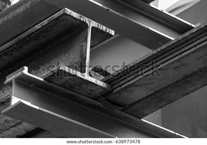
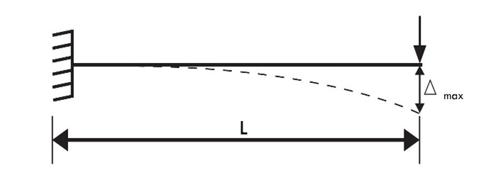
Upon application of loads, the beam exhibits two types of reaction: shear and bending resistance. Shear resistance occurs mainly at the end supports. This prevents the beam from collapse or detachment from the supports. Maximum bending resistance occurs at the centre span for simple supported beams. This bending resistance prevents the beam from failing due to bending forces from imposed gravitational loads. Consequently, the beam tends to undergo deflection, which defines the degree of beam deformation due to the imposition of these gravity loads. In the case of a simple supported beam, the maximum deflection occurs at the centre span of the beam, as shown in the image.
HARRYS COMMENT: GRAPHIC TEAM, CAN WE RECREATE THIS GRAPHIC PLEASE?
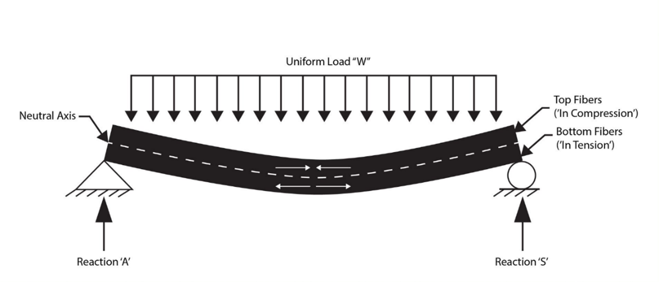
Based on the image, the initial length of the beam is slightly reduced at the top of the beam due to compression, while the length of the beam slightly increases due to tension at the bottom of the beam.
Deflection is an important criterion in the structural design of beams, especially for beams in contact with brittle material such as glass. In this case, excessive deflection has to be avoided to prevent the glass from breaking. Deflections are also controlled to promote aesthetics.
Similar to deflection but happening over a longer time frame is concrete creep. Concrete creep occurs when a constant load is applied to concrete elements such as beams and is the displacement of the concrete due to this constant force. Structural designers consider this factor in the structural design so that beams will perform well under constant loading.
Timber Beams
Due to loads applied, all beams experience deflection, including timber beams. However, another aspect worth noting about the performance of timber beams is their behaviour when exposed to fire. In some cases, it is advantageous to use timber for beams and other structural components since timber burns slowly. This property of timber allows fire safety respondents to predict and measure the behaviour of fire, potentially making it safer than other construction materials.
Type of Material and Profile
Beams may be characterised by the type of materials they are made of and their profile (or shape of cross-section).
These are the following.
Reinforced concrete
Concrete beam embedded with steel reinforcement bars for resistance against tensional force. Conventional reinforced concrete beam shapes include rectangular, T-section, Inverted T-Section, and L-section.
Steel
Shapes include I-shaped, T-shaped, H-shaped, C-shaped, and tubular
Timber
Shapes include square and rectangle
Composite steel & concrete
Individual steel and concrete components held together by a suitable structural connection system to form a single unit. Thus, the resulting shape is a hybrid of the steel shapes and reinforced concrete shapes mentioned previously.
Manner of Support
Additionally, beams may be classified according to the manner of support. Manner of support refers to the support condition or system that defines the transfer of load from the beam to the supporting structure.
HARRYS COMMENT: GRAPHIC TEAM, CAN WE RECREATE THE GRAPHICS BELOW.
The table below shows the manner of support, the corresponding definition, and the location of the maximum deflection when subjected to a uniformly distributed load.
|
Description |
Location of Maximum Deflection |
Illustration |
|
|
Simply Supported |
Beams with end supports that allow rotation (no moment resistance) |
Centre span |
|
|
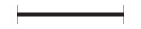
Fixed Support |
Beams with end supports that do not allow rotation (moment resistance) |
Centre span |
|
|
Cantilever |
Beams with fixed support only at one end |
Non-fixed end (free end) |
|
|
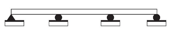
Continuous |
Beams extending over two or more supports |
Centre span |
|
|
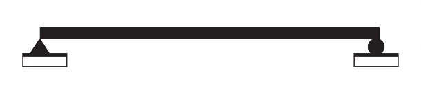
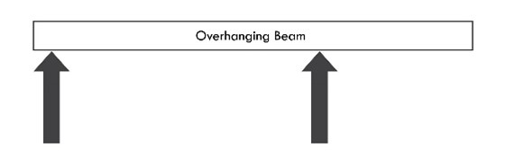
Over Hanging |
Simple beams with a span extending beyond one end support |
Depends on span lengths (either on the simple span or the overhang end) |
|
|
Double Overhanging |
Simple beams with spans extending beyond each end support |
Depends on span lengths (either on the simple span or the overhang end) |
|


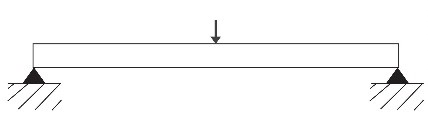
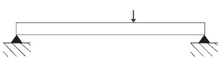
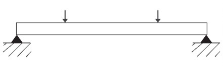
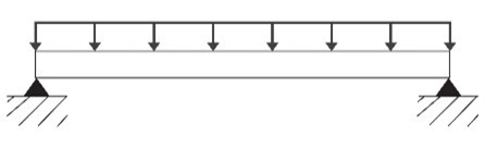
Beam Loading
Beam loading refers to the manner in which a load is imposed on a beam, creating reaction forces at beam supports and inducing internal stresses, strains, and deflections throughout the beam span. The reaction of the beam varies accordingly with the magnitude and loading to which the beam is subjected. The table below shows examples of beam loading.
HARRYS COMMENT: GRAPHIC TEAM, CAN WE RECREATE THE GRAPHICS BELOW.
|
Beam Loading |
|
|
Point load at centre |
|
|
Intermediate point load |
|
|
Two equidistant point loads |
|
|
Uniformly distributed load |
|
Location of Maximum Beam Deflection
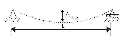
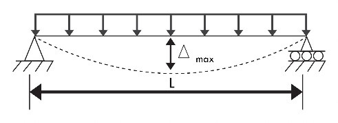
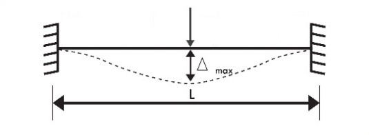
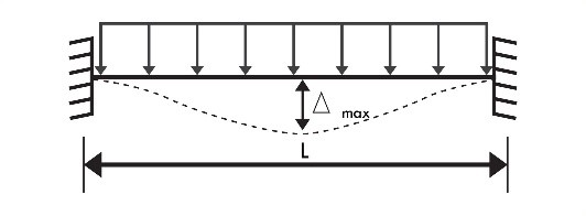
The table below shows the deflection behaviour of beams and the location of the maximum deflection under the given point loading and uniformly distributed loading conditions. The maximum deflection is labelled as ∆max , while the span length of the beam is labelled L.
HARRYS COMMENT: GRAPHIC TEAM, CAN WE RECREATE THE GRAPHICS BELOW.
|
Manner of Support |
Explanation |
|
|
Simply supported |
No deflection occurs at the endpoints since the beam is fully supported at both ends. Since no support exists at the centre, the beam tends to deflect the most at this part. The degree of deflection decreases as the length travels from the centre towards the end support. |
|
|
|
||
|
Fixed Support |
No deflection occurs at the endpoints since the beam is fully restrained at both ends. The beam tends to deflect the most at the midpoint. The degree of deflection decreases as the length travels from the midpoint towards the support. |
|
|
|
||
|
Cantilever |
No deflection occurs at the left endpoint since the beam is fully fixed at this point. The beam tends to deflect the most at the right end, which is the free end. The degree of deflection increases as the length travels from the fixed end support towards the free end.
|
|
|
|
Engineers pay close attention to the deflection of beams, especially in cases where a brittle material such as glass windows are situated under a beam. Excessive beam deflections, especially near installed glass, could lead to progressive cracks or shattering of the glass structure. As construction personnel, you have the responsibility to be aware of such occurrences since these are directly related to the building's structural integrity.
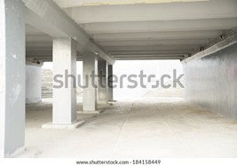
Performance of columns
Columns are vertical components that carry vertical loads transmitted from beams, slabs, or trusses and transfer these loads down to the foundation. In this case, columns are considered compression members. However, like beams, columns are also designed to resist bending stresses induced by lateral loads such as earthquake and wind. Thus, columns are also considered as bending members.
Columns exhibit two general behaviours when subjected to loads: compression and bending. The former occurs when the column is subjected to a concentric load which is defined as a load that passes exactly through the centre of the column cross-section. On the other hand, the latter occurs when the column is subjected to an eccentric load which is defined as a load that does not coincide with the centre of the cross-section. This bending reaction due to eccentric loading condition in compression members is commonly called buckling. An image of concrete columns is shown here.
Construction Material and Shape
Columns can be classified by the type of materials which they are made of and the cross-sectional shape. These are the following.
Reinforced Concrete
Concrete column embedded with steel reinforcement bars for resistance against tensional forces and buckling. Conventional reinforced concrete beam shapes include rectangular, square, and circular. Additionally, L-shape and T-shape columns also exist and are used on the corners of boundary walls.
Reinforced concrete columns can be classified based on how steel reinforcements are laid and arranged before the concrete is cast. This must comply with relevant standards and codes. Tied columns employ reinforcements suitable for rectangular or square column cross-sections, while spiral column reinforcements are required for circular columns.
Steel
Steel column shapes include I-shapes, channel, equal angle, and T-shape. However, shapes could be employed with connection systems such as bolts and welds to form hybrid shapes according to necessity or preference. These are called built-up columns. Relevant standards and codes must be observed when making such columns.
Although steel columns have good compressive strength similar to that of masonry brick columns, they are prone to buckling under heavy compressive loads.
Timber
Timber columns usually employ rectangular column cross-sections.
Masonry Brick
One of the most common construction materials in Australia is brick. Brick columns include shapes such as rectangular and square. They possess high compressive strength, which is advantageous in carrying compressive loads.
Composite steel and concrete
These are shapes that combine steel and concrete to form a single unit that possesses the qualities of each material. One of the common applications of composite steel and concrete is standard steel section encased in concrete to give high strength with a small cross-section and good performance against fire.
Reactive powder concrete columns
This type of column is composed of the same mixture as ordinary concrete except that the aggregates are replaced with components such as quartz powder, silica fume, steel fibres, etc. This gives the column a higher compressive strength compared to ordinary concrete. Additionally, this type of column possesses high ductility like steel but can carry twice the compressive stress that steel columns can resist.
Column Loading
Columns may also be classified according to the loading condition they are subjected to. The loading condition greatly affects how columns behave or react. These are the following.
Axially loaded column
Columns subjected to concentric loads. This means that vertical loads act through the centre of gravity of the cross-section. The column exhibits pure compression in this loading condition. In a practical perspective, axially loaded columns are interior columns in buildings with symmetrical loads from floor slabs from all sides.
Column with uniaxial eccentric ¬loading
Eccentric loads do not coincide with the centre of gravity of the column cross-section but rather act eccentrically on one axis only, either the x-axis or y-axis of the cross-section. In this loading condition, the column exhibits both compression and bending along one axis. In a practical perspective, these loading conditions are encountered in edge or side columns.
Column with biaxial eccentric ¬loading
In this loading condition, the load does not act eccentrically on either the x-axis or y-axis of the cross-section. The column is subjected to both compression and bending. In a practical perspective, these loading conditions are encountered in corner columns.
Performance of roof trusses
A roof truss is a framework that provides roof support. Usually, trusses are set at regular intervals and connected by longitudinal members called purlins. Bay is the term that describes the space between two trusses.
The main function of roof trusses is to resist roof loads such as rain, snow, and wind, as well as roofing elements like shingles and tiles and live loads in accordance with standards. In general, trusses employ a triangulated system and are designed to resist only tension and compression forces. Thus, trusses are considered to be two-force systems. They transfer these loads to beams or columns. Other applications of trusses include bridges and towers.
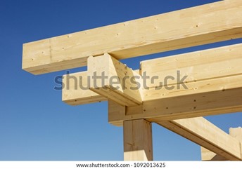
The image below shows a timber roof truss set at regular intervals.
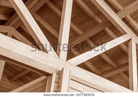
Additionally, trusses require less material to support loads, making them more economical than solid beams.
Different types of trusses exist, and applying a specific type depends on various factors and considerations.
Safety Factor of Timber and Steel Trusses
In general, roof trusses are composed of either timber or metal (i.e. steel). Timber trusses have a high degree of resistance to fire damage (they only burn slowly, giving time for people to respond to it) and exhibit low expansion (increase in length) when exposed to high temperatures. However, they need waterproof and termite treatment to resist damage.
Steel trusses, on the other hand, are resistant to termite damage and are generally durable. However, they have very low resistance against fire and melt when exposed to extremely high temperature. They require the application of fire protection procedures to increase their safety, as well as waterproofing procedures to resist corrosion.
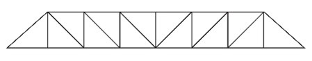
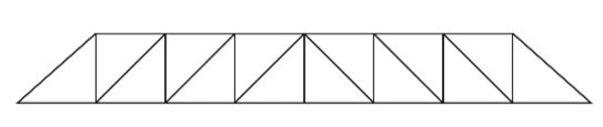
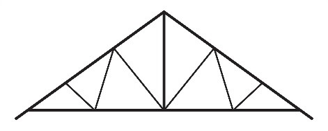
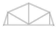
Types of trusses
Below is a table of the different types of trusses.
HARRYS COMMENT: GRAPHIC TEAM, CAN WE RECREATE THE GRAPHICS BELOW.
|
Description |
|||
|
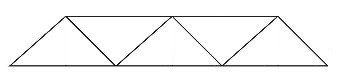
Warren Truss |
Consists of a series of equilateral triangles, alternating up and down |
|
|
|
Pratt Truss |
Considered to be the most efficient under static vertical loading. This consists of vertical and diagonal members for compression and tension, respectively. |
|
|
|
Howe Truss |
A truss whose geometry is the opposite of that of the Pratt truss |
|
|
|
Fink Truss |
Consist of web members that follow a V-pattern which becomes smaller as the top chord slopes downwards |
|
|
|
Gambrel Truss |
Consists of the top chord having two different slopes, wherein the outer slope is relatively steeper than the preceding one. The space in the centre of the truss could be utilised as storage area. |
|
|
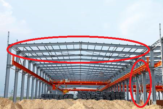
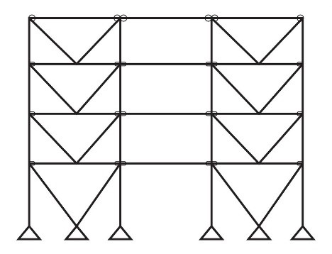
In general, bracing is a structural system employed to provide added structural stability and rigidity against lateral loads such as earthquakes and wind. Wind bracings mainly resist wind loads and may be attached to roofs and walls to prevent racking or side-to-side movements.
Like roof trusses, wind bracings employ a triangulation system and are designed to resist only compression and tension. Thus, wind bracings are considered two-force systems. The image shows a steel warehouse structure employing cross-wind bracing on the roof and walls.
Types of bracing
Refer to the table below for the types of bracing employed in a building.
|
Type |
Description |
Illustration |
|
Single Diagonals |
Consist of employing single diagonal structural members that are sufficient to resist tension and compression. |
|
|
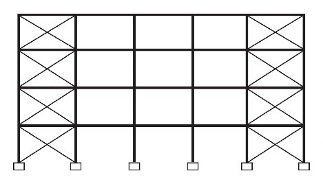
Cross-bracing |
Also called ‘X-Bracing’, this bracing system employs two intersecting diagonal structural members that must be tension resistant. The main downside of this system is that it compromises the positioning of window openings on building façades. |
|
|
K-bracing |
Consist of diagonal members connected to columns at mid-height. Unlike cross-bracing, k-bracing provides openings in the building façade. |
|
|
V-bracing |
Consist of two diagonal members that form a V-shape, connecting the upper two corner points towards the centre point of the lower member. |
|
|
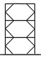
Chevron bracing |
Also known as ‘inverted V-bracing’, is a brace system with opposite geometry to V-bracing. |
|
Solution of force systems
Buildings are subjected to forces from different sources. When these various forces act on a building, they constitute a system of forces. The basic principles of force systems are the following:
- Coplanar Force System – force system wherein all forces lie in the same plane
- Concurrent Force System – force system wherein all forces pass through a single common point
- Collinear Force System – force system where all forces act through a single line
- Parallel Forces System – force system where two or more forces act parallel to each other
In a more realistic sense, these force systems act simultaneously. Some forces may act in a single plane and through a common point, making it a coplanar concurrent force system. Another example would be forces that act parallel to each other but not found in the same plane, making it a non-coplanar parallel force system.
In the planning stage, it is necessary to determine what forces the building will be subjected to provide an effective system that will counteract them. Simply, this is referred to as a solution to force systems. This includes making expert assumptions regarding the direction and magnitude of these forces and necessary structural design calculations to ensure resistance and stability against these forces.
Structural designs and specifications
Structural designs and specifications are part of the larger set of documents called project plans and specifications. Structural designs and specifications contain structural drawings, layouts, requirements, and instructions that must strictly be followed and implemented in the construction phase. The topics discussed previously, such as the behaviour of structural materials, the application of different loads, the performance of beams, columns, roof trusses, wind brace, and solution of force systems, define the elements and specifications found in the document.
As construction personnel, it is your responsibility to correctly identify and interpret details in the structural designs and specifications documents. This is necessary to analyse the building design and structural integrity of a building and check whether the building's structural integrity is maintained.
Before discussing how to analyse the building design and structural integrity from the structural designs and specifications, you must first know what information can be found in the document.
The items listed below consist of the structural designs and specifications document:
- General notes & specifications
- Elevation and section view
- Foundation plan & specifications
- Floor framing plan & specifications
- Roof framing plan
- Connections and steelwork details
General Notes and Specifications
General Notes and Specifications covers all general material and procedural requirements to be implemented on the site. These include design assumptions, geotechnical report details, subgrade preparation, foundation, concrete notes, timber notes, and structural steelwork notes. Attached below are the sheets containing General Notes & Specifications of a timber deck with roof structure for you to see the type of detail provided. Access Sample A-01 and Sample A-02 here.
Elevation and section views
The elevation view shows the building's exterior, including front and rear views and the left and right-side views. The section view shows a cutaway view from an imaginary plane that cuts through the building. The cutting plane allows one to see through the structure's interior, which is otherwise concealed by the exterior walls. Construction personnel can use elevation and section view details to help them visualise the building’s exterior and interior. Additionally, elevation and section view details can be referenced to check whether the elevation of a floor or other structural elements are maintained and installed according to the structural design.
The images below show the elevation and section view of a steel warehouse structure.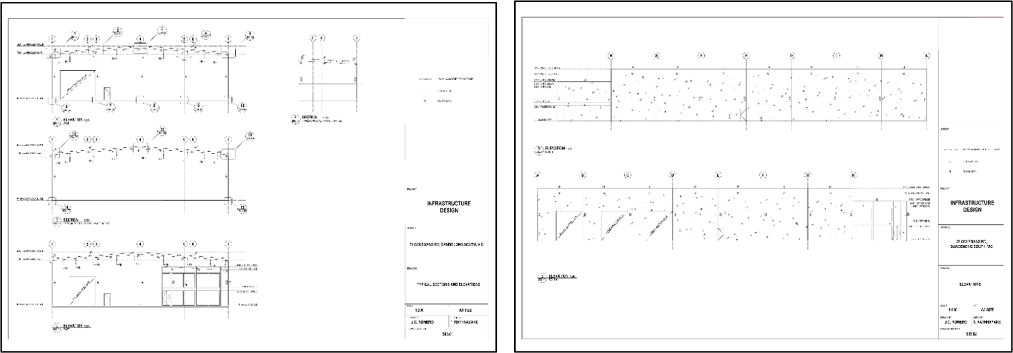
Access warehouse portal frame-02 and warehouse portal frame-03 here.
Foundation plan and specifications
The foundation plan shows the engineer’s footing design and specifications and is especially important during the phases of building set out and laying out of footings. It shows the top view of the footings position relative to the property line and other structural components. Construction personnel can use this section as a reference to determine distances between columns and footing, locate their positions in the construction site, and check the footing specifications such as dimensions, reinforcements, and material specifications.
Access Sample A-03 and proposed Sample A-05 here.
Floor framing plan and specifications
Construction personnel may refer to the floor framing plan to determine the beam, column, and joist specifications, including sizes, spacing, and layout of these elements. Details regarding the propping of columns are also contained in this plan. The example below shows the floor framing plan of the timber deck structure.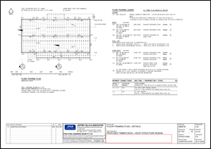
Access Sample A-04 here.
Roof framing plan
At times, roofs may either be solid concrete or steel deck (in both cases, the roof is considered a suspended floor) or composed of roofing components such as rafters or trusses. The example below shows the roof framing plan of the steel warehouse structure.[20] Construction personnel can refer to this section to identify roofing elements: purlins, rafters, ties, and bracings. The three tables at the bottom detail the structural purlin schedule, the structural framing schedule, and the steel column schedule. These inform construction personnel about the specifications and type of material to be used for the structural members.
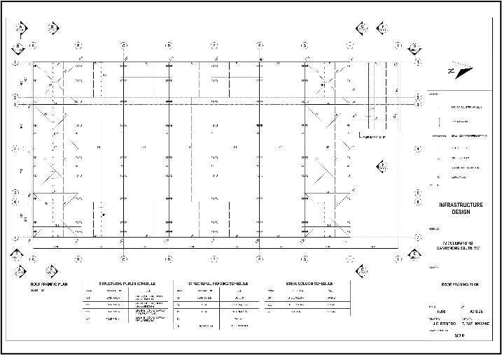
Access warehouse portal frame-01 here.
Connections and steelwork details
Connection details are drawings that specify what connection accessories or devices are to be used and how they should be installed on the site. Connection and steelwork details show the correct procedure for connecting steel elements such as rafters, struts, and ties and connecting steel columns into the concrete base. Additionally, it specifies the dimensions of the different connection devices, such as plates and bolts. Refer to the image below.[21]
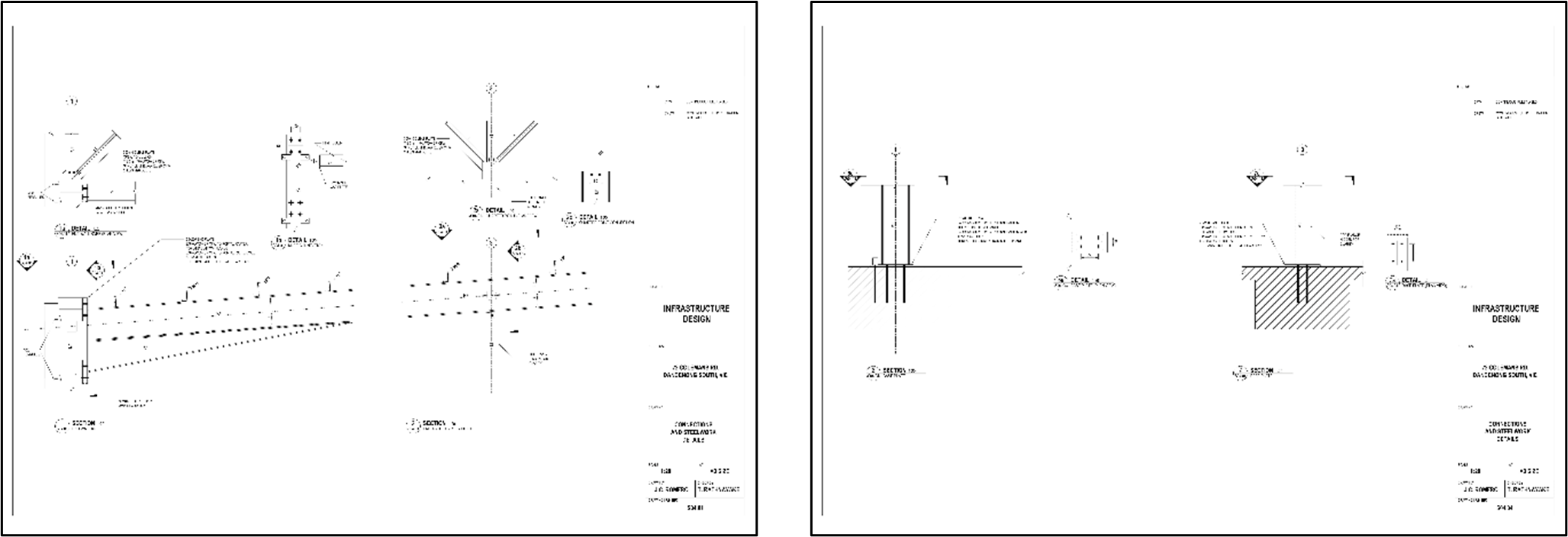
Access warehouse portal frame-04 and warehouse portal frame-07 here.
Any deviation of the actual conditions of the structural components from the structural drawings and specifications discovered during site work supervision or upon building inspection may be an indicator that the structural integrity is compromised.
As an example, let’s assume you are checking whether beams being installed comply with the provided specifications. To guide you in the inspection, you must reference the floor framing plan and specifications and pay attention to the floor framing legend on the right side of the document. Upon checking, you found out that a beam labelled as F.B3a is in a position labelled as F.B1 in the floor framing plan. You must immediately rectify this by replacing the erroneous beam and installing the correct beam, as specified. Failure to do so will compromise the structural integrity of the building.
Another way to ensure the structural integrity of components is by checking for any defects. As another example, when checking reinforced concrete columns, you discover extended cracks or find part of the cross-section is crushed. Both cases present a change in the original geometry of the column. Therefore, structural integrity is compromised. You must report to and coordinate with the appropriate industry professionals to develop solutions regarding the matter.
Building standards and codes
Australian Standards (AS) and Australian/New Zealand Standards (AS/NZS)
Australian Standards and Australian/New Zealand Standards contain up-to-date guidelines and specifications for construction. The difference between the two is that Australian Standards are developed solely by Standards Australia. In contrast, AS/NZS standards are developed through the collaborative efforts of both Standards Australia and Standards New Zealand. These standards are not mandatory but are recommended to ensure high quality construction work and processes. The NCC highly references Australian Standards.
Some of the AS and AS/NZS standards and codes relevant to building design and structural integrity are shown in the table below:
|
Standard |
Title |
|
AS 4100:2020 |
Steel Structures |
|
AS/NZS 5131:2016 |
Structural Steelwork – Fabrication and erection |
|
AS 3600:2018 |
Concrete Structures |
|
AS 4773.2:2015 |
Masonry in small buildings, Part 2: Construction |
|
AS 2870-2011 |
Residential slabs and footings |
|
AS/NZS 2327:2017 |
Composite structures—Composite steel-concrete construction in buildings |
|
AS 4440-2004 |
Installation of nail-plated timber roof trusses |
|
AS 1684-2010 |
Residential timber-framed construction |
Other Standards
Aside from the National Construction Code and Australian Standards, other codes and standards may also be used as long as an appropriate authority approves them. Some of these are listed in the table below.
|
Organisation |
Standard |
Title |
|
ASTM International (formerly American Society for Testing and Materials) |
ASTM E72-2015 |
Standard Test Methods of Conducting Strength Tests of Panels for Building Construction |
|
ASTM E695-2003 |
Standard Test Method of Measuring Relative Resistance of Wall, Floor and Roof Construction to Impact Loading |
|
|
National Association of Steel-Framed Housing (NASH) |
NASH Standard 2014 |
Steel Framed Construction in Bushfire Areas (incorporating amendment A) |
|
Standards Australia with International Organisation for Standardisation (ISO) |
AS ISO 9239 Part 1 (2003) |
Reaction to fire tests for floorings — Determination of the burning behaviour using a radiant heat source |
|
Cement Concrete and Aggregates Australia (CCAA) |
TN 61 |
Cement Concrete and Aggregates Australia — Technical note — Articulated walling |
|
International Organization for Standardization (ISO) |
ISO 2103:1986 |
Loads due to use and occupancy in residential and public buildings |
Government building and construction legislation and regulations
Government building and construction legislation and regulations contain provisions regarding matters related to building design and structural integrity and contracts, licences, registration, and other building legalities. Below is a table showing government legislation and regulations related to building and construction in each state or territory.
|
State/Territory |
Legislations/Regulations |
|
Queensland |
Building Act 1975 Building Regulation 2006 Queensland Building and Construction Commission Act 1991 Building Industry Fairness (Security of Payment) Act 2017 Queensland Development Code |
|
New South Wales |
Home Building Act 1989 Home Building Regulation 2014 Civil and Administrative Act 2013 Civil and Administrative Tribunal Rules 2014 Building and Construction Industry Security of Payment Act 1999 Contractors Debts Act 1997 |
|
Tasmania |
Building and Construction Industry Security of Payment Act 2009 Building Act 2016 Residential Building Work Contracts and Dispute Resolution Act 2016 |
|
Northern Territory |
Building Act 1993 Building Regulations 1993 Building (RBI and Fidelity Fund Schemes) Regulations 2012 Building (Resolution of Residential Building Work Disputes) Regulations 2012 Construction Contracts (Security of Payments) Act 2004 |
|
Australian Capital Territory |
Building Act 2004 Construction Occupations (Licensing) Act 2004 Building and Construction Industry Training Levy Act 1999 Building and Construction Industry (Security of Payment) Act 2009 |
|
Victoria |
Building Act 1993 Domestic Building Contracts Act 1995 Building and Construction Industry Security of Payment Act 2002 |
|
South Australia |
Building Work Contractors Act 1995 Building and Construction Industry Security of Payment Act 2009 Worker’s Liens Act 1893 |
|
Western Australia |
Building Act 2011 Building Services (Complaint Resolution and Administration) Act 2011 Building Services (Registration) Act 2011 Local Government (Miscellaneous Provisions) Act 1960 Home Building Contracts Act 1991 Construction Contracts Act 2004 |
Section Properties
Section properties are properties relating to the cross-section of a structural component. Basically, structural designers manipulate these section properties to calculate and achieve the correct design of members that can effectively resist tensile, compressive, shear, torsional, and bending stresses. Four commonly used section properties in structural design are the shape, centroid, second moment of area and radius of gyration.
Shape
Shape simply refers to the appearance or form of the face of the structural component. For concrete beams and columns, they could be square, rectangular, L-shaped, or T-shaped. Steel beams and columns are shaped according to established standards which includes I-shape and H-shape. Shape dictates the cross-sectional area, which plays a key factor in the structural capacity of the structural member. In a rectangular beam, the corresponding dimensions that define the area are width and depth.
Additionally, it is important to note that changing the shape's dimensions can significantly affect the material. For example, a rectangular concrete beam with a width of 25 centimetres and a depth of 40 centimetres becomes heavier when the width and depth are increased to 30 centimetres and 45 centimetres, respectively.
Centroid
The centroid is the geometric centre of a shape. In other words, it is the point at which the shape could be perfectly balanced when supported with the tip of a pin. For example, considering a square shape, the centroid lies at the point of intersection between two diagonals that run from opposite corners of the square. This is also the centre of mass for an object with uniform density and the centre of gravity.
Second moment of area
The second moment of area, also known as the area moment of inertia, is used in calculating the efficiency of the cross-section of a beam against bending stresses and deflection.
Radius of gyration
The radius of gyration represents the distance of a point from the centroid, which is used in determining the stiffness of the cross-section of a compression member (e.g. a column). It defines the efficiency of a cross-section to resist buckling stresses.
Effect of section properties on beams
Beams exhibit behaviours such as deflection and bending when subjected to imposed loads. The section properties of beams define how well the beam can resist bending stresses and avoid large deflections.
One example of how structural engineers utilise and manipulate section properties is by increasing the second moment of area. To increase the second moment of area, structural designers may increase the depth of the beam, resulting in an increase in the beam stiffness. This will allow the beam to resist a greater magnitude of bending stresses and large deflections.
To further explain this, take a plastic ruler, and with the flat side of the ruler facing down, hold both ends of the ruler with your hands. You are now simulating a simply supported beam. Using your hands, exert a small amount of bending force at the ends and see what happens. The ruler bends and deflects very easily. Now, try stacking a second ruler on top of the first one, and do the same process. Now, try stacking a third, a fourth, and so on. You will see that upon increasing the depth by stacking rulers on top of one another, the ruler does not bend as much as it had during the previous setups.
Effect of section properties on columns
Columns primarily exhibit compression under loads but may also bend and deflect, as mentioned previously, due to lateral loads such as wind and earthquake. Once again, the section properties can be manipulated to increase the compressive and bending capacity of the columns. The four section properties mentioned previously are equally important in the design of columns.
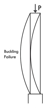
To further explain this, the ruler example can be used again. Take a plastic ruler and set it vertically on a surface, making sure to hold it at the bottom for support. Place a finger on the top end of the ruler, exert a slight downward push, and notice what happens. The ruler tends to bend on one side. In structural engineering, the ruler is considered a long column, which implies that the column will most certainly fail due to buckling.
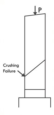
As mentioned, long columns are columns that will most probably experience structural failure due to buckling. To avoid this, a structural designer may increase the cross-sectional area of the column. In the ruler example, try stacking up more plastic rulers and apply the same force at the top end of the rulers. Notice that the ruler does not buckle as much as it had during the previous setups. Stacking more and more rulers increases the depth of the column, providing more stability against buckling until bending ceases to occur. The column is considered to be a short column, which are columns that will most probably fail due to crushing – a failure mode that is solely caused by pure compression.
The illustration below shows images of both crushing and buckling failure in columns.
HARRYS COMMENT: DIGITAL TEAM, CAN WE PLEASE RECREATE THE BELOW?
Effect of section properties on roof trusses
For roof trusses, the same concept from columns apply. It was discussed previously that truss members are considered two-force members, which means they only resist compression and tension forces. Generally, an increase in the width or depth increases the overall weight of the roof truss. From a structural design perspective, increasing either the width or the depth of a truss member in compression provides more stability against buckling. In the same way, an increase in either the width or the depth of the member allows for it to resist a greater magnitude of tension forces that tend to pull the member apart.
Structural performance is a concept that refers to the ability of a building component to perform its structural function. This includes the ability to resist structural design loads calculated based on industry standards and codes.
To ensure that structural performance complies with the NCC, it must meet both the General or Governing Requirements and the Performance Requirements. General Requirements and Performance Requirements will be discussed below.
General requirements of the NCC
- The General Requirements, also known as Governing Requirements, contain the rules and instructions for using and complying with the NCC. They serve as a guide in understanding how the technical requirements should be applied to any particular situation.
- In determining if structural performance meets the NCC General Requirements, you must review the General Requirements below and check if the building project follows these requirements. These are:
- Interpreting the NCC. This includes interpreting specific language and terms to understand the intended technical and legal meaning of the NCC, explaining the difference between the mandatory and explanatory parts of the NCC.
- Compliance with the NCC. This part explains the possible methods and pathways of demonstrating compliance with the NCC.
- Application of the NCC in States and Territories. This part explains applying the NCC in accordance with State or Territory legislation and its legal effects. It further explains the application of State or Territory variations, addition or deletions.
- Applying documents referenced in the NCC. This part explains how the NCC references other documents and how to adopt or apply them, since it does not contain details of every design and construction requirement for a building or plumbing or drainage system.
- Documenting the suitability of the design, construction and use of materials to comply with the NCC. This part explains the evidence needed to show that the NCC requirements are met and the solution is ‘fit for purpose’. This applies to materials, products, forms of construction and designs.
- Classifying buildings by their characteristics and intended use. This part explains how each building classification is defined and used in the NCC.
Performance requirements of the NCC

According to the NCC, a Performance Requirement means a requirement which states the level of performance which a Performance Solution or Deemed-to-Satisfy Solution must meet. It outlines the minimum necessary standards that different buildings or building elements must attain.
Compliance with the performance requirements can be done in three ways. These are Performance Solutions, Deemed-to-Satisfy solutions and a combination of the two.
Performance Solutions
Performance Solutions – These are tailored solutions to achieve compliance with the intended objective of the performance requirements. They can be verified by using one or a combination of the assessment methods listed below:
- Evidence of Suitability
- Expert Judgement
- Verification Methods
- Comparison with Deemed-to-Satisfy Provisions
Deemed-to-Satisfy Solutions
Deemed-to-Satisfy Solutions – These are solutions that can be achieved by following the Deemed-to-Satisfy Provisions, which include the appropriate materials, design factors, and construction methods to be applied. They can be verified using one or a combination of the assessment methods listed below:
- Evidence of Suitability
- Expert Judgement
Combination of Performance Solution and Deemed-to-Satisfy Solutions
Performance Solutions and Deemed-to-Satisfy Solutions can be combined to achieve compliance. It is important to note that the appropriate assessment methods must be used when using this combination compliance method. In other words, if a performance requirement is to be complied with using a Performance Solution, the corresponding assessment methods for a Performance Solution must be used. Otherwise, for a Deemed-to-Satisfy Solution, the corresponding assessment methods for a Deemed-to-Satisfy Solution must be employed.
NCC Assessment Methods
Below are the assessment methods mentioned previously and their corresponding descriptions.
Evidence of Suitability
Also known as ‘Documentary Evidence’, these are documents used to prove materials, products, construction methods, and designs are fit for their intended purpose and satisfy either a Performance Requirement or a Deemed-to-Satisfy (DtS) Provision. These may be one or a combination of:
- A report issued by an Accredited Testing Laboratory or a Registered Testing Authority;
- A certificate of Conformity or a Certificate of Accreditation;
- A certificate from a professional engineer, recognised expert or other appropriately qualified person;
- A current certificate issued by a product certification body that has been accredited by the Joint Accreditation System of Australia and New Zealand (JAS-ANZ); or
- any other form of documentary evidence that adequately demonstrates suitability, such as detailed manufacturer’s specifications.
Comparison with Deemed-to-Satisfy provisions
This assessment method involves analysing and comparing the Performance Solution with the DtS Provisions to determine whether the Performance Solution is better than, or at least equivalent to, the DtS Provisions. Technical analysis involving calculations and computer modelling may be used to prove compliance of the Performance Solution. If the Performance Solution is proven to be better than or equal to the DtS, then it is considered to comply with the NCC Performance Requirements.
Verification Methods
This assessment method involves establishing a quantifiable benchmark or predetermined acceptable criteria that the Performance Solution must achieve. Verification methods may take form in one or a combination of the following:
- A test – method used to verify whether a product meets the required performance level. (e.g. on-site thermal performance test of windows)
- An inspection – visual examination conducted by appropriately qualified personnel to check whether the construction or installation of a component satisfies the Performance Requirements.
- A calculation – engineering calculations that may involve computer modelling or hand calculations to prove that a design will achieve the expected objectives of the relevant Performance Requirements.
Verification methods for some of the Performance requirements are stated in the NCC. However, verification methods not found in the NCC may still be used as long as they are deemed acceptable by an Appropriate Authority.
Expert Judgement
This assessment method involves seeking expert opinion in cases where physical criteria cannot be tested or calculated. These experts may be qualified engineers or subject matter experts who usually possess accreditation from State and Territory accreditation bodies or registrars.
Although this assessment method is satisfactory, it falls to the Appropriate Authority to assess the expert’s credibility and to decide whether the expert judgement is acceptable or not.
This table shows where to find Structural Compliance requirements in the NCC.
|
Document |
Section/Part |
Description |
|
NCC Volume 1 |
Part B1 |
Structural provisions |
|
BP1.1 |
Performance Requirements for structural reliability |
|
|
BP1.2 |
Performance Requirements for structural resistance |
|
|
NCC Volume 1 |
BP1.3 |
Performance Requirements for glass installations at risk of human impact |
|
BP1.4 |
Performance Requirements for buildings in flood areas |
|
|
BV1 |
Verification Methods for structural reliability |
|
|
BV2 |
Verification Methods for structural robustness |
|
|
B1.0 to B1.6 |
Deemed-to-Satisfy Provisions
|
|
|
Specification B1.2 |
Deemed-to-Satisfy Provisions for design of buildings in cyclonic areas |
|
|
NCC Volume 2 |
Part 2.0 |
Application of Performance Provisions |
|
2.0.1 |
Application of part for Performance Requirements for Class 1 and 10 buildings |
|
|
Part 2.1 |
Structure |
|
|
P2.1.1 |
Performance requirements for structural stability and resistance |
|
|
P2.1.2 |
Performance requirements for buildings in flood areas |
|
|
V2.1.1 |
Verification Methods for structural reliability |
|
|
V2.1.2 |
Verification Methods for structural robustness |
|
|
Part 3.0 |
Structural provisions |
|
|
3.0.1 to 3.0.5 |
Acceptable Construction Practice
Structural software |
To ensure the accuracy of any analysis used to achieve NCC compliance and building design and structural integrity, you must confirm this analysis with relevant industry professionals.
Before you communicate and confirm with the relevant industry professionals, ensure that your analysis has laid out all the necessary information subject for confirmation. Your analysis should contain:
- The Performance Requirements for the building project, including:
- Bushfire Requirements
- High Wind Requirements
- Earthquake Requirements
- Alpine Environment Requirements
- The Performance Solutions applied to comply with the Performance Requirements for bushfire, high wind, earthquake and alpine environment requirements.
- The corresponding Australian Standards used in the Performance Solution
- Statements that explicitly indicate that Performance Requirements for bushfire, high wind, earthquake and alpine environment are met
- Explanation of the section properties of the building design elements and their effects on various materials
You must also prepare all the documents you have used as a reference in your analysis. These may be construction drawings, specifications, reports, certificates, tests, calculations, and other documentary evidence.
Below is the process of confirming your analysis with relevant industry professionals.
1. Identify the appropriate industry professional who can perform the confirmation. Refer to the table below for the relevant industry professionals, their job roles, and which parts of the analysis to discuss with the corresponding industry professional.
|
Relevant Industry Professional |
Job Role |
Relevant parts of the analysis |
|
Structural Engineers |
Responsible for designing the structural components of a building (e.g. columns, foundation), making sure that the building can withstand the magnitude of expected loads such as dead load, live load, wind load and earthquake load. |
|
|
Building Certifiers |
Responsible for inspection works of a building before, during and at completion, making sure that the building project complies with the approved plans and building codes and standards (e.g. access areas, bushfire compliance) |
|
2. Meet with the appropriate industry professional corresponding to the part of the analysis to be discussed. You may use the following communication methods:
- Face-to-face meeting
- Video conferencing
Alternatively, you may also communicate with the appropriate personnel through email. Remember to follow your organisation’s policies and procedures for contacting industry professionals.
3. Thoroughly present your analysis, as well as the documents you used as references (e.g. plans, reports, certificates) when you made your analysis.
4. Address any questions or clarifications that the appropriate industry professional may have regarding your analysis. Note down any suggestion or comments they have.
5. Having considered their suggestions or comments already, confirm if all details of the analysis are correct.
6. Record the verbal or non-verbal confirmation of the accuracy of the amendments of the appropriate personnel.
- For face-to-face meetings, record the conversation using meeting minutes documentation.
- For video conferencing, record the meeting using the video conferencing application used.
- For emails, keep a copy of the email correspondence.
Structural defects and their implications
Analysis of the structural integrity of a building requires the proper application of structural principles discussed earlier and the strict observance of relevant building codes and standards, as well as relevant building regulations and legislation. As construction personnel, it is always important to note that any deficiency in applying the factors mentioned may lead to structural defects that compromise the building's structural integrity. When structural integrity is compromised, remedial works are required.
It is essential to discuss this with relevant industry professionals since remedial works require technical expertise. Also, the extent of remedial work depends on the severity of the structural defect. The evaluation of the industry professional regarding the remedial work for a specific structural defect will give you an idea of the extent of the remedial work.
Structural defects are faults in structural components that arise due to any deficiency or deviation in the application of structural principles and may result in the destruction of a part or whole of the building. They may appear in the form of material deformation such as cracks, rust, and decay. Structural defects compromise the building's structural integrity, which may lead to a part or whole of the structure being prohibited from use. Thus, they require remedial works to restore their strength.
There are two main causes of structural defects:
- Failure to observe structural principles in structural design. This deficiency includes failure to observe relevant building standards and codes, erroneous structural design calculation, specification problems, and deficient loading criteria.
- Failure to observe structural principles in construction works. This includes the use of substandard materials and workmanship deficiencies.
The table below shows different structural defects and their corresponding implication.
|
Defect |
Implication |
|
Wide cracks in Concrete |
Structural failure due to structural member subjected to excess stresses not considered in the structural design |
|
Excessive deflection of beams/ceilings |
Structural failure due to structural member subjected to excess stresses not considered in the structural design |
|
Presence of termites |
Termites can eat away at support beams, wall studs, ceiling joists and more, causing a decrease in cross-sectional area and decreased structural strength. |
|
Sagging roofs & roof leaks |
Damage in roof trusses or the structure as a whole which may be due to lapses in structural design, termite damage, and incorrect installation/application of roof elements to prevent ingress. |
|
Uneven floors |
This could mean lapses in structural design or failure of foundation due to excessive settlement. However, this could also mean damage to supporting members (e.g. beams, columns) |
|
Damp sub-floors |
Sub-Floor lacks ventilation |
|
Timber rot |
Damp-Sub Floors; timber exposed to high moisture levels which promotes fungi growth |
|
Crumbling concrete or brickwork (Spalling) |
Exposure of concrete to high moisture or chemicals such as salts and chlorides |
|
Corrosion of Steel |
Exposure of steel to high moisture or chemicals such as salts and chlorides |
|
Ill-fitting doors and windows |
Possibly due to differential settlement of the foundation or any damage in components such as slabs, beams, or columns |
Extent of remedial work
The extent of remedial work depends on the severity of the structural defect present. The remedial works necessary may be extensive, complex, or costly. These may be categorised into the following:
Fundamental defect
This type of defect deems a building unsafe for use or occupation. It may require demolition or other procedures to replace a defective structural member or employ complex systems to restore the building’s strength.
Functional defect
A functional defect is a defect that affects the inhabitant’s beneficial occupancy of a structure or building. Unlike a fundamental defect, this does not prohibit the building from continuous usage and the remedial work necessary for this type is not as extensive as that for fundamental defect. However, this may still employ procedures for replacement or addition of minor structural members, materials, and systems to restore or improve strength. Although less severe than fundamental defects, functional defects must still be regarded with urgency to avoid the possibility of escalating into a fundamental defect.
Cosmetic defect
This type of defect does not affect the inhabitant’s beneficial occupancy of a structure or building. Thus, they are considered minor defects and do not require complex remedial work.
Industry professional consultation
The following is a list of industry professionals you need to consult and confirm analysis with when dealing with structural defects and the corresponding remedial works:
Structural Engineers
Structural engineers have the technical knowledge and experience to probe structural defects further and judge the best approach to remedial work. They may provide specifications regarding the methods of the remedial work required, materials and equipment to be used, and safety procedures.
Certified Building Contractors
Certified building contractors possess experience doing actual site works, which includes remediation of the structure. They may provide practical input to complement the structural engineer's concepts, thus coming up with better approaches and solutions towards remediating a defect.
Architect
Architects can be consulted when dealing with minor defects. In cooperation with structural engineers, they can recommend the material to be used for replacement or substitute to retain the aesthetic function of components.

Pre-commencement site inspection
In structural integrity analysis, there are two causes of structural defects: failure to observe structural principles in structural design and failure to observe structural principles in construction works. The former can be avoided by strictly observing and implementing the specifications provided by the NCC such as the acceptable construction manuals and practices stated and requirements for bushfire, high wind, alpine environments, and earthquake. Meanwhile, the latter can be prevented by proper supervision of construction works and conduction of pre-commencement site inspection.
Before conducting a pre-commencement site inspection, you must first collect and prepare the compliance analysis you made in the previous sections and outline the critical points of the analysis. You may do this in the form of a checklist.
During the site inspection, you must refer to the outline of the analysis (e.g. checklist). The outline or checklist should show elements of the site that are confirmed as being aligned with the analysis. Also, take note of all elements that are not aligned with the analysis.
Additionally, in a pre-commencement site inspection, you must ensure that it is a safe work environment. Aside from the fact that it is the law, a healthy and safe work environment promotes the efficiency of workers in carrying out procedures of installing and assembling structural components. In the long run, it prevents or minimises the likelihood of structural defects due to failure in observing structural principles in construction work.
With that said, a pre-commencement site inspection must involve careful examination of site elements including, but not limited to the size and terrain (e.g. flat, steep, irregular) of the work environment. This is especially important in evaluating the practicability of using heavy equipment. A small work environment may not permit entry of heavy equipment in the site. Otherwise, the workspace might become too congested; thus, reducing efficiency in construction work. In the case of the type of terrain, irregular terrain may not permit smooth access of heavy equipment across areas in the site unless site levelling procedures are to be employed first.
Another aspect that requires careful examination is the general condition of the work environment. General condition needs to be understood, for example, in the case of fabricating steel elements in either a controlled environment or open job site. To minimise or avoid possible structural defects due to faulty construction work, doing fabrication works in an open job site might be disadvantageous compared to doing works in a prefabrication facility. Thus, in the pre-commencement site inspection, you must carefully evaluate whether measures such as erecting additional elements (i.e. prefabrication or storage facilities) are necessary to promote quality work and avoid structural failure due to faulty construction works. In other words, the aim of a pre-commencement site inspection is to identify factors or elements that could affect structural site works and create safe and efficient systems based on these.
Other areas to consider during the pre-commencement phase include:
- Identifying possible design problems found on-site and bringing them to the attention of project consultants
- Establishing site access, temporary services, and appropriate location of on-site facilities
- Removal of existing services and hazardous materials in accordance with regulatory and environmental requirements
- Securing project plans and specifications
- Securing and reviewing various construction contracts
- Establishing workplace procedures and workplace safety
Approval project plans and specifications
Approval project plans are part of the whole project documentation, a set of official documents that serve as a basis for construction works and procedures, and a tracker for project progress and performance. Aside from approval project plans, project documentation includes:
- Structural designs and specifications
- Engineer’s footing design and specifications
- Registered plans
- Contour site plan
- Geotechnical report
- Underpinning, rock anchors and shoring design and specifications
- Retaining wall and tanking design specifications
- Structural, floor, wall and roof systems
Approval project plans and specifications refer to documents containing drawings, layouts, and specifications subject to approval by appropriate authorities or appropriate approval bodies. These documents are to be reviewed by the proper authority to ensure that all details and specifications provided are sufficient and comply with relevant building codes and standards before the commencement of any construction work.
Various construction contracts
Organisational quality documentation is a process that involves the preparation of legal requirements for a construction project. These requirements include construction contracts, policies, and procedures concerning work safety and the environment.
A construction contract is a legal agreement between contractors and employers regarding the specifics of construction work to be carried out and the supply of goods and materials.
Generally, there are two types of contracts. These are:
- Cost Plus – This is a contract wherein the owner or client pays the contractor for all expenses for the construction (e.g., materials, labour), plus an additional fee representing the contractor’s profit which may be a percentage of the cost or a fixed price.
- Fixed Price – This is a contract wherein the total cost for constructing a building is set under a fixed price agreed upon by the contractor and the client or owner. In other words, the building will have to be constructed within the agreed budget, and any costs incurred that goes beyond the budget will have to be paid by the contractor.
However, some construction contracts may be in the form of a combination of the two types stated above, for example, in the case of a cost plus contract with an agreed maximum price.
In some cases, construction contracts may be classified according to the setup or use. These are:
- Residential contracts – applies when constructing houses or dwellings for matters relating to residential construction works.
- Commercial contracts – applies when constructing commercial establishments such as shops, hotels, and others that are non-residential.
A subcontract agreement applies between the main contractor and subcontractor for specialised tasks or skills.
Australian Building Industry Contract
Australian Building Industry Contracts are contracts that architects can use to simplify the contract administration process. These contracts are created through the collaborative efforts of Master Builders Australia and the Australian Institute of Architects. The clarity and simplicity of such contracts minimises the likelihood of disputes between involved parties.
Several categories of ABICs are made depending on the size and nature of the construction work.
The table/figure shown below describes the different contracts:
|
Contract |
Description |
|
ABIC Major Works Contract (ABIC MW 2018) |
Lump sum contract for general non-housing projects with value between $500,000 and $3,000,000 |
|
ABIC Simple Works Contract (ABIC SW 2018) |
Lump sum contract for simpler non-housing projects with value between $500,000 and $3,000,000 |
|
ABIC Basic Works Contract (ABIC BW 2018) |
Lump sum contract for residential projects and some small commercial projects (up to $50,000) |
|
ABIC Early Works Contracts (ABIC EW-1 2003) |
Lump sum contract for projects related to site preparation (e.g. demolition, earthworks, excavation) |
|
ABIC Commercial Cost Plus Contract (ABIC CP-2014 C) |
A cost plus contract used by architects when there is a lack of details at the commencement of work. |
Notice that Major Works and Simple Works contracts are almost identical. The key difference is that Major Works Contracts contain provisions for contract mechanisms which Simple Works Contracts do not. These are:
- urgent instructions
- separable parts to the works
- change of type of security given by the contractor to the owner
- provision of security for payments for off-site plant and materials
- provision by the owner of security to the contractor
- dangerous or contaminated materials
- encroachments
- quality assurance systems
- separate contractors
- identified, project specific potential causes of delay that entitle the contractor to costs
- amendments to programs and the consequences of any amendments
- alternative dispute resolution
- expert determination of disputes
- arbitration of disputes
- contract confidentiality
Policies and procedures
The main difference between policies and procedures is that policies are general statements, while procedures are step by step instructions or guides. In general, policies and procedures refer to company documents that specify how work should be done and what standards of work, equipment and materials are required. Company policies and procedures are created based on state or territory laws and regulations. As well as compliance with the law, these documents ensure everyone in the workplace complies with company requirements.
Workplace procedures, workplace health and safety and environmental requirements
Workplace health and safety

Workplace health and safety (WHS) aims to uphold the protection of the health and safety of workers at work and others who might be affected by the work. It is based on the Work Health and Safety Act 2011, which is the basis of legislation for work health and safety throughout Australia.
WHS is essential because, first and foremost, it is the law. Secondly, worker health and safety promote the well-being of the organisation, as well as business performance. This means workers will be able to carry out their tasks efficiently and effectively.
The Construction Work Code of Practice is one practical guide that can be referenced to help you promote WHS in the workplace. In general, the Construction Work Code of Practice and other codes of practice are based on the Work Health and Safety Act 2011. According to the Construction Work Code of Practice, a pre-commencement document called the WHS management plan must be made. The WHS management plan is a document that lays out arrangements for managing some site health and safety matters and ensures that the required processes are in place to manage the risks associated with a complex construction project.
Environmental requirements

The following information is based on the Environmental Guidelines for Major Construction Sites published by the State of Victoria. This document serves as a guide in preparing and implementing an Environmental Management Plan (EMP) for major construction sites to avoid and minimise environmental impact, undertaking risk assessment and management, and ensuring that suggested environmental measures meet the performance objectives.
It is wise to incorporate environmental protection in the pre-commencement stage to ensure that practices can be built into the project design and work schedule. Environment protection practices involve environmental assessments. This involves identifying and understanding which parts of the environment may be vulnerable to damage from construction activities. Areas that are vulnerable to damage and require attention may include endangered flora and fauna, aquatic plants and animals, and groundwater recharge areas. Other areas to be considered include nearby residents or facilities such as schools and hospitals that may be affected by the impact of air discharges, construction noise, and vibration.
Therefore, the Environmental Management Plan (EMP) must be prepared by the contractor before work commences on any construction project. The EMP is a tool used to implement risk management measures based on prior site and risk assessments.
It is important to note the state or territory in which the construction project is located since environmental requirements vary based on the corresponding state acts and regulations. Refer to the table below for the environmental acts for each territory.
|
State/Territory |
Environmental Acts |
|
Australian Capital Territory |
Environment Protection Act 1997 Water Resources Act 2007 |
|
New South Wales |
Contaminated Land Management Act 1997 Dangerous Goods (Road and Rail Transport) Act 2008 Environmentally Hazardous Chemicals Act 1985 Forestry Act 2012 National Environment Protection Council (New South Wales) Act 1995 Ozone Protection Act 1989 |
|
New South Wales |
Pesticides Act 1999 Protection of the Environment Administration Act 1991 Protection of the Environment Operations Act 1997 Radiation Control Act 1990 Recreation Vehicles Act 1983 Waste Avoidance and Resource Recovery Act 2001 |
|
Northern Territory |
Environment Protection Act 2019 Environment Protection (Beverage Containers and Plastic Bags) Act 2011 Northern Territory Environment Protection Authority Act 2012 Waste Management and Pollution Control Act 1998 Environmental Offences and Penalties Act 1996 Litter Act 1972 Marine Pollution Act 1999 National Environment Protection Council (Northern Territory) Act 1994 Nuclear Waste Transport, Storage and Disposal (Prohibition) Act 2004 Water Efficiency Labelling and Standards (National Uniform Legislation) Act 2014 Water Act 1992 |
|
Queensland |
Biodiscovery Act 2004 Cape York Peninsula Heritage Act 2007 Coastal Protection and Management Act 1995 Environmental Offsets Act 2014 Environmental Protection Act 1994 Fisheries Act 1994 Forestry Act 1959 Lake Eyre Basin Agreement Act 2001 Marine Parks Act 2004 |
|
Queensland |
National Environment Protection Council (Queensland) Act 1994 Nature Conservation Act 1992 North Stradbroke Island Protection and Sustainability Act 2011 Queensland Heritage Act 1992 Recreation Areas Management Act 2006 Tweed River Entrance Sand Bypassing Project Agreement Act 1998 Waste Reduction and Recycling Act 2011 Water Act 2000 Wet Tropics World Heritage Protection and Management Act 1993 |
|
South Australia |
Aquaculture Act 2001 Environment Protection Act 1993 Radiation Protection and Control Act 1982 Wingfield Waste Depot Closure Act 1999 Local Nuisance and Litter Control Act 2016 Planning Development and Infrastructure Act 2016 |
|
Tasmania |
Environmental Management and Pollution Control Act 1994 Litter Act 2007 Pollution of Waters by Oil and Noxious Substances Act 1987 Water Efficiency Labelling and Standards Act 2013 National Environment Protection Council (Tasmania) Act 1995 Land Use Planning and Approvals Act 1993 State Policies and Projects Act 1993 |
|
Victoria |
Environment Protection Act 1970 Environment Protection Act 2017 Pollution of Waters by Oil and Noxious Substances Act 1986 National Environment Protection Council (Victoria) Act 1995 |
|
Western Australia |
Carbon Rights Act 2003 Contaminated Sites Act 2003 Environmental Protection Act 1986 Environmental Protection (Landfill) Levy Act 1998 Litter Act 1979 National Environment Protection Council (Western Australia) Act 1996 Waste Avoidance and Resource Recovery Act 2007 Waste Avoidance and Resource Recovery Levy Act 2007 |
Workplace procedures
States/Territories have different codes of practice. The codes of practice listed below are other relevant documents regarding construction workplace procedures applicable to the state of Queensland. The workplace procedures discussed are necessary in order to promote organisational quality.
- Concrete Pumping Code of Practice 2019
- Confined Spaces Code of Practice 2011
- Demolition Work Code of Practice 2013
- Excavation Work Code of Practice 2013
- First Aid Code of Practice 2014
- Formwork Code of Practice 2016
- Hazardous Manual Tasks Code of Practice 2011
- How to Manage and Control Asbestos in the Workplace Code of Practice 2011
- How to Manage Work Health and Safety Risks Code of Practice 2011
- How to Safely Remove Asbestos Code of Practice 2011
- Labelling of Workplace Hazardous Chemicals Code of Practice 2011
- Managing Noise and Preventing Hearing Loss at Work Code of Practice 2011
- Managing Risks of Hazardous Chemicals in the Workplace Code of Practice 2013
- Managing Risks of Plant in the Workplace Code of Practice 2013
- Managing the Risk of Falls in Workplaces Code of Practice 2018
- Managing the Work Environment and Facilities Code of Practice 2011
- Mobile Crane Code of Practice 2006
- Safe Design of Structures Code of Practice 2013
- Scaffolding Code of Practice 2009
- Steel Construction Code of Practice 2004
- Tilt up and Precast Construction Code of Practice 2003
- Work Health and Safety Consultation, Cooperation and Coordination 2011
- Traffic Management for Construction or Maintenance Work Code of Practice 2008
Building technology refers to tools, techniques, methods and processes used in the construction and management of building projects. As the standards for building performance have become more challenging, building technologies are continuously developed, and the demand for such continues to increase.
Before discussing the different examples of building technologies, you must first know the difference between new building technologies and emerging building technologies. New building technologies refer to recent technologies created within the last five years. On the other hand, emerging building technologies refer to technologies that may have been created and developed years ago but have only recently gained prominence in the building and construction industry.
The construction industry continues to evolve with the use of new and emerging building technologies. These innovations have improved the quality of construction work in terms of structural design, project planning efficiency, workplace safety, and cost efficiency. Refer to the tables on the following pages for some examples of new and emerging technologies and their descriptions.
|
New Building Technologies |
|
|
Technology |
Description |
|
Cloud Storage |
This is a tool that possesses the ability to store huge amounts of information via the internet. The advantage of using such technology is that information (i.e. project plans, construction drawings, reports) can be accessed by different people in different locations. Any updates to the data are also incorporated in real-time. |
|
Permeable Concrete |
This is a kind of concrete that absorbs large amounts of water within a short span of time. This can be applied in locations where flooding or heavy runoff occurs or when wastewater needs to be directed to the proper sewage. |
|
Machine Learning |
This technology can be programmed to complete repetitive construction tasks such as bricklaying and take in historical data that can be used to create more efficient ways to manage construction processes. |
|
The Internet of Things (IoT) |
This refers to tools or devices controlled by a central platform. Examples include smart devices for construction workers, which contain sensors that alert workers when guidelines are breached. |
|
Virtual Reality |
This technology allows construction processes, especially those that are dangerous, to be simulated. Additionally, it can simulate unexpected events such as natural disasters or major equipment malfunction, allowing users to take notes and gain insights from the simulations. |
|
Emerging Building Technologies |
|
|
Technology |
Description |
|
Aerial Drones |
This technology can be used to take aerial shots of the site, which can be used to monitor construction progress. More importantly, it can be used for monitoring site processes to look out for equipment malfunctions and work hazards that pose risks to construction site personnel. |
|
LiDAR |
Known in full as Light Detection and Ranging, this technology uses light to measure distances and gathers information from the light’s reflection from the surrounding site. It possesses the ability to produce 3D images based on the scan. |
|
Prefabrication |
Prefabrication is a method wherein structural elements (e.g. columns, slabs, beams) are manufactured off-site (i.e. manufacturing factories) and then transported and installed on-site. Although not necessarily a new technology, prefabrication is gaining back popularity due to high demand in fast and economical construction. |
|
Green Construction |
Green construction is a construction method that applies strategies to promote energy efficiency and conservation of natural resources. Like prefabrication, this is not a new technology; however, green construction is gaining popularity due to the high demand for energy-efficient construction and environmental legislation. Examples of this include rainwater harvesting systems and methods employing solar and wind energy. |
|
BIM Technology |
This is software that can be used as a collaborative platform for the various departments involved in construction (e.g. structural, mechanical, architectural, etc.). Using BIM, collaborators can point out conflict areas and easily incorporate revisions into the shared model. |
The discussion regarding the assessment of new and emerging building technologies and products is based on A Guide to Australian Building Product Conformity published by New South Wales Government. It serves as a guide in assessing whether technologies to be applied in building construction conform and comply with the NCC and other relevant Australia Standards.
The Building Product Supply Chain
The building product supply chain refers to the supply process of building products through the different branches involved. As construction personnel, you need to be aware of this to know the various personnel involved and their responsibilities. The image below shows a graphical representation of the building product supply chain.
HARRYS COMMENT: GRAPIC TEAM, COULD YOU PLEASE RECREATE THE BELOW?
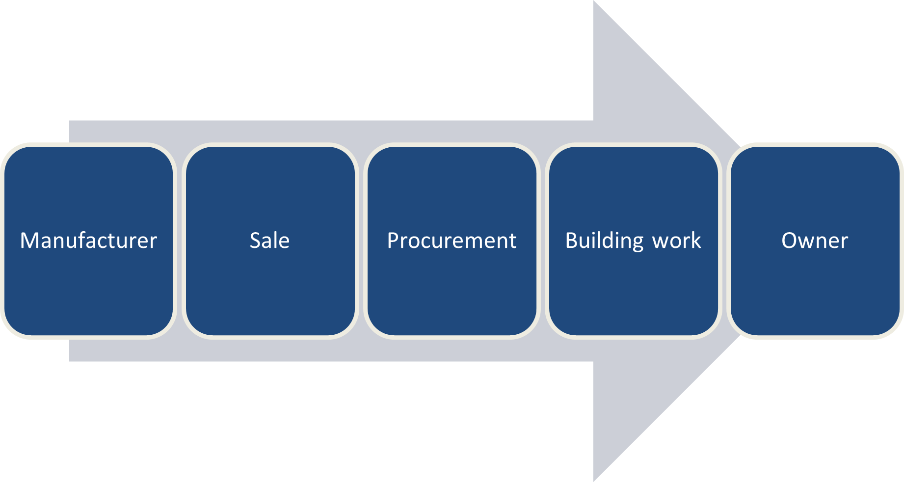
Based on the image, there are five branches involved in the supply process. Each division shares responsibility in assessing building products to ensure high quality and compliance with standards. These are:
Manufacturers
They must ensure product and material compliance and conformance with the NCC, standards, and local laws by providing required evidence in the form of product and material testing, assurance, and certification. In addition to that, they must provide specifications regarding how a product should or not should be used and supply the necessary compliance and conformance information, which includes limitations for each product and material.
Sale
Sale includes importers, wholesalers, distributors, and retailers. They ensure that their products and materials do not violate safety or performance based on trade or consumer laws or industry-specific requirements. Additionally, they should supply the necessary conformance information, including any limitations for each product and material.
Procurement
The procurement process includes building and construction industry professionals such as architects, designers, engineers, and other specialists. These professionals are responsible for ensuring that materials or products to be used are appropriately approved, ‘fit for purpose’ and meet the requirements of compliance and conformance requirements according to the NCC, as well as to relevant standards and laws.
Building Works
This branch includes builders, tradespersons, surveyors, certifiers, and approvers. The latter two ensures that plans and specifications comply with relevant codes, standards, and laws and look out for non-conformant and non-compliant products or technology to be used for construction works. On the other hand, builders, tradespersons, and surveyors must ensure that the products or materials to be used are suitable. They need to check that they are using conforming and complying products or materials since the risk and responsibility of using inferior products falls on them because they are the ones that do the actual building work.
Owners
Owners and occupants have the responsibility of understanding the consequences of using non-conforming and non-complying products or materials since they are the ones who ultimately use the finished structure. They may engage with competent experts or professionals to guide them.
Non-conforming and non-complying building products
To properly assess compliance and conformance of new and emerging technologies, you must know what non-conforming and non-complying products are. As the document states:
|
Non-conforming building products (NCBPs) and materials are those that: purport to be something they are not; do not meet required standards for their intended use; or are marketed or supplied with the intent to deceive those who use them. |
Non-compliant products (NCP) and materials are those that are used in situations where they do not comply with the requirements of the National Construction Code (NCC) other relevant laws and Australian Standards. |
In other words, non-conforming products are substandard products, while non-compliant products are used badly or incorrectly. Frequently, when there is a problem with a product, it is difficult to determine whether it is non-conforming or non-compliant, prompting further investigation or testing.
Compliance and Conformance with NCC and Australian Standards
As mentioned previously, the National Construction Code (NCC) provides the minimum requirements for safety, health, amenity and sustainability in the design, construction and performance of new buildings, including new building work in existing buildings.
In assessing new and emerging building technologies, requirements for compliance and conformance are contained in Part A2 of NCC Volumes 1, 2 and 3. Compliance and conformance are achieved when the Performance Requirements are satisfied.
HARRYS COMMENT: GRAPIC TEAM, COULD YOU PLEASE RECREATE THE BELOW?
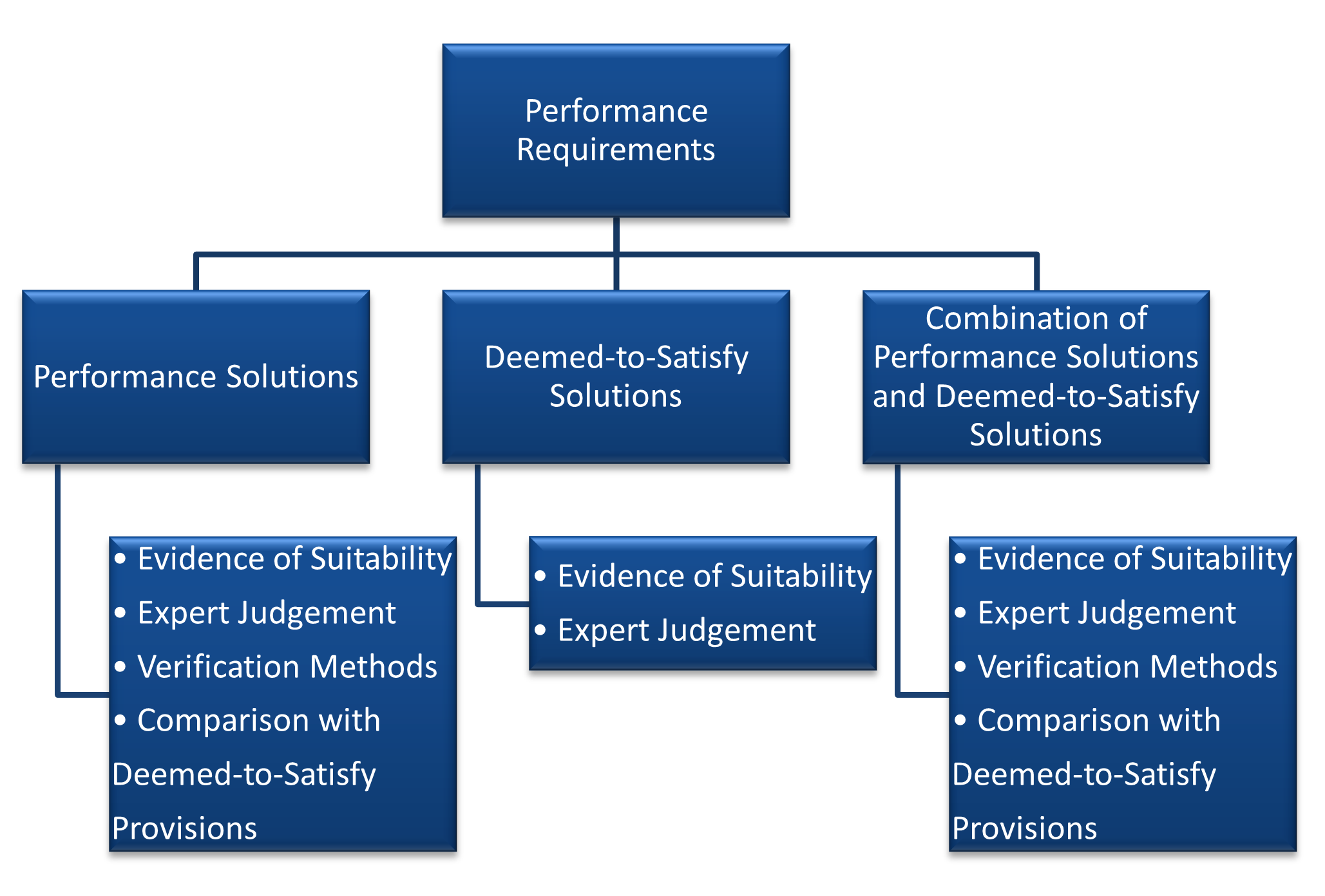
A Performance Solution provides a tailored solution to meet the intended objective of all applicable Performance Requirements. It is assessed using one or a combination of the following Assessment Methods:
- Evidence of suitability
- A Verification Method
- Expert Judgement
- Comparison with the Deemed-to-Satisfy Provisions
A Deemed-to-Satisfy Solution is achieved by following all appropriate Deemed-to-Satisfy Provisions, which are deemed to meet the Performance Requirements. It is assessed using one or a combination of the following Assessment Methods:
- Evidence of suitability
- Expert Judgement
When using a combination of solutions, the corresponding Assessment Methods must be used. This means that when employing a Performance Solution, you can choose either one or a combination of the four corresponding Assessment Methods stated previously. On the other hand, if a Deemed-to-Satisfy Solution is employed, you can choose either one or both of the two corresponding Assessment Methods.
Evidence of suitability provisions is included in the NCC as part of the supply chain process. This ensures that materials, design, and construction are fit for purpose and meet all relevant Performance Requirements or Deemed-to-Satisfy Provisions.
On the other hand, Australian Standards, published by the non-government standards organisation called Standards Australia, provides specifications and procedures to ensure safety, reliability, and quality performance of products and systems. The Deemed-to-Satisfy Provisions, mentioned earlier, commonly reference Australian Standards.
Types of evidence of product compliance and conformance
Assessing processes for conformance and compliance can be achieved by performing one or a combination of the following:
Testing. This process involves applying specific test procedures on a sample or a batch of materials.
Inspection. This involves an assessment of the design, production, installation, or performance of materials in situ.
Certification. Formal statements of compliance or conformity made by using a designated scheme or by an assessment body and based on the material evaluation. This includes:
- CodeMark or WaterMark Certificate of Conformity
- Certificate of Accreditation from a State and Territory Accreditation authority
- Certificate from a professional engineer or another appropriately qualified person
- Certificate from a product certification body accredited by JAS-ANZ
Declarations. Formal statements regarding the quality and performance of materials made by manufacturers or suppliers.
Regardless of the method used, this results in the issuance of certificates or other formal statements of the outcome. The assessment body should specify in the certificate or statement the method used, the performance requirement applied, and the result of the material assessment.
Independent ‘third party’ certification
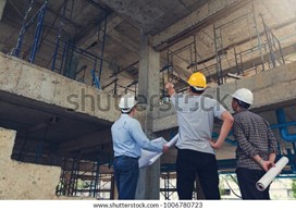
- This type of certification is recommended for materials or products which have a high risk of failure. This is performed by third party assessment bodies responsible for providing evidence of conformity and accredited by:
- Joint Accreditation System of Australia and New Zealand (JAS-ANZ) – for product certification, management systems, certification and inspection bodies
- National Association of Testing Authorities, Australia (NATA) – for testing and calibration laboratories and inspection bodies or
- accreditation bodies that are signatories to relevant international multilateral/mutual recognition arrangements and have the appropriate scope associated with the conformity assessment activity.
Product certification
There are two product certification schemes managed by the Australian Building Codes Board (ABCB) and these are both stated in the NCC. These are considered as evidence that a material or product complies with the NCC.
These are the following:
- CodeMark Certification Scheme (CodeMark). This is a voluntary building product certification scheme. As long as the product is used as specified, this certification verifies that the product complies with the requirements of the NCC.
- WaterMark Certification Scheme (WaterMark). This is a mandatory certification scheme for specified plumbing and drainage materials or products. The scheme ensures that these materials are fit for purpose and appropriately authorised for use.
Steps to ensure that products and materials are compliant and conformant
- Below is a checklist to guide you in analysing whether new and emerging building technologies are compliant and conformant:
- Check whether the specifications of the supplied material coincides with the specifications stated in the approved plans and specifications.
- Check if appropriate evidence of conformity and compliance is provided. Required evidence should be based on each construction product's intended use and risk exposure (likelihood and consequence of failure).
- If the evidence is not provided, suitable evidence should be obtained from the supplier. If evidence remains unavailable, conformity assessments including but not limited to, testing, inspection, or certification should be demonstrated.
- The material or product should not be used if the required compliance and conformance cannot be demonstrated.