Earthworks are the first phase of construction. It is critical since it involves methods and processes that can greatly influence the outcome of the project. It can be defined as a process that involves cutting, carrying, and filling material from one point to another for purposes such as set out, laying of foundation, and establishing the specified building elevation. The processes of earthworks are compaction, grading, and excavation.
Compaction
Compaction is the process of inducing stress to the soil to remove air voids and increase soil stability. The removal of air voids reduces water flow through the soil, and therefore increases soil strength and soil bearing capacity. This process is done with the use of heavy machinery that can perform compaction methods including but not limited to, vibration and rolling. This process is necessary to avoid problems such as foundation cracks caused by the settling of uncompacted soil.
Grading and Excavation
Grading is a process that involves either levelling the ground to a uniform elevation or setting the ground to a specified slope. Grading provides more stable support for foundations and is also used for drainage design to properly direct the flow of runoff water to prevent potential problems such as flooding.
In this phase, excavation follows cut-and-fill methods, transferring earth from one point to another for grading purposes. This may be carried out using simple tools such as wheelbarrows and shovels for small scale work. However, for large scale excavation, heavy machinery such as bulldozers should be used.
Excavation for foundation
Excavation for foundation is the process of creating cavities or trenches in the ground to lay out the foundation for the structure.
Geotechnical investigation and report
Prior to earthworks, necessary soil investigation procedures and testing must be done to determine the physical and mechanical properties of soil and the presence of geological faults and material deposits that influence soil behaviour and stability. This work is called a geotechnical investigation.
Geotechnical engineers carry out geotechnical investigations. In the final stages of the investigation, the data collected are interpreted to provide information to the structural engineer and other concerned construction personnel. This information is presented in a formal document called the geotechnical report. This document includes information such as the following:
- Level of excavation and slope of grade
- Degree of compaction
- Soil bearing capacity
- Cut and fill procedures
- Recommended foundation
Footings or slab configuration
Footing is an essential and critical part of a structure. Footing transmits the superstructure load (i.e. loads from roof, beams, floors, columns, and walls) down towards the soil foundation. They serve as the ‘foot’ of the building and must be designed and constructed to ensure that the building can withstand external forces. Thus, structural failure of footings may result in the fatal collapse of the whole building.
On the other hand, slabs are used as flooring systems for various occupancies, such as office and residential use. Although slabs can be suspended, meaning they are supported by columns or beams (i.e. floors above the ground floor), concrete slab floors can also be used as footings. Slab footings resist gravity loads, such as the weight of tiles, partitions, and people, as well as lateral loads from earthquakes or typhoons.
Bored pier footings
Bored pier footings are vertical columns that support and transmit the loads of the structure down to firm strata solely through bearing. This means that bored piers are designed for bearing only, unlike driven piles, designed to possess both bearing and friction resistance. In addition to that, pier footings are set at shallower depths compared to piles. The setting of bored pier footing involves boring and extracting foundation soil until suitable firm strata is reached.
In situations when bearing capacity is low, the base of bored pier footings may be increased in area, employed with concrete pad footings, or erected on pile caps for deeper depths.
The size and spacing of bored piers depend on the properties of soil, the magnitude of load, and the depth of excavation. Shapes include square, rectangular, and cylindrical. Bored pier footings can be made of the following:
- Masonry (bricks)
- Reinforced concrete – may be pre-cast (manufactured off-site) or cast-in-situ (assembled on site)
- Caisson – cylindrical support which may be constructed with an enlarged bottom or made of concrete-filled steel pipe
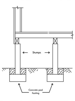
Column or Stumps
Column or stumps are the simplest footing used mainly for timber-framed houses and are considered shallow foundations. These are vertical supports that are usually square or rectangular in shape and made of materials such as timber, concrete, or steel. They disperse or distribute the loads from the column towards the foundation soil equally through a large area. Usually, the application of stump allows for adequate subfloor ventilation in timber-framed houses. Concrete pads support stumps at the base to provide stability against imposed loads.[22]
Concrete slab floors
Concrete slab floor is a type of foundation cast on the ground and used where a stratum of strong subsoil exists near the ground surface and when the ground is reasonably level or has a slope of up to 1 in 10.
It is not recommended to employ this type of footing system on steep or irregular ground since it tends to be weak and unstable on points where the slab may be suspended due to any irregularity of the ground surface. In this case, additional frame constructions are added to the design to provide strength and stability to the slab.
Concrete slab floor is composed of concrete and steel reinforcements that provide resistance against shrinkage stresses. This type of foundation is also known as slab-on-ground, and it can be incorporated with piers and beam foundations when necessary.
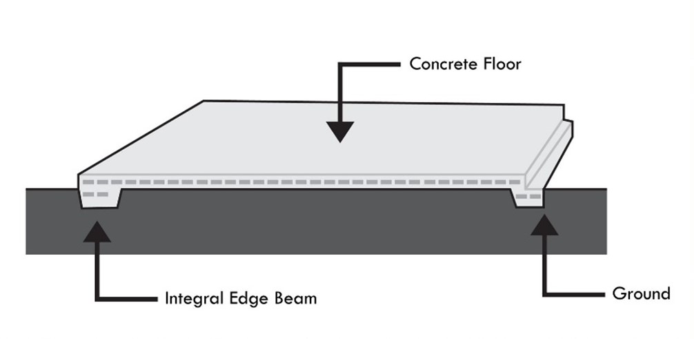
Concrete slab floors can be formed as a single layer of concrete. However, the edges of the slab can be increased to form edge beams that act as a footing to provide more stability against movement and other loads. Besides that, concrete slab floors are applied with gravel bedding for drainage and insulation for energy efficiency purposes.
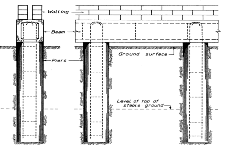
Reinforced piers and beams
A footing system of this type consists of concrete and steel reinforcements that resist bending stresses. Like stumps, reinforced piers and beams support a building above ground level and allows for ventilation with the space between the bottom of the beam and the ground. The reinforced beams carry the loads from the floor and transmit them to the reinforced piers. The piers then transmit these loads to the concrete pad upon which it rests, and finally, to the foundation soil.
Drilled and driven piles
Pile foundations are deep foundations typically made of reinforced concrete, steel, or sometimes timber. Piles are used mainly for reasons such as:
- to transfer loads to stable strata
- to reach depths far below the base of the structure to achieve stable footing
- to accommodate unequal building loads efficiently
Two methods exist in the application of pile foundations: drilled piles and driven piles.
Drilled piles
Drilled piles is a pile foundation application that involves using rotary boring techniques to create boreholes into the ground. After which, reinforcement can be set, and concrete can be poured into the borehole to form the pile. However, in cases where the soil is saturated with water, the sides of the borehole may collapse. As a solution, casings can be employed and inserted in the borehole before reinforcements and concrete are placed.
Driven piles
On the other hand, driven piles are a pile foundation application driven into the ground using a pile driver. Unlike drilled piles, driven piles are pre-fabricated piles, which means that concrete is cast before placement into the ground. These piles may be made of rectangular, round, or octagonal reinforced concrete, steel (e.g. steel pipes and standard beam sections), or wood.
One advantage of driven piles over drilled piles is that the pile driving method induces friction resistance between the skin of the piles and the soil in contact. Therefore, driven piles possess both bearing capacity and skin friction capacity. As a result, the load bearing capacity of the foundation increases.
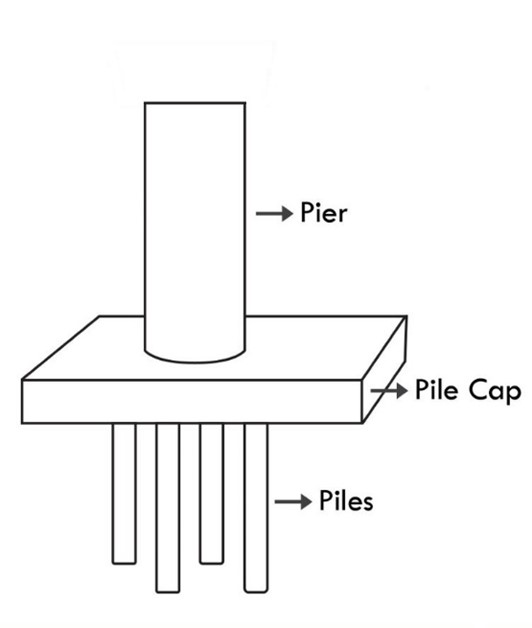
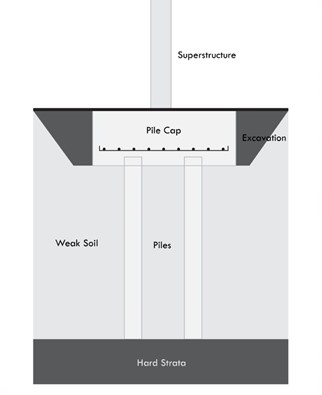
Piles are often grouped into clusters by a large reinforced concrete pad called pile cap into which the upper end of the piles are embedded. This serves as a support for other structural supports such as beams, slabs, or piers.
Mass concrete piers
The American Concrete Institute (ACI) defines mass concrete as any volume of concrete with dimensions large enough to require measures to cope with the generation of heat from cement hydration and attendant volume change to minimize cracking.
In other words, any structure that involves the use of large volumes of concrete is considered a mass concrete structure (e.g. dams). The natural process of heat of hydration in cement induces a rise in temperature inside the mass concrete. When the interior and exterior temperature of the mass concrete differ greatly, this could lead to the development of cracks. Thus, measures must be observed to minimise the cracking of concrete. The following are factors that influence temperature variation:
- size of structure
- ambient temperature (temperature surrounding the structure)
- initial temperature of concrete at placement and curing
- type of cement and cement contents in the mix
In the case of mass concrete pier foundations, measures should be taken to minimise cracking, which can greatly affect the strength of the foundation and the structural integrity of the building. These measures include:
- Using large size aggregates in the concrete mix
- Precooling the aggregates and the mixing water as a means of reducing the concrete mix temperature
- Employing chemical admixtures
- Employing pozzolan cement
- Adjusting the schedules of construction processes with seasonal changes
Screw piles
Screw piling is a deep foundation system that employs screw-in and ground anchoring methods to support a structure against compressive gravity loads, as well as uplift forces. It is done with the use of tubular steel hollow sections for the shaft and helical steel plates which are welded to the shaft. The helical steel plate placed near the bottom end of the shaft is designed according to the design load requirement, soil foundation parameters, environmental corrosion parameters, and minimum design life of the supported structure.
An advantage of using screw piles is that they can be used immediately to carry heavy structural loads once they are installed to the ground.
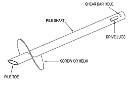
Image licensed under CC 3.0 source Screwpile Australia Diagram by Steve Lewenhoff
For more on screw piles watch the video below.
Waffle pod slabs
Like slab concrete floor, waffle pod slab is a foundation system that is constructed on ground and is suitable for level ground. Waffle pod slabs consist of setting a series of single-use plastic forms, or sometimes, evenly spaced Expanded Polystyrene square (hollow) blocks, which are poured with reinforced, post-tensioned, or fibre reinforced concrete slab.
Since this system is installed on ground, extensive excavation works and preparation are avoided. Structural advantages of waffle pod slabs include high resistance to ground movements due to the reduction in pressure from soil movement and high resistance against earthquake loads. Other advantages include reduction in the amount of concrete required, and built-in thermal properties.
Watch the below video on how waffle pods are installed on site.
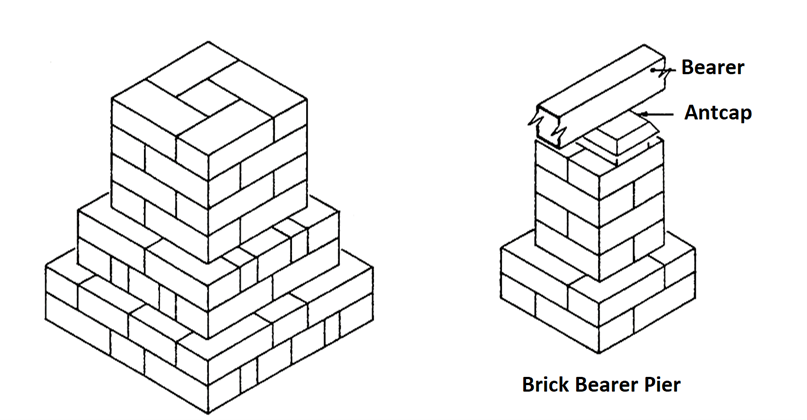
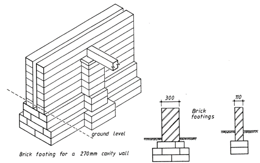
Brick bases
Brick base is a footing system which utilises masonry bricks. This material can be applied in column or pier systems. In addition to that, brick bases can be applied to strip footings as well, wherein it supports walls along the perimeter and walls found in the interior. Brick footings can be built in situ and are advantageous in remote sites where concrete transportation is difficult, and when labour and time for on-site concrete mixing are unavailable.
Structural advantages of brick bases include high resistance to fire due to their non-combustible property. Additionally, brick bases possess high compressive strength which makes them good for carrying heavy compressive weight.
Below are images of brick bases in pier applications.
Below are images of brick bases application in strip footing.
Cut and fill
Cut and fill is the process of removing, transporting, and depositing earth from one point to another to level the ground. A portion of land is cut to reduce the ground height to the desired elevation. Another portion of land is filled with the soil from cut land to raise the height to the desired level.
Watch the video below for a more simple animation of the cut and fill process.
Contour site plan
A contour site plan consists of a map or drawings representing the physical features of the ground on the site. These physical features include the profile of the land (e.g. slope steepness) and the corresponding elevations of points defined by contour lines based on an arbitrary datum or reference elevation. Contour site plans possess the following characteristics:
- Flat surfaces are represented by widely spaced contour.
- Steep ground is represented by closely spaced contour.
- Uniform slope is represented by equally spaced contour.
- Uneven surfaces are represented by irregular contours.
- A pond is represented by approximately concentric closed contours with decreasing values towards the centre.
- Hills are represented by approximately concentric closed contours with increasing values towards the centre.
- Ridges are represented by contour lines with U-shape with convexity towards lower ground.
- Valleys are represented by contour lines with V-shaped with convexity towards higher ground.
- Contour lines generally do not meet or intersect each other. However, if they intersect at a common point, it indicates the presence of vertical cliffs. If contour lines cross each other, it indicates the presence of an overhanging cliff or a cave.
Contour site plans are utilised for the following purposes:
- To have an idea of the nature of the ground (i.e. ridges, valleys, cliffs)
- To determine the ground profile for cut and fill calculations and procedures to be undertaken
- To determine the flow of runoff water. This is important in the planning and construction of appropriate drainage systems.
Below is an example of how a contour site map can be used in cut and fill procedure.
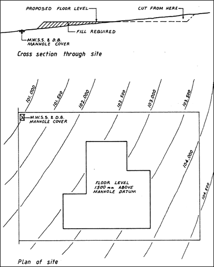
Based on the contour map sample, the contour lines are equally spaced and increases in value at regular intervals. The value represented by the contour lines indicates the height or elevation of points along the line. This contour presented in the contour site plan means that the ground profile is sloping gently and uniformly. To achieve the desired ground elevation, cutting of land can be done on land found at a higher elevation, as shown. The cut land can be deposited on low elevation areas to increase height to the proposed floor level.
Compliance with geotechnical report
To learn how to establish cut and fill, excavation, and compaction in compliance with a geotechnical report, a sample geotechnical report from the project entitled Proposed Shopping Centre Development will be used as an example. The document is available here.
Referring to the document linked above, specifications for cut and fill, excavation, and compaction are all stated in Part 6: Discussion. The parts preceding Part 6 contain general information about the project and technical procedures done during the soil testing. Compliance of cut and fill, excavation and compaction is achieved when specifications stated in the geotechnical report are observed and implemented.
Cut and fill specifications are stated in Part 6.1 Earthworks
- Utility trench excavations must be cut to competent bearing soils and backfilled with properly compacted Structural Fill.
- Materials selected for use as Structural Fill should not contain organic matter, waste construction debris, or deleterious materials.
- Fill materials should be granular material or be of low or medium plasticity.
- Existing onsite Fill meeting the above criteria may be used as Structural Fill.
- Under no circumstances should topsoil or other organic-laden soils be placed as Fill beneath or within 1.5 horizontal metres of building, car park, or other structural areas
- Once the final grade is reached in cut areas, and prior to Fill placement in areas of the site that will receive new Fill, the subgrade should be evaluated by a geotechnical engineer or their representative.
- Test rolling and Fill placement is to be undertaken under Level 1 Supervision.
Excavation specifications are stated in Part 6.2 Excavations. It specifies the following:
- For fill and natural soils, excavations can be done with the use of an excavator.
- Excavation of rock is expected to be required to achieve final subgrade elevation in the area of the proposed basement carpark.
- Assistance of ripper, rock hammer and rock saw are expected for this excavation.
Compaction specifications are stated in different subheadings of Part 6.1 Earthworks. These are:
- Fill materials should be placed in individual lifts of 300 mm or less loose measurement and compacted using a sheep’s foot roller for cohesive soils and a smooth drum roller for cohesionless soils.
- Where the use of full-sized compaction equipment is not possible due to confined space or other restrictions, thinner lifts may be required.
- ‘Bridging Lifts’ should not be used without approval by a geotechnical engineer.
- Fill should be compacted to a minimum of 98% of standard compaction with a moisture content within ±2% of the optimum moisture content.
- AS 3798-2009 Section 8.7 specifies compaction density testing of Fill at a frequency of 1 test per layer per material type per 2500 m2 or 1 test per 500 m3 distributed reasonably evenly throughout full depth for large scale operation such as the proposed development.
Assessment of the performance of footing elements can be done by referencing the relevant provisions and specifications in the National Construction Code. However, in order to assess the structural integrity of these elements properly, it is important to know and understand the concepts and processes related to the foundation.
Engineer’s footing design and specifications
Engineer’s footing design and specification refers to the drawings, details, layouts, section views, and specifications such as installation, material strength, dimensions, and design assumptions related to the foundation. In assessing the performance of footing reinforcement, concrete, and other components, this document serves as the basis, along with the relevant National Construction Code provisions. In assessing footing elements and checking whether a specific footing on-site is installed accordingly with the drawings and details specified. Engineer’s footing design and specification is an integral part of the structural designs and specification document discussed in Section 2.3.
Underpinning
Underpinning is applying modifications or additional structural methods to existing foundation elements to provide strength and stability for the structure. Underpinning procedures are performed when one or a combination of the following circumstances arises:
The foundation of an existing building is compromised or inadequate due to erroneous structural design or natural forces such as earthquakes, floods, and drought.
- Building usage or the occupancy changes, resulting in new and, possibly, heavier loads.
- Addition of new storeys to the building, either on top or below ground level.
- An adjacent or nearby construction disturbs the soil upon which an existing foundation stands.
- The properties of the foundation soil have changed or mischaracterised during the design.
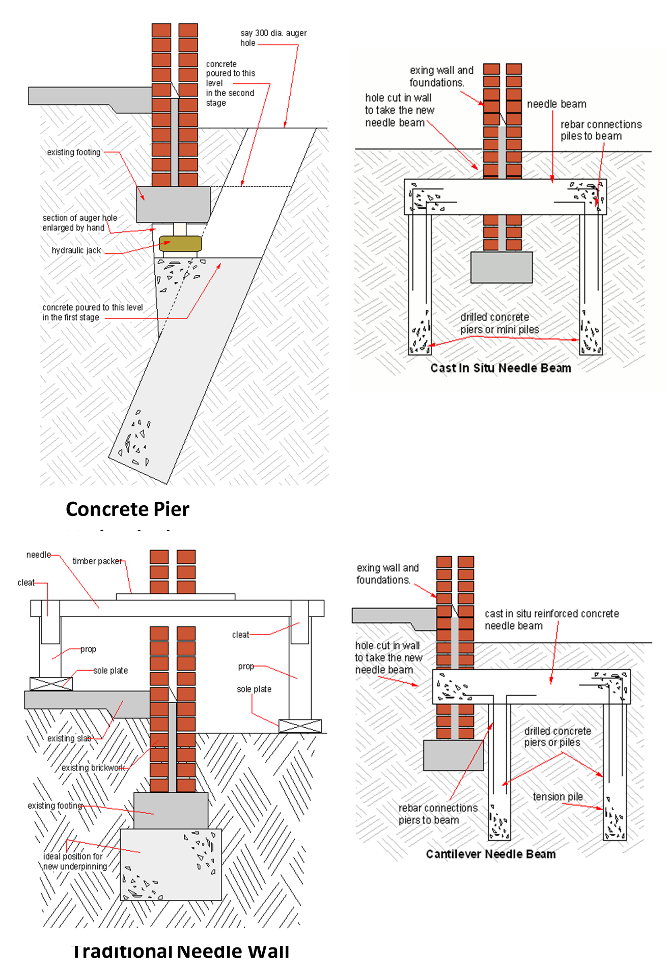
In underpinning procedures, footing elements may be enlarged to provide further stability for the structure, or the depth of the existing foundation may be increased by attaching extra supports or introducing new foundation elements underneath to reach a stronger soil stratum. In addition to that, the soil may be applied with grout or chemical treatment to increase its overall strength. Below are images of typical underpinning procedures.
Rock anchors
Rock anchors are devices used in the process of soil nailing. Soil nailing involves installing rock anchors that consist of steel bars inserted deeply into pre-drilled holes and grouted to bind the anchor and soil together. These rock anchors are installed closely at regular intervals and may rest upon concrete facing or shotcrete or a reinforcing mesh placed against the face of the soil beneath the head plates. The main purpose of soil nailing is to provide stability for unstable soil slopes or fractured rocks for retaining wall or embankment applications. Refer to the image below for soil nailing application in road widening construction.
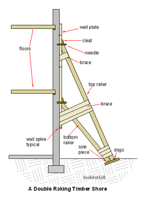
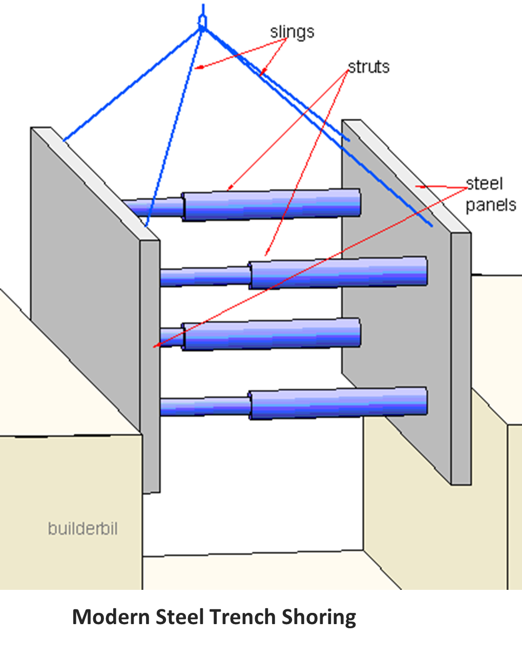
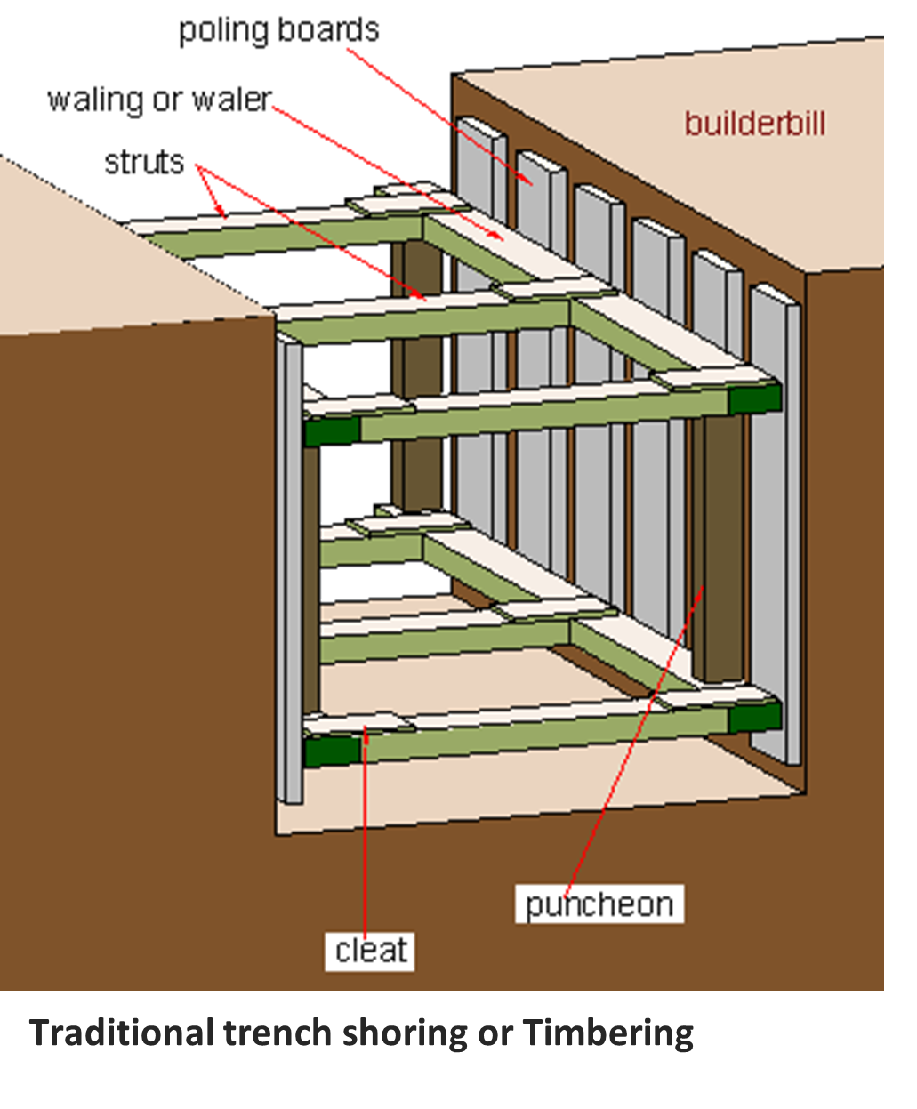
Shoring
Shoring is a construction process designed and employed to support the walls of an excavation to prevent it from collapsing. It functions similarly with rock anchors, providing stability for unstable soil slopes. However, the difference between the two is the method of supporting the soil. While rock anchors are concealed or embedded into the soil, some shoring applications are installed in a manner that occupies a large portion of the workspace for construction, which might be a disadvantage.
Examples of shoring applications include but are not limited to H-piles or soldier beams, sheet piling, raking shores, and hydraulic shoring. Refer to the images below for the types of shoring processes.
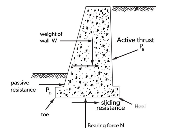
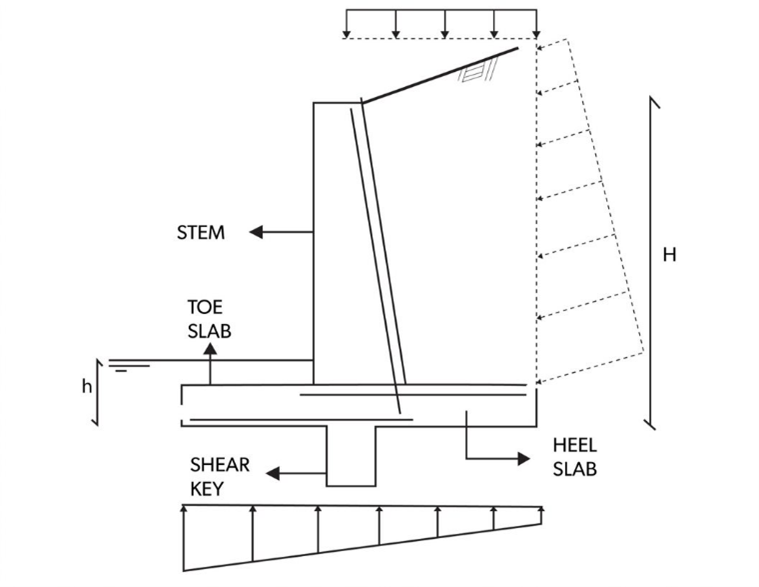
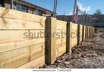
Retaining walls
Retaining walls are earth retaining structures. Their main function is to retain soil and prevent the catastrophic event of earth collapse. In a structural design perspective, it resists horizontal or lateral earth pressure induced by retained soil or any other backfill material. The practical application of retaining walls include basement walls and elevated parking lots.
Below is a table that shows the common types of retaining walls, the design specification, and example illustrations.
|
Type |
Design specification |
Illustration |
|
|
Gravity Wall |
|
|
|
|
Reinforced Concrete Cantilever Wall |
|
|
|
|
Type |
Design specification |
Illustration |
|
Timber Retaining Wall |
|
|
|
Type |
Design specification |
Illustration |
|
Brick Walls |
|
|

Tanking design specifications
Tanking is the process of applying waterproofing or moisture barrier on structural elements (e.g. basement walls, retaining walls). This is to protect the structure from the penetration of water into the interior. This process takes form in two methods: membrane or coating.
Tanking membranes are composed of plastic sheets fixed onto the internal wall face. On the other hand, coatings may be in the form of liquid applications of bitumen or asphalt, epoxy resins, or cement slurry.
The design specification for retaining walls and tanking procedures can be found in the Engineer’s footing design and specifications document, which is based on the provisions set by the National Construction Code.
NCC requirements
Together with the engineer’s footing design and specifications, NCC requirements must be referenced in the assessment of footing elements.
The table below shows the document, section or part, and a short description of the relevant NCC Volume 2 Requirements for foundation and footing elements.
|
Part/Section |
Description |
|
3.2 |
Footings and Slabs |
|
3.2.0 |
Acceptable Construction Manuals (application part) |
|
3.2.1 |
Acceptable Construction Practice (application part) |
|
3.2.2 |
Provides discussion regarding site classifications in accordance with AS 2870. It defines each site classes upon which the footing is to be located |
|
3.2.2.1 |
Sets provisions for preparation of footings |
|
3.2.2.2 |
Filling under concrete slabs |
|
3.2.2.3 |
Foundations for footings and slabs |
|
3.2.2.4 |
Slab edge support on sloping sites |
|
3.2.2.5 |
Stepped Footings |
|
3.2.2.6 |
Vapour Barriers |
|
3.2.2.7 |
Edge Rebates |
|
3.2.3 |
Concrete and reinforcing |
|
3.2.3.1 |
Concrete |
|
3.2.3.2 |
Steel reinforcement |
|
3.2.4 |
Site classification |
|
3.2.4.1 |
Site classification |
|
3.2.5 |
Sets the provisions for footing and slab construction. The topics that is relevant to the construction of footings are as follows: |
|
3.2.5.1 |
Footing and slab construction (size and placement of reinforcements) |
|
3.2.5.2 |
Footings and slabs to extensions to existing buildings |
|
3.2.5.3 |
Footings for fireplaces on Class A and S sites |
|
3.2.5.4 |
Stump footing details |
|
3.2.5.5 |
Sets the provisions for footing and slab construction. The topics that is relevant to the construction of footings are as follows: |
|
3.2.5.6 |
Footing and slab construction (size and placement of reinforcements) |
You can refer to the table below in determining compliance with the construction of footing systems.
|
Procedure |
Section |
Description |
|
Site Classification and Cut-and-fill Procedures |
3.1.1 |
Guidelines on safe construction procedures to avoid damage to the structure and the adjoining buildings and general requirements for earthworks such as site cut and fill procedures for unretained embankments. |
|
Excavation |
3.1.3.1 |
Requirements for excavation of drains adjacent to footings |
Listed below are standards relevant to the construction of footings.
- AS 2870-2011 Residential slabs and footings – This standard contains the provisions regarding the performance requirements and specific designs for common foundation conditions as well as guiding the design of footing systems using engineering principles.
- HB 28-1997 AMDT 1 The design of residential slabs and footings – This is a handbook that provides information and images regarding the characteristics of a building and site related to the footing system to be designed. Other details include building practices, alternatives for footing systems and house loading.
It is also worth noting the importance of the Excavation Work Code of Practice 2018. This contains workplace procedures and workplace safety methods in carrying out excavation works. The document is outlined in the table below:
|
Section Title |
Section |
Topics Covered |
|
Introduction |
Part 1 |
What is excavation work?; Who has health and safety duties in relation to excavation work?; What is involved in managing risks associated with excavation work?; Information, training, instruction, and supervision |
|
The risk management process |
Part 2 |
Identifying the hazards; assessing the risks; controlling the risks; maintaining and reviewing control measures |
|
Planning the excavation work |
Part 3 |
Principal contractor for a construction project; Designers; Safe Work Method Statements; Asbestos Licensing; Adjacent buildings or structures; Essential services; Securing the work area; Emergency Plan |
|
Controlling risks in excavation work |
Part 4 |
Excavated material and loads near excavations; Plant and equipment; powered mobile plant; Falls; Using Explosives; Atmospheric conditions and ventilation; Manual work |
|
Excavation methods |
Part 5 |
Trenching; Tunnelling; Shafts |
|
Preventing ground collapse |
Part 6 |
Ground conditions; Benching and battering; Shoring; Removal of shoring supports; Shields and boxes; Other ground support methods; Regular inspection |
Set-out is the process of marking the position of the building on the site. This includes the identification of boundaries, setbacks, building perimeter, and foundation excavation. Such a process is based on the details provided in the project plans and specifications.
Building set-out is critical since the processes directly influence the outcome of the whole project. Any errors made during the building set out may result in future alterations that might be costly.
Registered plan
One crucial legal document to identify building location boundaries is a registered plan, also known as a cadastral survey plan. This document is prepared by a registered cadastral surveyor and provides the details of the property such as the boundary lines, distances, bearings, and property area.
Procedures before building set-out
Before building set out is commenced, you should be aware of the preliminary procedures necessary. These are:
- Barricades (e.g. tape, plastic, and other temporary fences) and signs must be put up in order to restrict entry to an area. This is to isolate the area and promote safety on the site.
- Boundaries of the building location must be identified. This is important since boundary lines are established for legal ownership of land. The boundaries of the building area are determined by a licenced surveyor.
- You must be aware of the location of the verge, that is, the land located between the boundary and the street owned by the city or local council. Easements may contain sewers or stormwater pipeline underneath. No structure can be erected on top of an easement, and the verge must always be protected from any damage from building works since this land contains services such as electricity, water, gas, telephone lines, etc.
Building set-out process
Below is the process of building set out, which includes the process of the set-out of footings:
1. Identify the exact size and shape of the lot by applying on-site measurements. Mark the boundaries of the lot using boundary pegs and stringlines.
2. Identify and mark the approximate position of the building using temporary pegs. Building position is identified by its relationship (i.e. distance) to the boundary lines of the site. This includes identifying and establishing setbacks, which also serve as a guide in marking the building perimeter. Temporary pegs are stuck to the ground, starting with one corner of the building; the rest of the corners are marked by establishing the width and depth of the building.
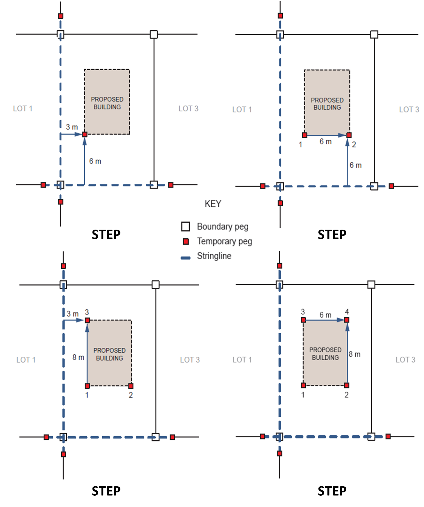
3. In cases where building shape is irregular, the process for establishing temporary pegs mentioned may still be applied since the pegs serve as a guide to the overall dimension of the building. Thus, at this stage, it is not necessary to map out the exact building shape.
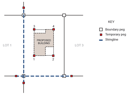
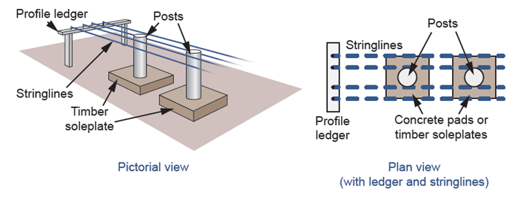
4. Outline the perimeter of the building with the use of profiles and stringlines. Profiles, also known as hurdles, consist of ledger and pegs made of either timber or steel, and serve as an anchor for stringlines. Profiles are also used to serve as a guide during excavation work so that the position of the excavation remains undisturbed. Profiles must be set-up using suitable level devices and at two to three metres from the building outline; however, it may be reduced depending on the site condition.
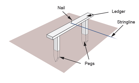
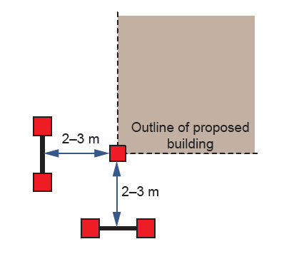
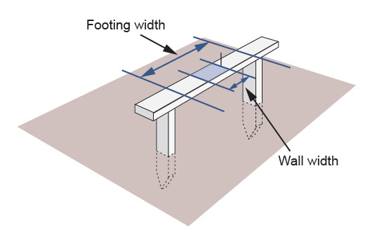
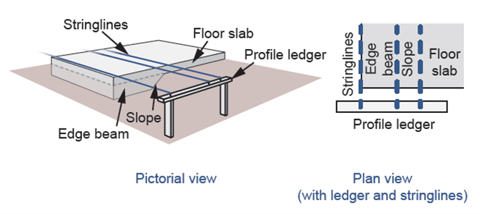
5. Using profiles, footings can now be set out. Ledgers can be marked with the width of the footing or other relevant information such as the width of the wall, position of columns or stumps, and many others. The image below shows the general idea of the use of profiles in footing set out.
Below are some examples of common footings used in Australia and the corresponding set-out details. Procedures can be applied for footings of similar nature.
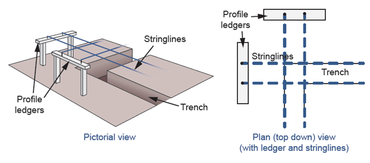
Strip Footing
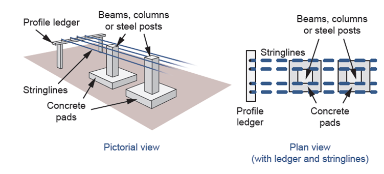
Concrete Pad Footing
Slab‑On‑Ground Footing
Stump or Post Footing