
Structural floor systems function to carry floor dead and live loads. They must therefore be designed to ensure stability, serviceability, and safety. In identifying flooring systems in project plans and specifications, basic knowledge regarding the materials, components, and configuration is necessary. The flooring systems discussed below will give you a picture of the concepts involved in each flooring system. They will guide you in identifying and understanding the type of flooring system specified in the project plans.
Suspended and slab on ground concrete floors
Suspended concrete floor is a flooring system made of concrete and supported by beams, columns, or walls at the perimeter or corners of the slab. This means that heavy loads can be carried by the suspended span of the slab and then transferred to beams, columns, or walls before going all the way down to the substructure. Since suspended concrete floors do not directly contact the ground, they are less likely to be exposed to damage due to dampness. In addition to that, suspended floors are constructed using temporary structures such as shoring and scaffolds to support it temporarily.
Suspended slab concrete floors could either be reinforced concrete or with the application of corrugated slab. The former is the traditional suspended floor system, employing both reinforcing steel bars and concrete as the main components of the flooring. On the other hand, the latter employs a corrugated steel tray or decking on which the concrete is poured. Although different in methods, both systems are similar in their use of steel, which improves the overall bending strength of the slab.
Meanwhile, slab on ground concrete floor is a flooring system wherein, unlike suspended concrete floors, the concrete slab is cast or place directly on levelled ground or soil. This means that the loads from the slab are transmitted directly to the foundation soil. Slab on ground concrete floors can be considered foundation or footing structures in the form of traditional reinforced concrete and waffle pod slabs. Since these structures are directly in contact with the ground, they need to be designed to resist damage induced by movements in the foundation soil so that stresses will not compromise the structural integrity.
Suspended timber, metal and steel floor frames
Suspended floor frame system is a floor system that can be made of either timber or metal (i.e. steel) and is supported by columns (i.e. stumps), walls (i.e. studs), or beams (i.e. joists and bearers). In western Australia, hardwoods such as jarrah, karri, Wandoo, and Blackbutt are used for timber floor, with jarrah being the most popular.
Steel floor frames consist of joists that can take on various shapes and are classified as ‘C’, ‘I’, ‘L’, and ‘S’, depending on their shape.
Steel floor frames are generally durable and, with little maintenance, can resist extreme weather conditions and serve its function for a long period over time without much damage. They also possess high strength-to-weight ratio, which means that structure can carry heavy loads while having a relatively low mass.
Additionally, another example of metal floor frames is aluminium raised floors. Due to the lightweight property of aluminium, these floor systems are generally light. Other advantages of this floor system include high resistance against corrosion and high strength-to-weight ratio, which means they carry heavy floor loads while having a low mass.
On the other hand, timber floor frames are generally good at resisting damage from fire. The outer layer of timber functions as an insulator against extreme radiant heat. It protects the core of the timber from being damaged quickly, which prevents the collapse of the entire structure.
Regardless of what material this floor system is made of, framing systems generally consist of the components shown in the image below.
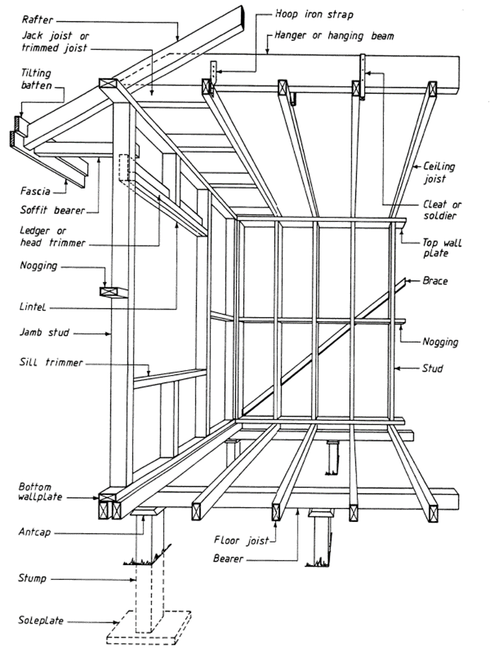
Floor system components and their functions are the following:
- Floor joists – serve as a support framework for the floor surface, either floorboards or sheet flooring.
- Bearers – serve as primary supporting members for floor joists.
- Ant caps – galvanised steel that serve as a barrier to prevent termite movement into the structure. They rest on top of stumps.
- Stumps – serve as vertical support for the bearers and function to create clear space between the ground floor and the soil.
- Sole plate – part of the foundation that functions to provide stability for stumps and distributes the load from the superstructure equally over a large area into the foundation soil.
Engineered floor joists
Engineered floor joists, also known as ‘I-joists’, are floor joists designed and processed to eliminate or minimise problems usually encountered using conventional wood joists such as bowing, crowning, twisting, and splitting. Engineered wood possesses excellent strength-to-size and strength-to-weight ratios and can carry heavier loads compared with conventional wood. These I-joists have two parts: the web and the flange. The flanges can be made from laminated veneer lumber (LVL) or solid wood finger. Meanwhile, the web, which is sandwiched between the two flanges, can be made of plywood, laminated veneer lumber, or oriented strand board. These components are assembled with water-resistant glue.
The main disadvantage of engineered floor joists is their weak resistance against fire. Direct fire exposure of I-joists leads to rapid structural failure or collapse.
In the application of engineered floor joists, you must be aware of certain actions that may negatively impact the structural integrity of I-joists. One action to consider is the process of cutting, notching or drilling the flanges of the I-joists. This action would reduce the overall strength of the joist, which affects the ability of the joist to resist structural stresses and effectively transfer the loads to the supports.
Another action that can negatively impact the structural integrity of I-joists is carrying the joists in the horizontal or flat position. I-joists are not suitable for carrying their own weight and other heavy loads in a horizontal or flat orientation. They must be in the proper orientation (vertical) when applied to resist the heavy floor loads. Carrying I-joists in a horizontal position would possibly lead to the weakening of the overall structural capacity of the joist and the displacement of the middle span of the joist due to deflection.
Refer to the video below to watch an overview of engineered floor joists.
Platform floor construction
Platform floor construction is a method of constructing floor framing systems wherein the whole floor is laid out first before the erection of walls and roof trusses. The main components of a platform floor are:
Pedestals
- Stringer bars
- Floor panels
- Floor Finish
- Floor boxes cut into the floor panels
In platform floors, the floor to be laid out serves as a platform for workers, to be utilised for construction works and procedures and for convenience and safety in the erection of wall framing.
The installation of wall framing and roof trusses comes after the installation of the whole floor level. This brings about a major disadvantage of platform floor construction. The absence of roofing exposes flooring components from damaging environmental factors such as rain, humidity, and sunlight. Thus, measures or procedures to protect flooring from deterioration must be considered. Platform floors also allow sound to travel through into other spaces or rooms, which may be a disadvantage in some cases.
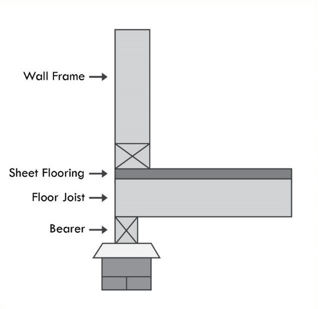
The image below shows the configuration of a floor system installed using platform floor construction, wherein the wall frame sits on top of the sheet flooring.

Refer to the video below to watch the process of platform floor construction.
Fitted (cut-in) floors
Fitted (cut-in) floors is a method of floor framing construction wherein flooring components are only installed after wall framing, and roof trusses are placed into position. In this construction method, floor installation is usually done towards the end of the job.
The main advantage of this method is that flooring components are protected from rain and sunlight due to the presence of a roof. Thus, the risk of damage to flooring components is eliminated or reduced. An advantage specific to the use of solid hardwood fitted floors is that they are generally good at resisting active loads such as heavy movement and foot traffic. On the other hand, engineered wood fitted floors are good for providing stability under heavy active loads and resisting damage brought about by temperature and moisture changes.
The image below shows the configuration of fitted floors.
Refer to the video below to watch the process of fitted (cut in) floor construction.
Compressed sheet wet area flooring
Compressed sheet wet area flooring is a flooring component applied in areas exposed to high levels of moisture, such as kitchens and bathrooms. Thus, these are floors sheets that possess high moisture resistance.
This type of flooring is commonly in the form of cement sheets or boards. Cement boards are composed of aggregated Portland cement with a glass-fibre mesh. They are highly water-resistant, which makes it very suitable for wet areas. However, although they are water-resistant, they still allow water penetration. Thus, additional waterproofing material has to be applied to prevent the passage of water.
Sheet flooring
Sheet flooring is a flooring component usually applied at the upper surface of a concrete floor or any flooring system and serves as the walking surface. Sheet flooring is more commonly in the form of particle boards.
Particle boards are engineered wood products applied with resins that make them weather resistant. These particle boards may also be manufactured to employ a tongue and groove interlocking system for better grip and stability. In addition to that, particle boards may be applied with methods to resist termite action.
Particle boards are susceptible to expansion and discolouration due to moisture. Thus, it is not wise to utilise them in high-moisture areas such as kitchens and laundries. However, if necessary, they can be treated with paint or other sealers or laid on top with moisture-resistant vinyl flooring.
Vinyl sheets can be used as sheet flooring. They are generally durable against high foot traffic and can last for years if installed properly and maintained.
Tongue and groove flooring
This type of flooring employs an interlocking mechanism called tongue and groove. These are usually applied in wood floorboards or panels, where one side has a protruding tongue, and the other has a receiving groove. The tongue and groove aids in eliminating unevenness in the floor level. To install wooden boards together, the groove of a plank is interlocked with the adjacent plank’s tongue.
Tongue and groove mechanism is very advantageous because it reduces the use of resources for nailing or adhesives in connecting the boards. However, tongue and groove flooring components need ptotection from damage caused by moisture.
Autoclaved Aerated Concrete (AAC) panel systems
Autoclaved Aerated Concrete panel system is an AAC floor application that employs the use of lightweight, precast, AAC units. These AAC units are composed of quartz sand, calcined gypsum, lime, cement, water, and aluminium powder and are manufactured in such a way to incorporate closed air pockets. Aside from floor panel systems, AAC is employed in structural wall systems, and wall cladding.
Aside from the ease and speed of installation brought about by its lightweight property, AAC panel systems provide excellent structural efficiency and sound and thermal insulation, which reduces heating and cooling loads in buildings. Additionally, it is fire resistant and provides great ventilation, which makes it a very desirable material for flooring.
Refer to the video below to watch the installation process of AAC floor and wall panels.
Types of footings vary considerably and include bored pier footings, columns and stumps, concrete slab floors, reinforced piers and beams, and drilled and driven piles. On the other hand, tie-down details refer to the procedures and accessories used in anchoring or connecting the main building frame to the footing or foundation to resist uplift forces due to wind forces.
The footing type and tie-down details are dependent on the flooring system employed in the project. Additionally, the type of footing to be established depends on other factors and considerations such as cost, availability of resources, and foundation soil strength.
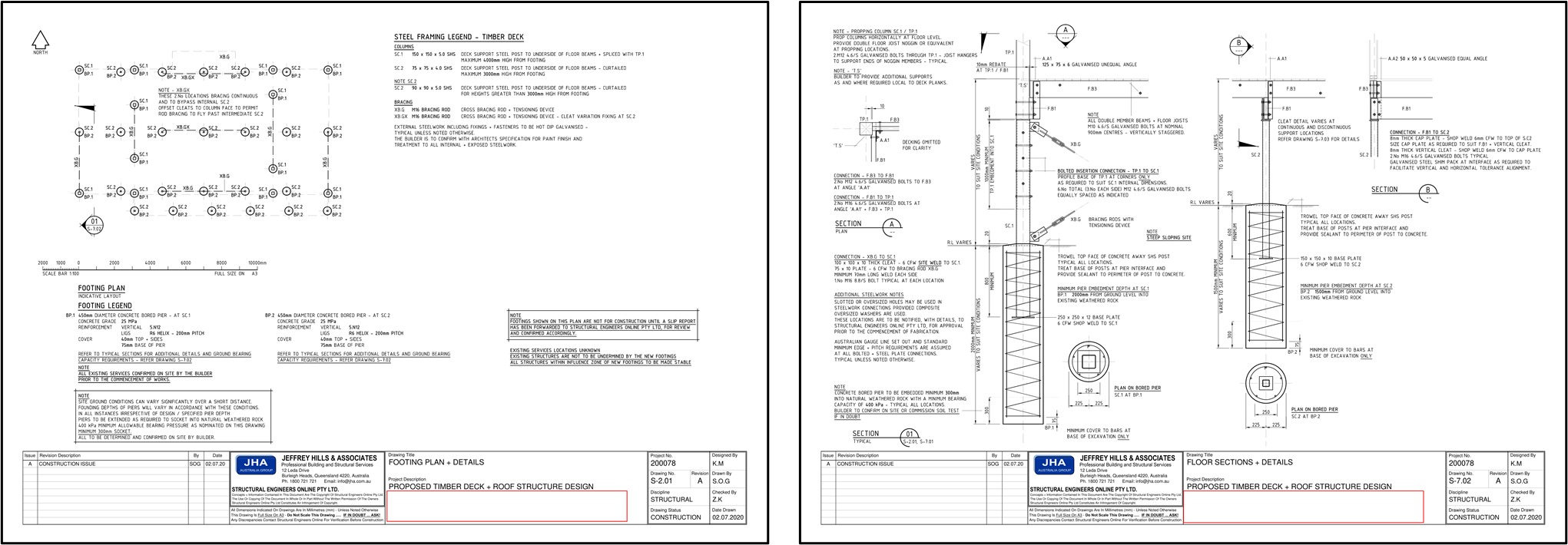
As you can see, the floor system employed in this sample project[36] is a timber floor system. For such a floor system, the suitable footing type established is a concrete bored pier system. Additionally, this employs columns made of steel sandwiched between the concrete pier and the timber frame. Refer to the images shown below. The left image shows the foundation framing plan, while the right image shows the tie-down details.
Access Sample A-03 and proposed Sample A-05 here.
As seen in many framed structures in Australia, columns or stumps with pad footing would have been an alternative for such building. However, it may not have been established due to factors present on site.
The footing and column specifications and details (e.g. dimensions, material) can be found in the samples. As stated under the footing legend, the footing type used is a bored concrete pier system while the steel columns, as stated under the steel framing legend, are SHS or Square Hollow Section.
The tie-down details are shown here.
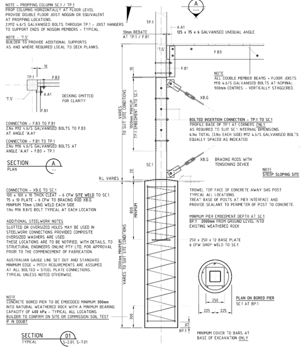
Contained in the red boxes shows the tie-down details between timber beams labelled F.B3 and F.B1 and tie-down details between beam F.B1 and timber post labelled TP.1. Bolts must be galvanised and sized as specified.
The green boxes show the tie-down detail between timber post TP.1 and steel column SC.1. The details show that the timber post must be embedded into the hollow steel column at the specified minimum height and that the embedment must be bolted as specified.
Lastly, the blue box shows the specification for embedment of the steel column SC.1 into the bored concrete pier, as well as the specification for embedment of the bored concrete pier from ground level into hard strata.
Remember that following the specifications in establishing footing type and tie-down details is critical. The foundation serves as the foot of the structure. Thus, any errors made in the establishment of footing type and tie-down details will be detrimental to the structural integrity of the building.
Steel flooring system
The NCC contains provisions regarding steel flooring system component compliance and span requirements. This is found in Part 3.4.4 Structural steel members. The tables for maximum acceptable spans for bearers, struts and lintels provided in the NCC can be used in assessing the compliance of floor system components to span requirements. To demonstrate the assessment, an example table will be used. Table 3.4.4.1a[37] shows the maximum acceptable bearer span (single span) for bearers supporting a timber floor and non-loadbearing stud wall.
Table 3.4.4.1a Maximum acceptable bearer span (single span) - bearers supporting a timber floor and non-load¬bearing stud wall
|
Steel Section |
1.8 EBS |
2.4 EBS |
3.0 EBS |
3.6 EBS |
4.2 EBS |
|
125TFB |
4.1 m |
3.8 m |
3.6 m |
3.4 m |
3.2 m |
|
180UB16.1 |
5.1 m |
4.7 m |
4.5 m |
4.3 m |
4.1 m |
|
200UB18.2 |
5.6 m |
5.2 m |
5.0 m |
4.7 m |
4.6 m |
|
250UB25.7 |
6.8 m |
6.4 m |
6.0 m |
5.8 m |
5.6 m |
|
250x150x9.0 RHS |
7.7 m |
7.1 m |
6.7 m |
6.4 m |
6.2 m |
|
250x150x5.0 RHS |
6.8 m |
6.3 m |
5.9 m |
5.7 m |
5.5 m |
|
310UB32.0 |
7.9 m |
7.3 m |
7.0 m |
6.7 m |
6.4 m |
|
125x75x2.0 RHS |
3.1 m |
2.8 m |
2.6 m |
2.5 m |
2.4 m |
|
125x75x3.0 RHS |
3.5 m |
3.2 m |
3.0 m |
2.8 m |
2.7 m |
|
150x50x2.0 RHS |
3.4 m |
3.1 m |
2.8 m |
2.7 m |
2.5 m |
|
150x50x3.0 RHS |
3.7 m |
3.4 m |
3.2 m |
3.0 m |
2.9 m |
|
100TFC |
3.2 m |
2.9 m |
2.7 m |
2.6 m |
2.4 m |
|
150PFC |
4.8 m |
4.5 m |
4.2 m |
4.0 m |
3.9 m |
|
180PFC |
5.4 m |
5.1 m |
4.8 m |
4.6 m |
4.4 m |
|
200PFC |
5.9 m |
5.5 m |
5.2 m |
5.0 m |
4.8 m |
|
250PFC |
7.2 m |
6.7 m |
6.4 m |
6.1 m |
5.9 m |
|
300PFC |
8.1 m |
7.6 m |
7.2 m |
6.9 m |
6.6 m |
Notes for Table 3.4.4.1a:
- EBS = Effective bearer spacing (m).
- Steel is base grade.
- Load must be evenly distributed along the member.
- See 3.4.2.3 for provisions that apply to suspended floors in single-storey and ground floor construction of suspended steel floor frames.
- Effective bearer spacing is a measure of the width of the load area being supported by the member (for single span members see Table 3.4.4.0a and Figure 3.4.4.0a).
Part 3.4.4 also shows the steel member abbreviations to further guide you in the assessment. These are:
- TFB — tapered flange beam
- UB — universal beam
- RHS — rectangular hollow section
- PFC — parallel flange channel
- TFC — tapered flange channel
- EA — equal angle
- UA — unequal angle
- SHS — square hollow section
- CHS — circular hollow section
For example, you are to assess the maximum acceptable bearer span of a steel member with the section 125x75x3.0 RHS used as single span for 1.8 EBS. By the simple method of tracing with the use the table provided, the corresponding maximum acceptable bearer span is 3.5 metres.
Timber flooring system
Timber flooring systems section compliance to span requirements can be assessed with the use of Australian Standard 1684.2 ‘Residential timber-framed construction.’ AS 1684.2 (2010) is composed of several supplementary documents, which are essential parts of the standard. These supplementary documents are categorised according to wind classification and the property of the timber to be used. The tables contained in these documents summarise section and span requirements.
The example below is taken from AS 1684.2 N1/N2 Supplement 2 (2010) ‘Residential timber-framed construction Part 2: Non-cyclonic areas N1/N2 Supplement 2: Timber framing span tables – Wind classification N1/N2 – Seasoned softwood – Stress Grade F7.’
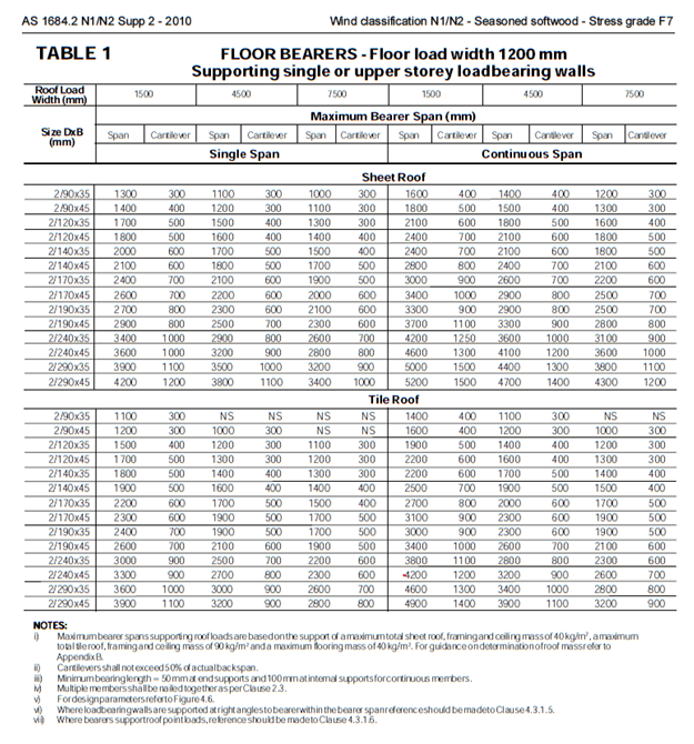
To assess section compliance to span requirements, you must be aware of the following:
- Floor load width – can be found at the main heading at the top
- Roof load width – can be found underneath the floor load width heading
- Size of the bearer – can be found at the leftmost column
- Manner of support – whether it is supported as a span or cantilever
- Roof material – whether the roof is made of sheet or tiles
Say, for example, you have a timber bearer with the size 2/90x 35 and possess the following data:
- Floor load width = 1200 mm
- Roof load width = 1500 mm
- Manner of support – span support
- Roof material – Tile roof
To determine compliance, find the bearer size and the corresponding span requirement. Therefore, based on the data at hand, a 2/90x35 bearer is required to have a maximum bearer span of 1100mm.
Floor framing and flooring should be compliant with NCC performance requirements for climate zone, fire resistance and rising damp.
Climate zone
The table below shows the document, the corresponding part or section number, and a short description of the relevant NCC Performance requirements for climate zones.
|
Document |
Part/Section |
Description |
|
NCC Volume 1 |
J1.6 |
Deemed-to-Satisfy Provisions for thermal construction for floors |
|
NCC Volume 2 |
3.12.1.5(a) |
Acceptable Construction Practice for thermal insulation for suspended floors |
|
3.12.1.5(c) |
Acceptable Construction Practice for thermal insulation for concrete slab-on-ground |
Fire resistance
The table below shows the document, the corresponding part or section number, and short description of the relevant NCC Performance requirements for fire resistance.
|
Document |
Part/Section |
Description |
|
NCC Volume 1 |
A5.4 |
Governing requirements for fire resistance of building elements |
|
C2.5 |
Deemed-to-Satisfy Provisions for compartmentation and separation of Class 9a and 9c buildings |
|
|
Specification C1.1 (3) |
Deemed-to-Satisfy Provisions for Type A Fire-resisting Construction |
|
|
NCC Volume 1 |
Specification C1.1 (4) |
Deemed-to-Satisfy Provisions for Type B Fire-resisting Construction |
|
Specification C1.1 (5) |
Deemed-to-Satisfy Provisions for Type C Fire-resisting Construction |
|
|
Specification C1.10 (3) |
Deemed-to-Satisfy Provisions for requirements in relation to fire hazard properties of floor linings and floor coverings |
|
|
Schedule 5 (d) |
Sets out procedures for determining the FRL (Fire Resistance Level) of building elements. Building elements meet the requirements of this schedule if they are designed to achieve the FRL in accordance with:
|
|
|
NCC Volume 2 |
Schedule 5 2(d) |
Sets out procedures for determining the FRL (Fire Resistance Level) of building elements. Building elements meet the requirements of this schedule if they are designed to achieve the FRL in accordance with:
|
|
Schedule 6 |
Sets out procedures for determining the FRL (Fire Resistance Level) of non-load bearing building elements |
|
|
3.7.4.3 |
Acceptable construction practice fire separation of garage top dwellings (separating floors) |
Rising damp
The table below shows the document, the corresponding part or section number, and short description of the relevant NCC Performance requirements for rising damp.
|
Document |
Part/Section |
Description |
|
NCC Volume 1 |
FP1.5 |
Performance requirements for rising damp (similar provisions as in P2.2.3) |
|
NCC Volume 2 |
P2.2.3 |
Performance requirements for rising damp |
Project documentation includes the structural designs and specifications document containing the drawings and specifications for flooring systems. This is used as a reference during the laying of specified floor systems to ensure that construction and installation is completed correctly.
For this section, the example to be used is the Proposed Timber Deck and Roof Structure. As shown in the floor framing & specification plan, the floor system employed in this project is a suspended timber floor system.[38]
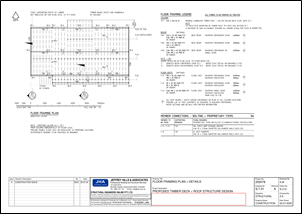
Access Sample A-04 here.
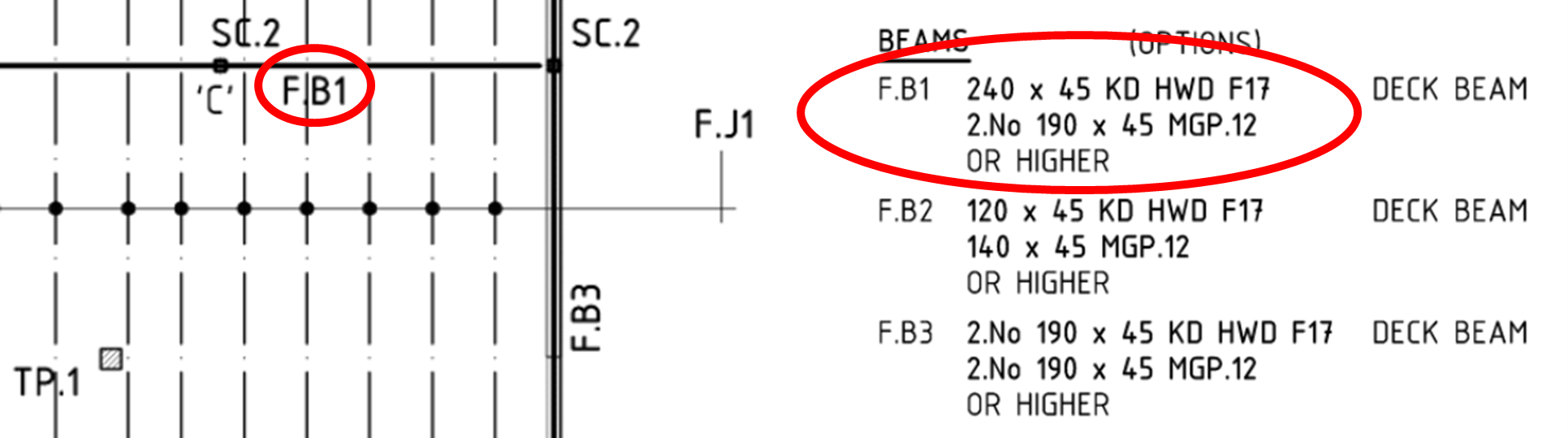
First, you need to make sure that the dimensions and specification of timber to be used for beams are in accordance with the plans. For example, timber beams labelled F.B1 must either be 240x45 KD HWD F17 or 2.No 190x45 MGP.12 or higher. Therefore, you must not use any timber that deviates from the specifications provided.
In the same way, you must make sure that the dimensions and specifications of timber to be used comply with the specifications provided. For example, floor joist labelled F.J1 must be 190x35 KD HWD F17 or 190x35 MGP.12 or higher. Otherwise, the timber will be considered non-compliant and may pose a risk to the structural integrity and safety of the whole structure.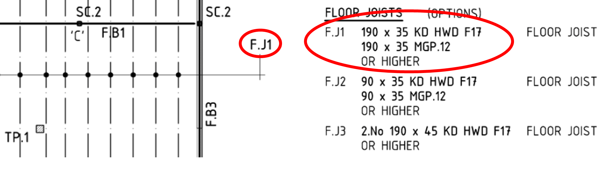
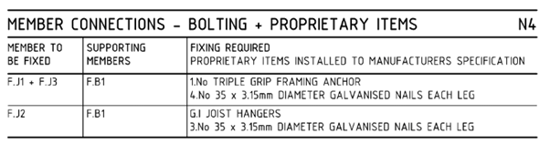
You must ensure that the actual layout of the floor framing members follows that which is specified in the floor framing plan. Check whether joists are spaced accordingly and that the connection or bolting requirements between members are made correctly. The specifications for member connections are shown below.
Aside from the structural components, you also need to make sure that elements for waterproofing and insulation components for floor systems and their installation comply with the project documentation. The details and procedures may be specified, or in some cases, the manufacturer’s specification may be referenced and regarded as a basis for the installation.
Watch the video below for the process of constructing a timber floor system.