In general, wall systems function as partitions or divisions in a building and, often, as the main vertical supports for overlying structural elements. There are two categories: structural and non-structural wall systems.
The main difference between structural and non-structural wall systems is their capacity to resist structural design loads. Structural wall systems are intentionally designed to carry loads transmitted from floor and roof systems, such as dead and live loads and lateral loads induced by earthquake and wind. On the other hand, although non-structural wall systems inherently possess a degree of structural capacity, they are not meant to carry loads, and they often function as aesthetic elements.
During the planning stage, the structural and non-structural wall systems employed for the building project are established. Your job is to identify the types of wall systems employed and analyse the pros and cons of such a wall system. This is to gain a deeper understanding of the configuration, such as the materials to be used and analyse the pros and cons.
It is important to remember that a wall system may be structural or non-structural regardless of its configuration or the material used. It depends on whether it was intended by the structural designer to carry loads or not. The following sections will discuss wall systems that are often considered as structural wall systems to aid you in identifying the type of wall system used for the building and construction project.
Composite walls featuring tilt-up slab, engineered timber products and lightweight AAC
Composite walls are walls built of two or more different types of materials combined. For example, a tilt-up slab wall may be employed for its strength and can be combined with engineered timber which serves as cladding for an extra layer of protection and visual appeal. The components of a composite wall depend on the specifications written by an architect or an engineer considering the intended purpose of the wall.
Below are some components that can be used to construct a composite wall.
Tilt-Up Slab
Tilt-up slab is a wall system that involves on-site casting of reinforced concrete wall panels. These walls are assembled and formed horizontally on a concrete slab or any temporary concrete casting surface. Concrete is then poured and allowed to cure before these wall elements are ‘tilted-up’ by cranes and braced into position. Other elements such as roof and floor can then be installed.
Additional loads brought about by processes such as lifting and handling should be considered in the design in tilt-up slabs. These factors are critical since these loads are just as important as the expected loads (e.g. dead loads, live loads) that a structure must carry.
The advantages of this wall system include the ease of installation, which promotes shorter completion time and reduced costs since transportation procedures are eliminated. Additionally, they also have a high thermal performance.
One disadvantage of tilt-up slabs that should be considered is their poor performance against earthquakes. However, a competent and experienced structural engineer may be consulted in order to ensure a safer and more stable design and eliminate structural issues that may require costly seismic retrofitting.
Engineered Timber Products
Engineered timber products are composed of wood products that are ‘engineered’ or processed to meet specific design specifications and satisfy international standards related to structural performance. These timber products can be used for flooring components, as well as wall systems. Examples of engineered timber products include glue-laminated lumber (glulam) and laminated veneer lumber. Glue-laminated lumber exhibits good structural performance in carrying heavy active and dead loads and possesses great tensile and compressive strength. On the other hand, the orientation of veneer layers wherein the grain of each layer goes in the same direction allows laminated veneer lumber to possess high overall strength. This allows laminated veneer lumber to carry heavier loads compared to regular timber.
The advantages of engineered timber products include various design options without compromising structural requirements, sustainability, easy to work with, and durability. On the other hand, disadvantages include the need for toxic adhesives and high energy requirements during the processing and manufacturing.
Lightweight AAC
Lightweight Autoclaved Aerated Concrete (AAC) panel systems commonly used for flooring, can also be used for wall systems. These lightweight AAC panels are manufactured in such a way as to incorporate closed air pockets.
Advantages of lightweight AAC include ease and shorter completion time due to its lightweight property, thermal efficiency, fire resistance, and termite resistance. Additionally, lightweight AAC possesses high loadbearing capacity and can support a structure up to two to three stories. However, the main disadvantage is its high degree of brittleness. This requires extra care in handling the material. Also, steel reinforcement should be incorporated to provide strength to the AAC and a protective finish to counter deterioration of the surface.
Framed Walls Incorporating Timber, Engineered Timber Products and Lightweight Section Steel
In general, framed walls are a type of wall system comprised of vertical and horizontal supports made of timber, engineered timber products, or lightweight section steel. Below are the descriptions each kind of framed wall mentioned.
Timber
Timber wall framing is a wall framing system that consists of timber sections for studs and other wall components. Advantages of using such framing system are strength, high fire resistance, and high thermal performance. The disadvantage of timber wall framing includes rot and infestation; however, this can be eliminated when proper maintenance is applied.
Engineered Timber Products
What sets this apart from traditional timber wall framing is the type of timber used. Engineered timber products are designed and processed to exhibit high structural strength and eliminate or minimise problems usually encountered using traditional timber (e.g. warping).
Lightweight section steel
Lightweight steel framing is also known as cold-formed steel frames. They possess excellent design flexibility due to their high strength-to-weight ratio, and they come in various profiles, including C-shape studs and U-shaped track. Compared to timber, lightweight section steel is lighter and stronger, and it is resistant to warping, shrinking, and damage due to termites. However, the main disadvantage of lightweight section steel is its weak resistance against fire. Measures and methods have to be applied to steel to make it fire-resistant.
Masonry walls incorporating cavity brick, single-leaf masonry and AAC
Masonry walls are walls that are composed of individual units bonded together with mortar to build a wall. These individual units may be made of bricks, concrete hollow blocks (CHB), stones, and AAC. Discussed below are the types of masonry walls.
Cavity Brick
Cavity brick wall is a wall system constructed by setting two parallel layers of brick walls separated by a small space or cavity between them. However, the separate walls are fastened together with metal ties to provide stability. These walls are called leaves of a cavity brick wall, with the inner wall as the inner leaf and the outer wall as the external leaf. They are generally more economical than solid walls and provide better thermal insulation due to the presence of the cavity, which reduces the transfer of heat from the exterior to the interior. However, this wall requires a high level of workmanship. Disadvantages of this type of wall include the possibility of metal tie corrosion and the fact that the thickness of insulation is limited by the width of the cavity.
Single-Leaf Masonry
As opposed to cavity brick wall, single-leaf masonry wall is composed of only one layer of brick wall. Thus, the single layer or leaf of brick wall acts as the exterior and interior wall. Although this means less cost and less space consumption, more efficient methods for insulation, weather protection, and other processes to increase the lifespan of the wall must be employed in this type of wall system.
Autoclaved Aerated Concrete
Masonry wall systems could also be made of Autoclaved Aerated Concrete (AAC) blocks. As mentioned previously, AAC is lightweight and possesses advantages such as high load bearing capacity, high thermal performance, fire resistance, and termite resistance. Of the three masonry wall systems mentioned, AAC masonry system is the best in terms of ease of construction and shorter construction time. This is due to its lightweight nature and natural property which promotes easy workability. However, due to their brittle nature, AACs need to be handled with care more than brick masonry.
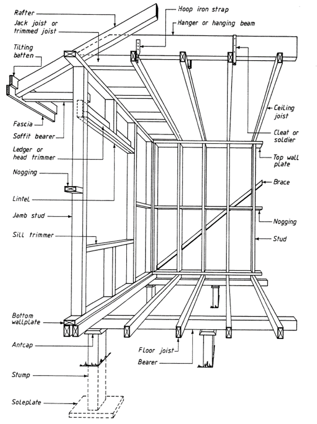
Timber and steel framing and structural steel members need to comply with performance requirements of the NCC and timber framing needs to comply with the AS 1684 Residential Timber-Framed Construction standard. This example drawing shows many of the framing parts.
Generally, wall framing consists of erecting vertical and horizontal supports made of timber or steel.
Below are the materials that comprise the wall framing and their corresponding function:
- Wall plate (top and bottom) – Top wall plate serves as a support for ceiling joists while the bottom plate serves as the base upon which vertical wall studs rest.
- Sill trimmers – These are placed over trimmed studs where windows or other openings are formed.
- Jamb studs – These are studs positioned to the sides of window or door openings.
- Studs – These are vertical supports spaced regularly and serve as support for wall sheeting and cladding.
- Noggings – These are pieces of timber or steel that have the same sectional size as the wall frame. These serve as horizontal stiffeners fit between studs, as well as additional support for wall sheeting materials.
- Brace – It provides rigidity and squareness of the wall from lateral forces. These are placed diagonally along the wall.
- Ledger or window head trimmer – It serves as material incorporated to add thickness to the lintel to make up for the wall's width. Additionally, this also used as support for jack studs and window fixing.
- Lintel – It provides support to the top wall plate located at an opening.
To determine compliance with the Performance Requirements of the NCC, you can refer to the table below that shows the document, relevant section or part, and a short description of the provision for timber and steel framing.
|
Document |
Section/Part |
Description |
|
NCC Volume 1 |
B1.4(c) |
Deemed-to-Satisfy provisions for structural resistance of materials and forms of construction for steel construction. It is determined in accordance with:
|
|
NCC Volume 1 |
B1.4(f) |
Deemed-to-Satisfy provisions for structural resistance of materials and forms of construction for timber construction. It is determined in accordance with:
|
|
F1.12(e)(iii) |
Deemed-to-Satisfy for subfloor ventilation. Provisions are similar to Section 3.4.1.2(e)(iii) of NCC Volume 1. |
|
|
Specification J1.2 |
Construction Deemed-to-Satisfy for Steel and Timber Framing Material properties in relation to thermal conductivity. |
|
|
NCC Volume 2 |
3.4.1.2(e)(iii) |
Acceptable Construction Practice for subfloor framing for ground or subfloor space subject to damp or frequent flooding
|
|
NCC Volume 2 |
3.4.2.0 |
Acceptable Construction Manuals for steel framing. Performance requirement 2.1.1 ‘Structural stability and resistance’ is satisfied if steel framing is designed and constructed in accordance with one of the following:
|
|
3.4.3.0 |
Acceptable Construction Manuals for timber framing. Performance requirement 2.1.1 ‘Structural stability and resistance’ is satisfied if timber framing is designed and constructed in accordance with the following, as appropriate:
|
|
|
3.4.4 |
Acceptable Construction Manuals for structural steel members. Performance requirement 2.1.1 ‘Structural stability and resistance’ is satisfied if they are designed and constructed in accordance with one of the following:
|
|
|
NCC Volume 2 |
3.4.4.1 to 3.4.4.4 |
Acceptable Construction Practices for structural steel members
|
|
AS 1684 |
|
Australian Standards 1684 ‘Residential Timber Framed Construction’ covers design criteria, building practices, tie-downs, bracing, and span requirements for timber framing structures.
The full provision for each document can be obtained from Standards Australia. |
In identifying processes for erecting structural and non-structural wall systems, you must outline the steps and use this outline later on during the implementation. Discussed below are general processes for erecting walls.
Composite Walls
For tilt-up walls, the general process is as follows:
- Once the foundation slab has been poured, the slab can be used as a working platform for the construction of tilt-up walls. Forms for the wall can now be set-up. Make sure that all openings on the wall such as windows and doors are considered, and that the forms properly outline the overall dimension of the wall.
- After the forms have been properly set, the main steel reinforcements and embedment for lifting and tilt-up procedures can now be installed. The bar sizes and spacing must be according to the project plans and specifications.
- The underlying slab is cleaned of any debris or obstruction and then poured with a specified concrete mix. The concrete is set for curing.
- Once the concrete has set, the wall panels are connected to the crane with cables and braces are attached. The crane then lifts the panel into position and it is then braced securely to the slab.
- Finishing procedure such as painting, sandblasting, and waterproofing can now be performed.
In checking the compliance to standards, you may refer to AS 3850-2003 entitled ‘Tilt-up Concrete Construction.’ This Australian Standard contains the requirements that need to be met in performing Tilt-up wall construction, such as transport, cranage, temporary storage, erection, and removal of temporary bracing.
For engineered timber (e.g. Oriented Strand Boards), installation involves proper alignment and correct drilling or screwing into the wall studs. In addition to that, cut edges must be applied with the necessary treatment to prevent damage from moisture.
Specific processes for the construction of Autoclaved Aerated Concrete walls are stated in Table 3.8.6.1c ‘Acceptable forms of construction for autoclaved aerated concrete walls.’ For concrete walls in general, processes are stated in Table 3.8.6.1b ‘Acceptable forms of construction for concrete walls.’
Framed Walls
In the erection of framed walls, you must first reference the manufacturer’s specifications since it provides a more detailed explanation, technical information, and specific steps regarding framed walls.
The general process is as follows:
|
1 |
2 |
3 |
4 |
|
The framer studies and interprets the drawing of the wall framing they are about to make. They take note of elements such as window and door openings, the presence of interior partitions, and corners where exterior walls are located. In general, exterior walls have a greater thickness to accommodate insulation while interior walls may be framed with a lesser thickness. |
The framer begins by marking all the stud and opening locations on the bottom and top plate. Corner posts, partition intersection, and full-length studs supporting headers over openings are to be cut first. The wall frame is then assembled while it lies flat on the floor platform. |
Studs are to be spaced at regular intervals are cut and assembled. They serve as support for wall sheeting. In the absence of a rigid wall sheeting, diagonal bracing, are to be installed. |
The wall is tilted-up into position and is secured against the floor. The framed wall must be temporarily braced for stability until all other wall framing components such as the upper floor framing and wall sheathing is complete. |
At all times, you must check each process by referencing all the relevant provisions stated in the NCC. Table 3.8.6.1d ‘Acceptable forms of construction for timber and steel framed walls’ shows specific processes for the construction of framed walls. A few of the standards mentioned in Section 4.2 that are relevant to wall frame construction are:
- NASH Standard ‘Residential and Low-Rise Steel Framing’
- AS 1684.2 ‘Residential timber-framed construction – non-cyclonic areas’
- AS 1720.1 ‘Design of timber structures’
It is also important to note that specific processes for constructing framed walls are shown in Table 3.8.6.1d ‘Acceptable forms of construction for timber and steel framed walls.’
Masonry Walls
The provisions for the acceptable construction of masonry walls are stated in Part 3.3 of the NCC.
The table below shows a summary of Part 3.3 to help you in checking compliance with the NCC.
|
Section/Part |
Description |
|
3.3.1 |
Unreinforced masonry (including masonry-veneer) must be designed and constructed in accordance with one of the following:
|
|
3.3.2 |
Reinforced masonry must be designed and constructed in accordance with one of the following:
|
|
3.3.3 |
Masonry accessories must be designed and constructed in accordance with one of the following:
|
|
3.3.4 |
Weatherproofing of masonry must be carried out in accordance with the appropriate provisions of one of the following:
|
|
3.3.5 |
Masonry veneer must be designed and constructed in accordance with one of the following:
Acceptable Construction Practice for Masonry veneer
|
|
3.3.5 |
|
In identifying and implementing processes for various masonry walls, you can refer to the NCC Volume 2 Table 3.8.6.1a ‘Acceptable forms of construction for masonry walls’ under Health and Amenity. This table includes cavity brick wall and single-leaf wall. Concrete blockwork is specified in Northern Territory Part 3.8.6 acceptable construction practice and found in Table 3.8.6.2 ‘Construction of walls to reduce impact sound and achieve a 50 Rw.’
Before going deeper into planning, implementing, and checking wall framing, you must familiarise yourself first with terms relevant to wall framing.
Bracing is a structural system employed in a building to provide added structural stability and rigidity against lateral loads such as earthquakes and wind. Wind bracings mainly resist wind loads and may be attached on roofs and on walls to prevent racking or side-to-side movements.
On the other hand, tie-downs in wall framing refers to the tools and accessories used in anchoring or connecting the wall frame to the main support (e.g. floor framing). This is to provide stability of the wall frame against uplift due to wind forces.
To avoid any confusion, you must know the difference between tolerances and allowances.
Tolerances are accepted limits of deviation from the original design. For wall framing, there are three primary considerations for tolerances.
- Vertical in-plane (plumb wall surfaces) – refers to the vertical straightness of the wall
- Horizontal in-plane (straight wall surfaces) – refers to the horizontal straightness of the wall
- Layout (location of elements) – refers to the position of wall components
In other words, tolerances account for any expected but unplanned deviations. For example, an eight-foot wall stud could still be considered plumb or vertically straight even when it has a one-fourth inch deviation for plumbness.
Allowances, on the other hand, are acceptable limits for planned deviations. For example, when holes are drilled into posts to insert wall components, the diameter of the hole must be slightly bigger. Otherwise, if the hole and the wall component to be inserted have the same sizes, it would be impossible to insert the component through the hole.
Planning for the use of wall frame elements and components includes being aware of the relevant Australian Standards and reviewing the manufacturer specifications that apply to the wall frame system used in the building project. This is to focus on the provisions that matter and eliminate those that are not relevant. This is especially beneficial in the implementation and checking stage since it helps in minimising the likelihood of overlooking important details during the application of such wall components.
The table below shows the document, part or section, and the description of relevant provisions you can reference to ensure wall component compliance.
|
Document |
Section/Part |
Description |
|
NCC Volume 1 |
Specification C1.11 |
Deemed-to-Satisfy Provisions for fixings and connection of external wall panels in relation to fire performance |
|
NCC Volume 2 |
3.4 |
All NCC provisions for framing are stated in this part. This includes:
|
|
NCC Volume 2 |
3.4 |
|
|
3.5.4.2 (c) & (d) |
Acceptable Construction Practices for fixings for splayed and timber weatherboards |
|
|
3.5.4.3 (c) |
Acceptable Construction Practices for fixings for wall cladding boards |
|
|
3.5.4.4 |
Acceptable Construction Practices for fixings for sheet wall cladding (i.e. fibre-cement, hardboard, structural plywood) |
|
|
3.10.6.4 |
Acceptable Construction Practices for Bracing. Figure 3.10.6.2 shows an illustration of bracing details of decks and balconies. |
|
|
3.12.3.5 |
Acceptable Construction Practices for construction of ceilings, walls and floors in relation to energy efficiency. This includes consideration for allowance for minimum lining movement gaps at wall, floor and ceiling junctions. |
Manufacturer specifications contain detailed information about the wall framing to be installed and specific steps for the whole installation process. As an example, the AusSteel Wall Frame Installation Guide is linked here. You must reference this to help you in the planning, implementing, and checking compliance for the installation of the wall frame and the components mentioned.
Refer to the table below for the summary of the document.
|
Section |
Description |
|
Section A: General Scope |
This section states the relevant Australian Standards and BCA requirements referenced and applied to ‘guarantee that the product’s full potential is achieved.’ In addition to that, the scope and limitations, as well as safety procedures, are set. |
|
Section B: Installation of Wall Frames |
This section contains illustrations and describes the process of erecting the wall frames, as well as applying the specified fixing, tie-downs, and bracing procedures. |
|
Section C: Preparing for fit-out |
This section contains provisions for implementing allowances and tolerances for services. Allowances and tolerances refer to holes or penetration for plumbing pipework, electrical cable work, communication lines, and openings for doors and windows. |
|
Section D: General Information |
This section contains provisions for on-site frame modifications in the occurrence of fabricating errors and fastening technical specifications. |
Wall framing in a building may be pre-cut and pre-nailed, factory pre-cut and assembled on-site, or cut and assembled on site. In a pre-cut and pre-nailed wall framing, portions of wall frame are entirely pre-fabricated, which means the components are cut and connected together in pre-fabrication facilities before being transported to the project site for installation. On the other hand, wall framing that is pre-cut and assembled on-site consists of components that are cut in pre-fabrication facilities. Pre-fabrication of frames allows for greater consistency and quality of processes and material. These components are then transported to the project site for manual installation.
Lastly, wall framing may be cut and assembled manually on site. Although cutting on site means having to deal with a large amount of waste, it allows for more flexibility in adjustments since on-site measurements can be easily performed. The following may be done to ensure the overall quality of the wall frame:
- Check if pre-fabricated frames follow manufacturer specifications.
- Make sure the length and height of the wall frame are correct.
- Make sure the dimensions of components used for wall frames are correct and appropriate.
- Check if all framing members are adequately connected to each other.
- Check if all members comply with section and span requirements.
- Make sure that all framing members are straight and plumb.
- Check if studs and noggins are properly spaced according to project documentation and specifications.
- Ensure that bracings are set at an angle according to the code and are sufficiently fastened to the top or bottom plates.
- Make sure that the wall bottom plate is adequately anchored or fixed to joists or concrete according to project documentation and specifications.
- Check if penetrations and openings comply with codes and specifications and window and door openings are located as specified in the plans.
- Check for defects that may have occurred due to transportation of components, exposure to moisture, etc. and apply specified measures to remove or mitigate the defect.
- Apply termite and weathering treatment to timber framing components
In the context of construction, services refer to systems installed in the buildings that provide building occupants with necessities that promote comfort, functionality, efficiency, and safety. These necessities include, but are not limited to, water supply, power supply, and ventilation systems. Below are three building services and their functions.
Plumbing Services
Plumbing services cover water services, sanitary plumbing systems, and drainage. Water services include the installation of both cold and heater water services, non-drinking water services, fire-fighting water services, cross-connection control, and rainwater harvesting systems. Sanitary plumbing and drainage systems include the installation of pipelines for wastewater. All design, construction, installation, replacement, repair, alteration, and maintenance provisions are all based upon the Plumbing Code of Australia 2019.
- Cold water services - AS/NZS 3500.1
- Heated Water services - AS 3500.4
- Non-drinking water services - AS/NZS 3500.1
- Fire-fighting water services - AS/NZS 3500.1
- Cross-connection control - Provisions for this matter are stated extensively in Part B5 of NCC Volume 3 Plumbing Code of Australia 2019.
- Rainwater Harvesting - Provisions for the installation of this system are stated in Part BP6.2. Buried and partially buried tanks are specified in B6.4, while pipework and outlet are stated in B6.5.
- Sanitary Plumbing System - AS/NZS 3500.2
- Sanitary Drainage System - AS/NZS 3500.2
Mechanical Services
Mechanical services are concerned with providing comfortable and safe heating, ventilation, and air-conditioning (HVAC) systems in the building. Requirements for mechanical services vary, depending on the state or territory you are on. As an example, the general requirements for mechanical services for Tasmania are listed below. These are based on Part ‘Tas G1.2 General Requirements’ of the Plumbing Code of Australia 2019 and shown here.[40]
(2)Mechanical ventilation and air-conditioning equipment must be in accordance with:
(d)AS/NZS 1668.1 for the use of mechanical ventilation and air-conditioning in buildings for fire and smoke control in multi-compartment buildings,
(e)AS 1668.2 for the use of mechanical ventilation and air-conditioning in buildings for mechanical ventilation,
(i)AS 4254.1 for flexible ductwork for air-handling systems in buildings,
(j)AS 4254.2 for the rigid ductwork for air-handling systems in buildings
(m)AS 5601 for gas installations.
Electrical Services
Electrical services are generally concerned with the proper and safe installation of electrical elements in a building. This provides a power supply, a backup power supply, and an emergency power supply. Australian Standards for Electrical Installations AS/NZS 3000 (2007) is one document that is used for reference.
The NCC Volumes 1 and 2 provide a discussion regarding the installation of services. Refer to the table below for the document, relevant part or section number, and a short description of the section.
|
Document |
Part/Section |
Description |
|
NCC Volume 1 |
CP8 |
Performance Requirements for fire protection of openings and penetrations |
|
C3.9 |
Deemed-to-Satisfy Provisions for service penetrations in fire-isolated exits |
|
|
NCC Volume 1 |
C3.12 |
Deemed-to-Satisfy Provisions for openings in floors and ceilings for services. This is in relation to fire resistance. |
|
C3.15 |
Deemed-to-Satisfy Provisions for openings for service installations. This is in relation to fire resistance. |
|
|
Specification C1.1 (2.4) |
Deemed-to-Satisfy Provisions for method of attachment to not reduce the fire-resistance of building elements |
|
|
Specification C3.15 |
Deemed-to-Satisfy Provisions for penetration of walls, floors and ceilings by services |
|
|
Specification E1.5a (3)(a)(ii), (3)(b)(ii), and (3)(c)(ii) |
Deemed-to-Satisfy Provisions for permitted concessions related to service penetrations and fire safety |
|
|
Specification E1.8 (7)(a) |
Deemed-to-Satisfy Provisions for openings in a fire control room in relation to services |
|
|
FP5.3 |
Performance Requirements for sound transmission through floor and wall penetrations and door assemblies |
|
|
FP5.3 |
Performance Requirements for sound transmission through floor and wall penetrations in residential care buildings |
|
|
F5.2 (2)(e) |
Deemed-to-Satisfy Provisions for services in relation to sound insulation for building elements. |
|
|
NCC Volume 2 |
3.7.3.3 |
Acceptable Construction Practice for services in separating walls. This section is in relation to fire protection of separating walls and floors. |
|
P2.4.6 |
Performance Requirements for the incorporation or penetration of a pipe or other service element in relation to sound insulation |
|
|
3.2.2.6(b) |
Acceptable construction practice for installation of vapour barriers in relation to service penetrations |
|
|
3.7.3.5 |
Acceptable construction practice for service penetration in relation to fire performance of floor or covering |
|
|
3.7.4.3 |
Acceptable construction practice for service penetration in relation to fire performance of separating floors |
|
|
3.8.6.5 |
Acceptable construction practice for installation of services in relation to sound insulation |
Identifying and Implementing Allowances
Allowances, as discussed earlier in Section 5.4 are acceptable limits for planned deviations. For building services, allowances include knowing the types of services to be installed (as discussed earlier in this Section) and the NCC requirements for penetration of walls, floors, and ceilings by services (Specification C3.15).
In identifying allowances for services, refer to the NCC Deemed-to-Satisfy provisions ‘Specification C3.15 Penetration of walls, floors and ceilings by services.’ This part of the NCC Volume 1 prescribes the materials and methods of installation (including the allowances) for service penetrations. Additionally, the allowances specified in this provision are directly related to the fire resistance of services.
The table below provides a summary of Specification C3.15. You can use it to guide you in identifying allowances for services.
|
Components |
Contains provisions for: |
|
Metal pipe systems |
|
|
Pipes penetrating sanitary compartments |
|
|
Wires and cables |
|
|
Electrical switches and outlets |
|
|
Fire-stopping |
|
In the implementation of allowances:
- Identify the service to be installed on the wall.
- Based on the service identified, list down the components that are to be penetrated to the walls. These could be metal pipe systems, wires and cables, switches and outlets, etc.
- Review and apply the relevant provisions under Specification C3.15 that correspond to the components identified.
The table shows a summary of the document, section or part, and a short description of relevant standards and codes for installing windows and doors. This can be used to check whether the installation of windows and doors is compliant with the NCC.
|
Document |
Section/Part |
Description |
|
NCC Volume 1 |
B1.4(h) |
Deemed-to-Satisfy Provisions for structural resistance of glazed assemblies |
|
C2.5(a)(viii) |
Deemed-to-Satisfy Provisions for FLR requirement of openings in walls |
|
|
NCC Volume 1 |
C2.5(b)(vi) |
Deemed-to-Satisfy Provisions for FLR requirement of openings in walls |
|
C3.4 |
Deemed-to-Satisfy Provisions for acceptable methods of protection for doorways, windows, and other openings. |
|
|
C3.5 |
Deemed-to-Satisfy Provisions for doorways in fire walls |
|
|
C3.6 |
Deemed-to-Satisfy Provisions for sliding fire doors |
|
|
C3.7 |
Deemed-to-Satisfy Provisions for protection of doorways in horizontal exits |
|
|
C3.8 |
Deemed-to-Satisfy Provisions for openings in fire-isolated exits |
|
|
C3.9 |
Deemed-to-Satisfy Provisions for service penetrations in fire-isolated exits |
|
|
C3.10(a) |
Deemed-to-Satisfy Provisions for openings in fire-isolated lift shafts |
|
|
C3.11 |
Deemed-to-Satisfy Provisions for bounding construction: Class 2 and 3 buildings and Class 4 parts |
|
|
Specification C3.4 |
Deemed-to-Satisfy Provisions for fire doors, smoke doors, fire windows, and shutters |
|
|
DP3 |
Performance Requirements for fall prevention barriers |
|
|
DV1 |
Verification Methods for Wire barriers |
|
|
D2.19 |
Deemed-to-Satisfy Provisions for doorways and doors |
|
|
D2.20 |
Deemed-to-Satisfy Provisions for swinging doors |
|
|
D2.21 |
Deemed-to-Satisfy Provisions for latch operation in doors in a required exit |
|
|
NCC Volume 1 |
D2.22 |
Deemed-to-Satisfy Provisions for re-entry from fire-isolated doors |
|
D2.23 |
Deemed-to-Satisfy Provisions for signs on doors |
|
|
D2.24 |
Deemed-to-Satisfy Provisions for protection of openable windows |
|
|
F1.13 |
Deemed-to-Satisfy Provisions for requirements for resistance to water penetration of glazed assemblies |
|
|
J3.4 |
Deemed-to-Satisfy Provisions for sealing of windows and doors |
|
|
J3.6 |
Deemed-to-Satisfy Provisions for minimising air leakage in ceiling, walls, floors and any opening such as a window frame and door frame |
|
|
NCC Volume 2 |
P2.5.2 |
Performance Requirements for fall prevention barriers in windows |
|
V2.5.1 |
Verification methods for wire barriers in relation to fall prevention barriers in windows |
|
|
3.6.0 |
Acceptable Construction Manuals (Application part) for glazing, windows, doors, louvres, and others (compliance with documents such as AS 2047 and AS 1288) |
|
|
3.6.1 |
Acceptable Construction Practice (application part) for glazing |
|
|
3.6.2 |
Acceptable Construction Practice for glazing sizes and installation |
|
|
3.6.3 |
Acceptable Construction Practice for fully framed glazing installed in perimeter of buildings |
|
|
3.6.4 |
Acceptable Construction Practice for human impact safety requirements |
|
|
3.6.4.1 |
Doors |
|
|
NCC Volume 2 |
3.6.4.2 |
Doors side panels |
|
3.6.4.3 |
Full height framed glazed panels |
|
|
3.6.4.4 |
Glazed panels, other than doors or side panels, on the perimeter of rooms |
|
|
3.6.4.5 |
Bathroom, ensuite and spa room glazing |
|
|
3.6.4.6 |
Visibility of glazing |
|
|
3.8.4.2(b) |
Acceptable Construction Practice for windows required to provide natural light facing a boundary of an adjoining allotment |
|
|
3.9.2.3 (f) & (g) |
Acceptable Construction Practice for wire barriers and glass barriers |
|
|
3.9.2.6 |
Acceptable Construction Practice for the protection of openable windows in bedrooms |
|
|
3.9.2.7 |
Acceptable Construction Practice for the protection of openable windows in rooms other than bedrooms |
|
|
3.12.3.3 |
Acceptable Construction Practice for the sealing of external windows and doors |
|
|
3.12.3.5 |
Acceptable Construction Practice for minimising air leakage in the construction of ceilings, walls, floors, and openings such as window frame and door frame |
|
|
P2.7.4(a) |
Performance Requirements for the installation of external doorway from a building in an alpine area |
|
|
3.8.3.3 |
Acceptable Construction Practice for doors used for sanitary compartments |
|
|
3.10.4 |
Acceptable Construction Practice for external doors that may be subject to a build-up of snow |
You also have to check whether the installation of doors and windows complies with the relevant Australian Standards. Refer to the list below for the Australian Standards and their description.
|
Australian Standard |
Description |
|
AS 2688:2017 Timber and composite doors |
Contains the specifications for the selection, identification, installation, finishing and maintenance of timber and composite doors and doorsets for both internal and external application |
|
AS 2047:2014 Windows and external glazed doors in buildings |
Contains the specifications for materials, construction, installation and glazing for external windows, sliding and swinging glazed doors |
|
AS 4420.1:2016 Windows, external glazed, timber and composite doors - Methods of test, Part 1: Test sequence, sampling and test methods |
Provides the specifications and deemed-to-comply solutions to test windows designed for installation in all building classifications |
|
AS 5203:2016 Protection of openable windows/fall prevention - Test sequence and compliance method |
Provides the methods of determining the performance of devices intended to prevent risk of injury and death associated with accidental falls through open windows by children five years old and younger |
|
AS 5218 Acoustic performance of windows and doors - Methods of test |
Provides the methods for determining an aspect of performance of windows and doors designed for installation in all building classifications |
Compliance with the manufacturer’s specifications is also required for the installation of doors and windows. Manufacturer’s specifications contain details such as technical product specification, tools and processes used in the manufacturing process, health and safety provisions, limitations of the product, and installation procedures. To comply, one must carefully read and implement the procedures stated. In doing so, you must pay attention to the specification and cross-examine them with the provisions in the NCC or consult with industry professionals.
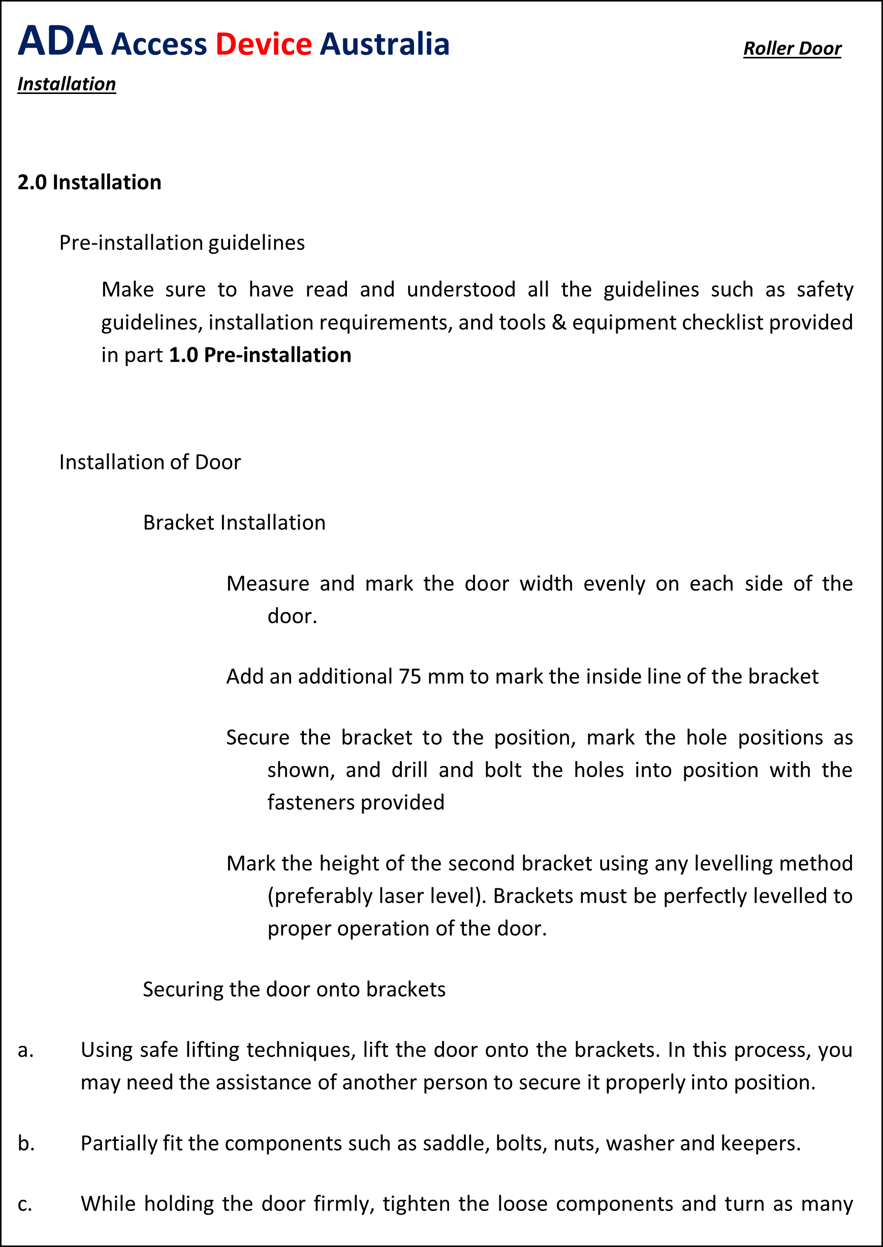
Shown below is a sample portion of a manufacturer’s specification for the installation of roller doors. Manufacturer’s specifications for window installation may appear similar to what is shown here.