
Structural roof systems and components
Timber and metal pre-fabricated trusses
Pre-fabricated trusses, commonly constructed using timber or metal (steel), are trusses manufactured and assembled offsite. These can be installed immediately upon delivery to the site. The main advantage of pre-fabricated trusses is that the quality of components is consistent and they are cut precisely according to specified dimensions. Another advantage is waste reduction since manual cutting is not required on the worksite.
The advantages and disadvantages of using either timber or metal (steel) prefabricated roof trusses are directly related to the intrinsic properties of the materials used. Prefabricated roof trusses are considered the safer alternative considering fire safety, the reason being that the outer layer of timber protects the core from being damaged. In other words, timber prefabricated roof trusses have a high chance of remaining stable even when exposed to fire. However, they are prone to warping when exposed to moisture and termite attack, which means protection measures must be applied.
Steel prefabricated roof trusses are generally robust against heavy wind loads and possess a higher strength-to-weight ratio, allowing them to take on heavy loads without buckling. Additionally, they are termite-resistant and can last for years with correct maintenance. However, they have poor performance against fire, which means that they must be applied with fire-protection methods to prevent collapse when exposed to fire.
Hand-Cut Timber
Hand-cut timber is a method that employs manual cutting, assembling, and installation of timber truss components on-site with the use of hand tools (e.g. mallet, hammer, chisel) and power equipment (e.g. circular saw, drills). This method produces more wastes on-site due to manual cutting procedures and (compared to pre-fabricated trusses) is more prone to errors and inconsistencies due to human limitation. However, one advantage of hand-cut timber is that actual measurements could be performed to verify the dimensions for the timber truss. Thus, this method is more flexible when it comes to adjustments.
- Below are components of a hand-cut timber roof:
- Rafters – provide support for roof coverings
- Purlins – provide additional support adding rigidity to the entire roof structure
- Battens – serves as an additional roof framework upon which other roof components (e.g. roof tiles, sheathing) are fixed
- Ridge board – a member found at the apex of the pitched roof which serves as the connection point between two opposing rafters
- Joists – horizontal members that run the length of opposing walls and serve as supports for ceiling and attic.
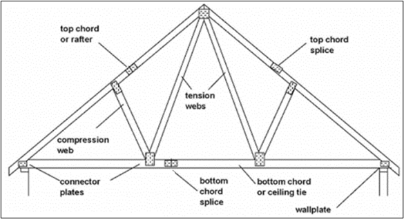
Truss Components
- The general truss components stated below serve different functions:
- Top Chord – mainly resists compression forces
- Bottom Chord – mainly resists tensile forces
- Web members or bracing – mainly resists shear forces subjected to the truss and could be resisting either tension or compression forces
- Wall Plate – component that provides proper bearing for rafters or truss ends against column or beam supports. Wall plates aid proper load distribution from the roof to the support and houses tie-down devices to prevent roofs from getting detached due to uplift caused by severe winds.
- Truss connectors – These components function to properly connect individual truss members at joints and aid the efficient transmission of loads from the truss to the support. Additionally, two separate members can act as one unit using truss connections. These are evident in member splices. The list below shows different types of connectors.
- For timber trusses:
- Gang-nail
- Split rings
- Toothed rings
- Shear plates
- Trip-L-Grip framing anchors
- For steel trusses:
- Bolt and gusset plate
- Cleat with fillet stiffener
- Welds
- For timber trusses:
Roof types
Box gable
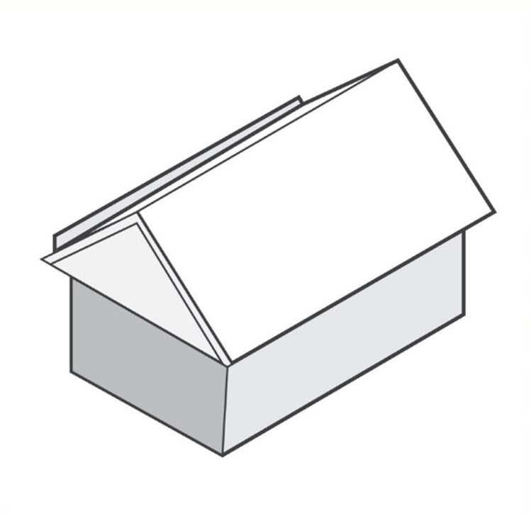
A gable roof is a type of roof that consists of two identical sloping roof sections that meet at the peak of the roof called roof ridge. A box gable is a type of gable roof such that the triangular section of the roof, or gable, is emphasised, as shown in the image on the following page. It is considered one of the most common roof types, especially in cold or temperate climates. It is particularly used to accommodate interior spaces for storage purposes (e.g. attic). One advantage of box gable roofs is that they allow water to flow easily off the roof, preventing any water ponding loads from happening. However, due to their form, they are susceptible to collapse in high wind and hurricane-prone areas, especially when no proper supports are provided. Below is an image of a box gable roof.
Dual pitch
Similar to a gable roof, a dual pitch roof employs two roof sections sloping against one another and meeting at peak to form a roof ridge. The roof ridge may not necessarily be at the centre. In this case, the dual pitch roof is considered asymmetrical. An asymmetrical dual pitch roof has two roof sections with different lengths and areas.
If the roof ridge is at the centre, it is considered symmetrical and is simply a gable roof.
The natural design of dual pitch roofs allows more flexibility in the application of insulation, which leads to better protection of the interior from extreme temperatures. However, due to their asymmetry, loads are not uniform throughout the roof, which leads to some foundations requiring larger designs to accommodate heavier loads.
Dutch gable and Dutch hip
As mentioned earlier, a gable roof has only two roof sections sloping against each other and meeting on the roof ridge. A hip roof has roof sections on all sides of the structure. Although hip roofs provide high protection against rain and high wind environment, they have a smaller attic space, which is one disadvantage of this type of roof. To address this, a gable may be applied and placed on top of the hip roof. The combination is called a Dutch gable and Dutch hip. It possesses characteristics of both a gable and hip roof and function well against rain and high wind. However, due to its large size, it transmits heavy loads to the supports. This means that supports must be designed to have a higher loadbearing capacity.
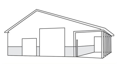
Gable end
In contrast to a box gable roof, a gable end is a type of gable roof in which the gable is not closed. In other words, the gable refers to the gable itself (i.e. triangular portion underneath the pitched roof) and entire wall beneath it, found at the end of the structure.

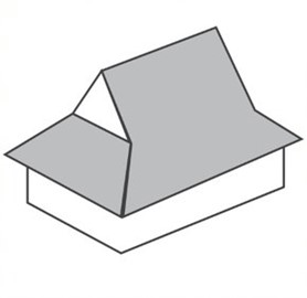
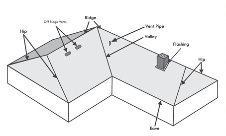
Hip and Valley
Hip and valley roof occurs when a non-rectangular building employs a hip roof system. Hip roof is a type of roof which consists of sloping roof sections on all sides of the building. The intersection between the roofs, as shown in the image below, is called the valley. Hip and valley roofs are more suitable in high wind environment than gable roofs since they possess high self-bracing capability.
The main disadvantage of hip and valley roofs is their susceptibility to leaks. This is due to their natural design wherein water may intrude at the seams that make up the valleys.
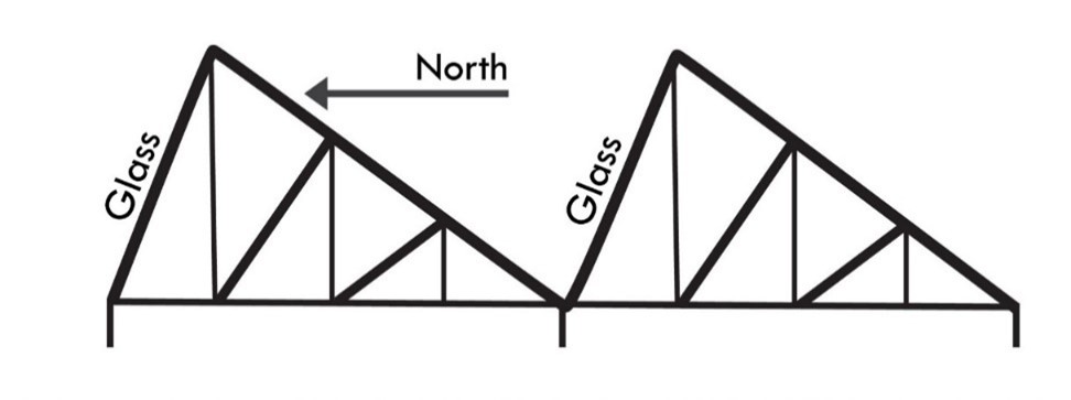
North light
North light is a series of dual pitch roofs with one roof section set at a steeper slope than the other. This is also known as sawtooth truss since the series of north light roofs resembles a sawtooth. This type of roof system is widely used in industrial buildings and allows natural light inside the buildings by employing glass in the steeper slope. A disadvantage that comes with the use of north light is possible overheating in the building.
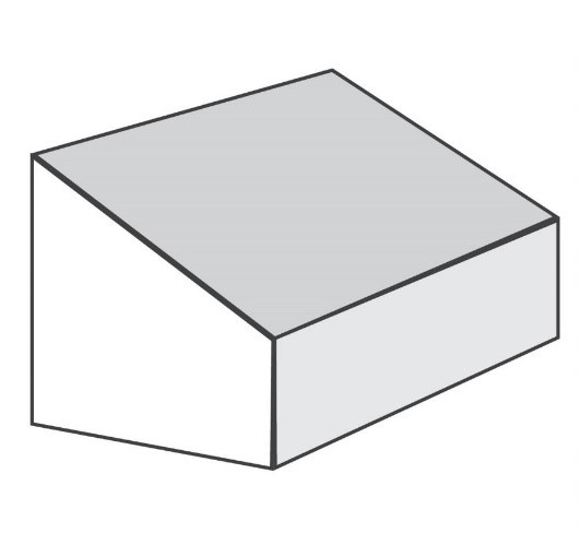
Skillion
A skillion roof is a roof type that consists of only a single large roof section sloping towards one side. Thus, unlike gable and hip roofs, skillion is a mono pitch roof. This type of roof is usually employed for aesthetic purposes, and high-ceiling applications in residential buildings create more interior space. In addition to that, this allows more natural light inside the building. From a structural perspective, it prevents additional loads from rainwater ponding. The main disadvantage of a skillion roof is it is generally weak against severe wind environments, so this type of roofing should be avoided in tornado prone areas.
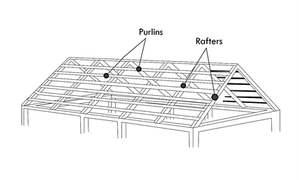
Rafter and Purlin
This type of roof system employs structural elements called rafters and purlins. Rafters are structural members that slope down from the roof ridge down to the eaves and supported by either beams or columns on one end. They function to support horizontal beams called purlins, as well as roof coverings and other roof elements. Purlins function to provide additional overall stiffness and stability to the roof, which prevents the buckling of rafters. Rafters and purlins may be made of different materials such as steel or timber. Refer to the image.
Performance requirements
In determining compliance with the NCC performance requirement, you must ensure that the installation or construction of the roof follows the compliance solutions set by the NCC. Refer to the table below for the compliance solutions relevant to structural roof systems.
|
Document |
Section/Part |
Description |
|
NCC Volume 1 |
B1.4(f)(iv) |
Deemed-to-Satisfy Provisions for structural resistance of materials and forms of construction for nailplated timber roof trusses: AS 1720.5 |
|
B1.4(j) |
Deemed-to-Satisfy Provisions for structural resistance of materials and forms of construction for roof construction (except in cyclonic areas) |
|
|
B1.5 |
Deemed-to-Satisfy Provisions for structural software used for the design of steel or timber trussed roof and floor systems and framed systems |
|
|
Specification C1.1 (3.2) & (3.5) |
Deemed-to-Satisfy Provisions for Type A Fire-Resisting Construction in relation to roofs |
|
|
NCC Volume 2 |
3.12.1.2 |
Acceptable construction practice for building fabric thermal insulation for roofs |
|
3.4.0.2 |
Provisions for structural software used for the design of steel or timber trussed roof and floor systems and framed systems |
|
|
3.4.3.0(b) |
Acceptable construction manuals for the design of nailplated timber roof trusses: AS 1720.5 |
|
|
3.4.4.2(a) (ii) & (iii) |
Acceptable construction practice for structural steel members used in supporting roof loads |
Structural roof refers to the framing and covering that resists structural loads such as wind, snow, and rain loads. In other words, it must be designed to withstand the uplift pressure caused by severe wind and avoid collapse from heavy snow loads and prevent water ingress caused by the rain.
As discussed in the previous section, there are two structural roofs: pre-fabricated roof trusses (timber and metal) and hand-cut roof members (timber). Pre-fabricated roof trusses are manufactured and assembled in truss prefabrication facilities and then transported to the site for installation. Hand-cut trusses comprise of hand-cut roof members involves manual cutting, assembling, and installing timber truss components on site using hand tools (e.g. mallet, hammer, chisel) and power equipment (e.g. circular saw, drills).
In planning the erection of the structural roof system, you must review the configuration of the type of roof system to be installed. This is to prepare the materials needed, as well as the equipment to be used for erection. After which, you must review the procedures for the erection of the roof trusses.
The procedures stated on the following page are based on the industry safety standard Erection of timber roof trusses, initiated by WorkCover NSW with collaborative efforts from various relevant Australian organisations. You can see the full document through the link in the Further Reading section at the end of this subchapter.
Note that the procedures below are general methods applicable to the erection of both types of structural roof (i.e. roof trusses and hand-cut roof members). For roof trusses, the fabricators usually provide the manufacturer specifications, which you should use to guide you in the erection of roof trusses.
During the implementation of the procedures, make sure that the work being done aligns with the specified procedures and check if the erection process complies with the construction standards, codes, and practices.
In the pre-erection stage, you should:
- Consult with relevant construction personnel to discuss matters and issues such as:
- Schedule of loading and unloading of trusses (for pre-fabricated trusses).
- Specifications for the crane required to lift the trusses. This includes the type of crane to be used, the access of crane, and safe positioning of the crane.
- Examine site conditions and the existence of services such as overhead power lines to assess risks.
- Be aware of the use of plant and equipment. This includes:
- Power supply, which should comply with the WorkCover code of practice Electrical practices for construction work. In the absence of such, an electrical generator may be used. Refer to the document for the provisions for electrical generator.
- Ladders and ramps. Ladders must comply with AS 1892.5 Portable ladders- selection, safe use, and care while ramps must comply with AS 4576. Additionally, they must be maintained in good condition, positioned on a stable flat surface, and set at a slope of approximately 4 to 1. Refer to the document for the complete provisions of ladders and ramps.
- Power tools. These should be in good condition. You must also make sure workers are competent in operating the tools and use personal protective equipment when using such.
- Cranes. In addition to risk assessment performed to promote safe access and use of cranes, you must ensure that crane operator holds a licence to operate the crane.
- Scaffolding and roof edge protection. Scaffolding must comply with AS/NZS 1576 ‘Scaffolding’, as well as AS/NZS 4576 ‘Guidelines for scaffolding.’ Meanwhile, roof edge protection should comply with AS/NZS 4994 ‘Temporary roof edge protection for housing and residential buildings.’
In the phase of roof truss erection, remember the following:
- Make sure that all areas are accessible and free of obstruction. Any opening or penetrations from which a person could fall must be protected by employing systems like guard rails, temporary studs, scaffolds, etc.
- If the lifting of roof trusses onto wall frame is to be done manually by workers, make sure that workers are capable of such tasks without factors such as size, weight, and positioning posing a risk to their health and safety. Otherwise, a crane must be used to perform this task.
- When the truss is to be lifted with a crane, it should be laid flat or suitably supported.
- Whether cranes or manual lifting is used in the erection of first and second standard trusses, at least two people must be stationed at opposite ends to fix the truss on top of the wall plate firmly. The two trusses must be temporarily braced. For manual lifting, a third person may be stationed in the middle to assist the placement of the truss. After which, subsequent trusses may be installed using the same process or by following the manufacturer’s specifications.
- Fall protection systems should be maintained to safeguard workers who are working between trusses. The bottom chord of trusses is recommended for use as a safe work platform if trusses are adequately braced and free of defects (e.g. cracks, splits) that could compromise structural integrity and pose a risk to the workers.
- If the apex or high bracing points of the truss cannot be reached while standing on the bottom chord, temporary waling plates should be used provided they fit and comply with the manufacturer’s specifications. When no longer required, these should be removed.
Before going deeper into the planning, implementation and checking of roofing components, you must know what these components are. Key roof components and their function are listed below.
- Roof sarking – This is a protective layer installed under the roof. Sarking protects the interior of the structure from roof water intrusion and dust and functions to improve the thermal performance of the structure. Additionally, it reduces the risk of unwanted condensation and possesses a level of fire resistance, which helps resist bushfire ember attacks.
- Skylights – These are also called rooflights. Essentially, they are daylight-transmitting components that form part of the roof or installed on the roof surface. Skylights provide benefits related to comfort and energy efficiency and have different types including:
- Sloped roof windows
- Unit skylights
- Tubular Skylights
- Roof ventilators – These are components that allow air circulation and regulate indoor temperature. Additionally, this improves the roof's life since it protects the structure from damage caused by rot.
Lastly, service penetrations refer to the creation of opening or holes on roofs, ceilings or walls to accommodate components such as pipe systems, switches and sockets and the like for plumbing, mechanical and electrical services.
Roof cladding
Roof cladding is a component that makes up the external surface of the roof. While providing visual appeal for the structure, roof cladding protects the roof against factors such as weather, fire, wind, temperature changes, and sound, and aids in the flow of rainwater. Below are common types of roof cladding.
Shakes and Shingles
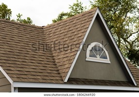
Shingles are roof cladding components that consist of typically flat rectangular overlapping components and made of different materials such as wood, asphalt, metal, and slate (stone). Shakes are roof cladding components typically made of wood and possess features like wood shingles.
The difference between the two is in their appearance and durability. Due to the manufacturing method, shakes have a slightly rougher texture compared to shingles. Shakes are considered more durable than shingles since they are slightly thicker. When it comes to installation, shingles can be laid flatly on the roof, while shakes, due to manufacturing irregularities, cannot be laid completely flat.
Overall, shakes and shingles provide great aesthetic appeal to roofs. They possess high insulating properties. However, they are susceptible to damage due to high wind. Compared with other roof cladding components, they have shorter life spans since they are more susceptible to damage from heat.
Concrete, Clay and Metal Tiles
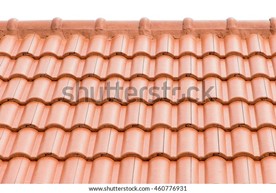
Roof tiles have the same function as shingles, the main difference being that roof tiles are manufactured in various forms other than a flat profile. They may be curved, s-shaped, or semi-cylindrical interlocking units made of concrete, clay, or metal. Roof tiles are heavy, durable, and highly fire-resistant, making them an excellent choice for roofing.
Concrete, clay, and metal tiles all possess high aesthetic function. Due to their natural properties, clay tiles are durable against damaging weather conditions and are highly fire-resistant. However, they are very brittle, which makes them susceptible to cracks.
The density of concrete tiles gives them high durability against high wind loads and weather conditions. Additionally, they are also fire-resistant. However, due to their weight, the roof structure and its supports must be designed to have greater load bearing capacity.
Unlike concrete tiles, metal tiles are generally light and possess high durability when exposed to high winds since they have a high strength-to-weight ratio. However, metal tiles are high heat conductors, which means they tend to allow heat from the environment to the inside of the structure more than concrete and clay tiles. As metals are susceptible to corrosion, preventative measures may be needed.
Short and Long Run, Various Profile and Metal Sheeting

Metal sheeting is a roofing component composed of galvanised steel sheets with corrugated patterns or profiles. Components are installed overlapped laterally and vertically to provide a barrier against water ingress. The main advantage of using metal sheeting is its lightweight property while providing sufficient strength to resist high-wind forces.
In many cases, long run roof sheeting extends from the ridgeline to the guttering, minimising breaks and overlaps. This reduces the chances of trapped moisture in overlapped areas and reduces the risk of leaks. Additionally, long run roof sheeting provides a visually pleasing streamlined look.
On the other hand, short run roof may appear less aesthetically pleasing due to more breaks and overlaps necessary to secure them into place. However, the breaks and overlaps provide more stability against high wind loads. This prevents the sheeting from being detached from the roof due to extreme wind.
There are various roof sheet profiles available, which serve different functions and aesthetic appeal. Some examples include:
- Corrugated roofing – The folds or corrugations employed gives the cladding a high strength to resist wind loads over large spans and prevents sagging.
- Polycarbonate roofing – Due to its natural properties, polycarbonate roofing function well against harsh temperatures and degradation caused by weather.
- Plastic roofing – Composed of plastics such as polypropylene, polyethylene, etc., plastic roofing sheets are generally lightweight, as well as anti-corrosive and waterproof. They can be used for specific light structural construction purposes.
A properly installed metal sheeting provides weather tightness and high thermal performance and structural capability to withstand wind, rain, and snow loads. However, rusting is inevitable, especially in areas near the coast or where rainfall is acidic. Corrosion prevention measures must be applied to minimise this.
In planning the installation of roof cladding, ensure that you have reviewed the configuration of the roof cladding for the building project. This allows you to prepare the necessary materials and equipment needed and the procedures to carry out the work. After that, ensure that actual installation procedures align with the procedures specified in the plan.
Compliance with building standards, codes and manufacturer specifications
In planning the installation of roof components such as roof sarking, skylights, and ventilators, you must review the project plans and specifications to know the following:
- Types to be used – refers to the material or configuration of the roof components
- Roof sarking – Sarking boards, polystyrene, etc.
- Skylights – sloped roof windows, unit skylights, tubular skylights, etc.
- Roof ventilators – ridge vents, box vents, turbines, etc.
- Location – refers to where precisely the roof components are to be installed
After considering these items, you must then review the relevant NCC requirements and the corresponding Australian Standards. The relevant NCC requirements and corresponding Australian Standards will be discussed later in this section.
To plan the installation of service penetrations, you must first identify the services to be installed on the roof and their locations. In other words, you must review the project plans and specifications to know what service components are to be installed through the penetrations (e.g. pipes, wires or cables, sockets and switches) and then examine how they are laid out or positioned in the building project. Finally, you must review the relevant NCC requirements for service penetrations, which is mainly covered in NCC Volume 1 Specification C3.15 Penetration of walls, floors and ceilings by services.
The table below shows the document, the part or section, and the corresponding description of the relevant NCC provisions for roof sarking and cladding, skylights, roof ventilators and service penetrations to ensure compliance with standards and codes. You can refer to this table to guide you during the installation of roof components. Additionally, this table can be used to check the compliance of the roof components and the installation process.
|
Document |
Part/Section |
Description |
|
NCC Volume 1 |
B1.2c (iv) & (v) |
Deemed-to-Satisfy Provisions for determination of individual actions in relation to metal roof cladding |
|
Specification B1.2 (2) |
Deemed-to-Satisfy Provisions for design of buildings in cyclonic areas in relation to metal roof cladding |
|
|
Specification C3.15 |
Deemed-to-Satisfy Provisions for penetration of walls, floors and ceilings by services |
|
|
|
FV1.1 |
Verification methods for weatherproofing in relation to cladding |
|
Specification J1.2 (2)(a) |
Deemed-to-Satisfy Provisions for the thermal conductivity of roof and wall cladding used in construction |
|
|
J1.4 |
Deemed-to-Satisfy Provisions for roof lights in relation to energy efficiency |
|
|
J3.3 |
Deemed-to-Satisfy Provisions for roof lights in relation to building fabric |
|
|
Schedule 7 (2.6) |
Design scenario for vertical fire spread involving external cladding or external openings (Fire Safety Verification) |
|
|
F1.6 |
Deemed-to-Satisfy Provisions for sarking-type material used for weatherproofing of roof and walls |
|
|
Specification J1.2 (2)(d) |
Deemed-to-Satisfy Provisions for roof vent and roof ventilators in relation to energy efficiency |
|
|
NCC Volume 2 |
V2.2.1 |
Verification methods for weatherproofing in relation to cladding |
|
V2.6.2.2(c)(viii) |
Verification methods for verification using a reference building in relation to roof cladding |
|
|
3.5.1.0 |
Acceptable Construction Manuals (application part) for sheet roofing |
|
|
3.5.1.1 to 3.5.1.8 |
Acceptable Construction Practice:
(continued from previous page)
|
|
|
3.5.2.0 |
Acceptable Construction Manuals (application part) for roof tiles and shingles |
|
|
3.5.2.1 to 3.5.2.6 |
Acceptable Construction Practice:
|
|
|
NCC Volume 2 |
3.7.1.1 (f) |
Acceptable Construction Practice for sarking-type materials in relation to fire safety |
|
3.7.1.2 |
Acceptable Construction Practice for sarking-type materials in relation to the corresponding flammability index |
|
|
3.12.1.2(b) |
Acceptable Construction Practice for roof vents and roof ventilators in relation to energy efficiency |
|
|
3.12.1.3(b) |
Acceptable Construction Practice for roof lights in relation to energy efficiency |
|
|
3.6.0(b)(iv) |
Acceptable Construction Manuals for glazing in relation to skylights, roof lights and windows in other than the vertical plane |
|
|
3.6.1(g)(iv) |
Acceptable Construction Practice for glazing assemblies in relation to skylights, roof lights and windows in other than the vertical plane |
|
|
|
3.7.2.8 |
Acceptable Construction Practice for rooflights, skylights or the like in relation to fire separation of external walls |
|
3.7.3.4 |
Acceptable Construction Practice for rooflights, skylights or the like in relation to fire protection of separating walls and floors |
The table below shows the Australian Standards relevant to the roof components mentioned. The NCC references these Australian Standards.
|
Roof Components |
Australian Standards |
Descriptions |
|
Roof Sarking |
AS/NZS 4200.1:2017 Pliable building membranes and underlays, Part 1: Materials |
Provides the specifications for the materials to be used as pliable building membranes when used as insulation materials and control functions for water, thermal vapour or air control |
|
Roof Sarking (cont.) |
AS/NZS 4200.2:2017 Pliable building membranes and underlays, Part 2: Installation |
Provides the specifications for the installation of pliable building membrane intended to be used as sarking or thermal insulation, or a vapour barrier |
|
Skylights |
AS 4285:2019 Rooflights |
Provides the specifications for the manufacture and testing of rooflights. Additionally, it provides the requirements for materials, maintenance and other considerations for rooflights |
|
Roof Ventilators |
AS 1668.2 - 2012 The use of ventilation and airconditioning in buildings - Mechanical ventilation in buildings |
Provides the specifications for the application of mechanical air-handling systems that ventilate buildings and car parks |
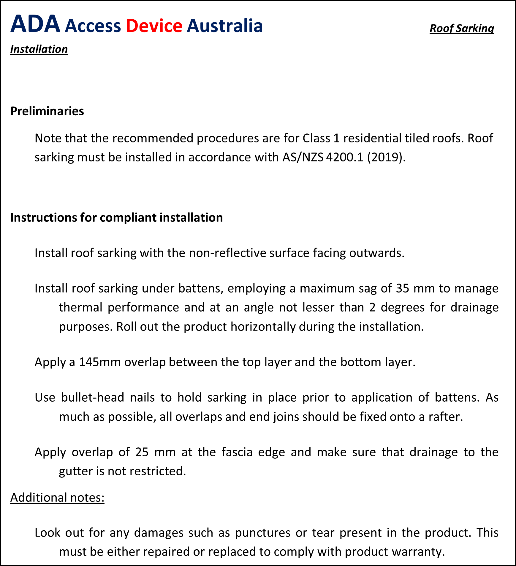
In the planning and implementation of roof components, the manufacturer’s specifications may be used. Manufacturer’s specifications contain details such as technical product specification, tools and processes used in the manufacturing process, health and safety provisions, limitations of the product, and step by step installation procedures. To comply, one must carefully read and implement the procedures stated. In doing so, you must focus on questionable areas of the specification and cross-examine them with the provisions in the NCC or consult with industry professionals.
Shown below is a sample portion of a manufacturer’s specification for the installation of roof sarking. The manufacturer’s specifications for installing other components may appear more or less similar to what is shown.
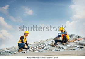
Roof systems and components must be installed carefully and correctly. You have to manage the processes properly to ensure the quality of the roof finish as this is responsible for the prevention of potential damage from environmental factors such as water leakage and is a contributing factor to overall building aesthetics. In doing so, you must oversee the whole process and refer to the general guidelines discussed in this section.
Whether they are shakes or shingles, tiles, or metal sheeting, the general guidelines stated below may be followed to ensure roof system quality finish. However, in all cases, the manufacturer's specifications must also be considered since they may contain specific details not mentioned in the guidelines below.
- Ensure that roof rafters or trusses are clean and free of splinters, old nails, or any obstruction that may cause damage to the overlying membrane.
- Roll out preferred membrane or roof sarking horizontally (from left to right). Start laying the sarking at the bottom portion of the roof.
- Once the length is rolled out, secure the left end against the rafter or truss with fasteners or nails. Drive the nails adequately in a manner that does not damage the sarking.
- Before securing the opposite end with nails, give it a gentle pull, but not too hard. You should allow a small degree of sagging of the sarking between roof trusses or rafters. This is for the purpose of directing water that might have leaked in through the roof tiles or sheets.
- Install and space battens according to manufacturer’s specifications. They should be secured with galvanised nails that penetrate adequately through the truss or rafter underneath. Make sure that the battens are parallel to each other.
- Lay and secure the rest of the sarking towards the ridge. After this, establish the rest of the battens. Make sure you apply sarking overlap and batten spacing in accordance with the manufacturer’s specifications.
- The roof can now be installed with roof cladding such as shakes or shingles, tiles, or metal sheets. Refer to the details below before continuing to item number 8.
Roof Tiles
- You must follow the tile nailing procedure based on the manufacturer’s specifications. The nails should be hammered adequately through the battens but not too deep that it reaches the sarking.
- Make sure that tiles overlap adequately and are hooked securely on top of the battens. Set the bottom tile with a small overhang to direct flowing water towards the gutter and prevent it from dripping down the fascia.
- Apply a small overhang at the verges and make sure that the high profile of the tile is used as the overhang edge. This is for the purpose of avoiding or minimising water dripping down the building wall. If the roofing to be used is a flat profiled tile, make sure to stagger every course, so that vertical joints do not sit directly on top of each other.
- Make sure to check everything according to manufacturer’s specifications.
Roof Shingles
- Apply nailing procedure, overlaps, and overhangs in accordance with manufacturer’s specification.
- Keep in mind to stagger every course so that vertical joints do not sit directly on top of each other.
- Drip edge may be used on the sides to prevent fascia damage and avoid water dripping along the walls.
Metal sheeting
- Apply nailing procedure, overlaps, and overhangs in accordance with manufacturer’s specification.
- Since metal sheets are high heat conductors, additional thermal insulation may be added. Refer to the manufacturer’s specifications for the details.
- Apply metal sheeting wherein necessary (e.g. head wall flashing, side wall flashing, roof apex capping)
8. When roofing is completely installed, run a quality check or inspection. Make sure that all components are secured in place, and penetrations have been sealed well.
Watch the videos below to see the installation process of roof tiles
Watch the videos below to see the installation process of roof shingles
Watch the videos below to see the installation process of colorbond