
A construction plan is a detailed document, or set of documents, that outlines the details of a construction project. Construction plans generally provide the following information:
 |
 |
 |
| project schedule | Methodologies | Preleminary drawings and photographs that illustrate the design |
It is important to select all the relevant information from construction plans to prepare to sketch or create a drawing. This will ensure that accurate information is transferred to the drawings and sketches.
Key features of a construction plan
Key features refer to drawing elements typically included in construction plans. You need to know and understand them since each key feature functions differently in terms of the information it provides.
- Site plan
- Floor plan
- Sub-floor plan
- Elevations
- Sections
- Details
Key features of a construction plan include the following:
Site plan
A site plan is a drawing that provides an overview of the entire property. It shows all site elements for consideration in constructing a building and gives an idea of the entire scope of work involved in the project. Additionally, a site plan is usually drawn at a smaller scale to ensure that all the required information is placed in the drawing sheet. An example is shown here.
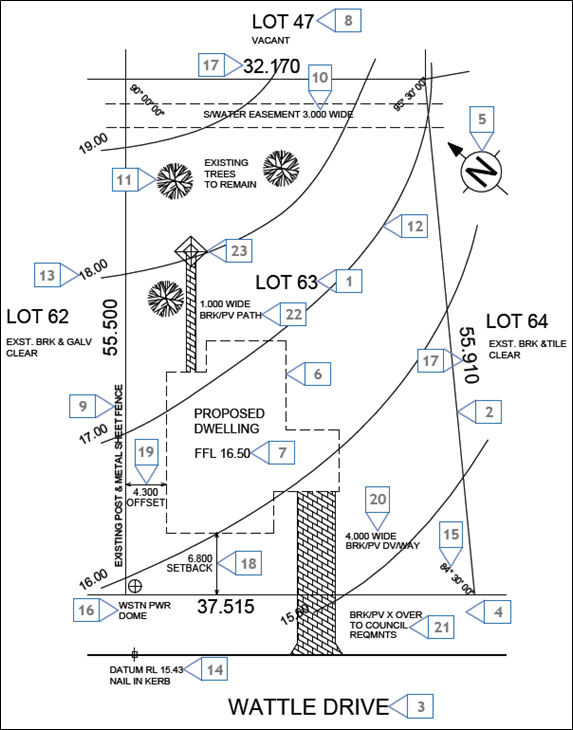
A site plan can be used for purposes such as identifying adjacent roads, identifying the location of the project site, determining any structures to be retained or demolished, and determining the building layout and orientation.
Below are the key features of a site plan, according to the Department of Training and Workforce Development (2016)2. Note that the numbers below correspond with the labels in the sample site plan.
- Block identification – refers to the block number of the land
- Boundary – refers to an imaginary line that defines the block of land, wherein corners marked with wooden pegs
- Road identification – refers to the names of roads adjacent to the property
- Verge – refers to the portion of land between the block and the road, which usually has services running beneath it. Since this is not part of the block, it must not be built on or modified in any way.
- North point – shows where the north direction is, the orientation of the building and the entire site.
- Proposed building – shows the outline and location of the building to be constructed
- Finished floor level – refers to the finished floor level of the building to be constructed
- Adjacent properties – refers to the lot numbers of adjacent blocks of land
- Existing fences – refers to fences already existing on the block
- Easement – refers to a portion of land wherein another party exercises a legal right (e.g. council has the right to use a section of land solely for stormwater lines)
- Existing trees – refers to the trees that exist in the site. They are specified as site elements to be retained in the sample site plan.
- Contour lines – refers to imaginary lines which describe the profile of the land. In the site map sample shown, the block is sloping down from north to south.
- Contour level – refers to the 'reduced level' of the contour. For example, in the site map sample shown, the contour lines are in one-metre intervals.
- Datum – refers to a reference point on or near the block from which all site elevations are measured.
- Angle of boundary intersection – refers to the angle at which the boundaries meet.
- Location of power connection – shows where electrical connections will be made.
- Boundary length – refers to the length of the boundaries of the block.
- Setback – refers to the distance from the front boundary to the nearest part of the building.
- Offset – refers to the distance from the side boundaries to the nearest part of the building.
- Driveway – refers to the location and width of the driveway.
- Crossover – refers to the continuation of the driveway across the verge.
- Path – refers to any paving works included in the contract.
- Clothes hoist – refers to the positioning of the clothes hoist in the site.
Floor plan
A floor plan is a graphical representation of a building section's top view. It shows the arrangement of elements such as walls, columns, doors, and windows and defines the limits of the building's different spaces. The image below shows a floor plan of a Banksia House, sourced from Your Home website[3].
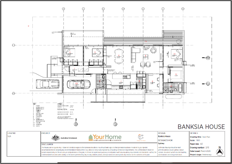
Access 02 Technical Drawings Banksia_Sydney here.
You can refer to the floor plan when identifying the different furniture and appliances for the building. Additionally, you can use it to determine the function of the different building spaces and their dimensions. Other types of information that can be acquired include, but are not limited to, the following:
- Location of appliances
- Layout of walls
- Width of doors and windows
- Width of stairs
- Arrangement of furniture
Sub-floor plan
In some cases, especially in floor framing construction, a sub-floor is employed. A sub-floor includes all components that lie underneath the top of the floor, responsible for supporting the flooring and the structure above it.
A sub-floor plan contains all information about the subfloor and its components. Refer to the image below of a sample sub-floor plan. [4]
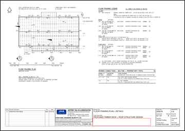
Access Sample A-04 here.
Elevations and sections
Elevations show the vertical projection of the building as seen on the outside. In other words, it shows how the building façade looks like at the front (front view), back (rear view), and sides (right side and left side view). This allows one to analyse the relationships of components found only on the building exterior (e.g. wall finish). Other details which can be obtained from elevation views include the floor-to-ceiling height and roof height. The images below show examples of elevations. [5]
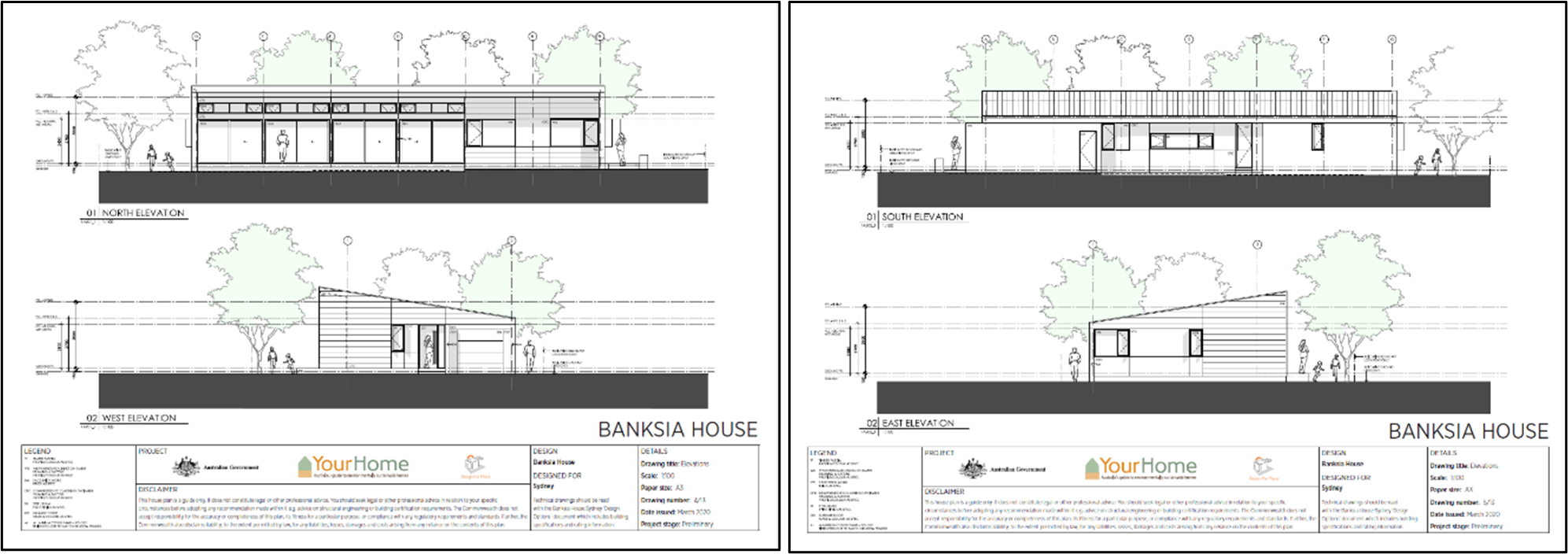
Access 04 Technical Drawings Banksia_Sydney and 05 Technical Drawings Banksia_Sydney here.
On the other hand, sections show how a structure looks from an imaginary vertical plane that cuts through it. This imaginary cutting plane allows one to see through the structure's interior, which is otherwise concealed by the exterior walls.
Since section views allow one to look at the building interior, one can analyse the relationships among and integration of building interior elements. Additionally, section views will enable the identification of any variations in a floor level. Other details which can be obtained from section views include but are not limited to the following:
- Floor-to-ceiling height
- Dimensions of doors, windows, and other openings
- Dimensions of fixtures, furniture, and equipment
The images here show section examples. [6]
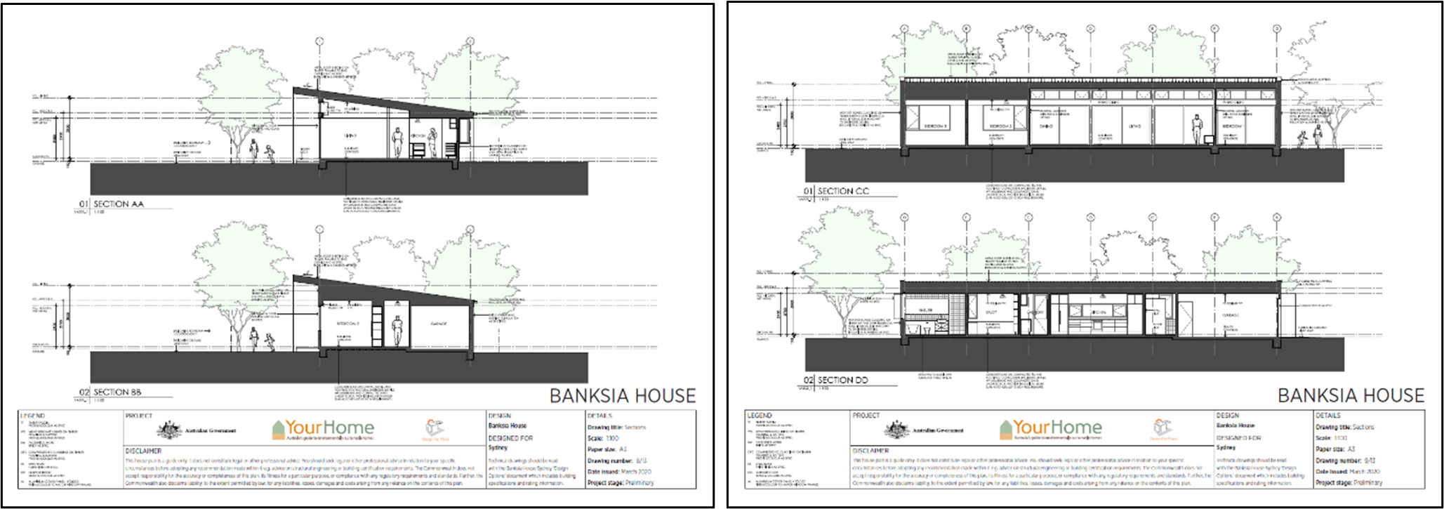
Access 08 Technical Drawings Banksia_Sydney and 09 Technical Drawings Banksia_Sydney here.
Details
Generally, plans are drawn in the appropriate scale for a drawing sheet to cover the necessary information. However, there are instances when one needs to look deeper into a particular part or component of a building to examine it. This is when detail drawings come into play.
Details are drawings that provide large scale views of parts or components of a building, used to examine and analyse intricate details and any complex configuration. Additionally, detail drawings are used to see and understand exactly how a job is to be done.
For example, you intend to know the width and thickness of the stair tread and the measurement of the stair rise. To identify them, you need to look into the stair detail drawings. An example of a stair detail drawing is shown here. [7]

Types of construction plans
In a building project, different types of plans serve different purposes and contain specific technical details regarding the particular construction areas. They can be used to visualise the finished project.
Refer to the table showing a summary of the different construction plans and their corresponding descriptions and information provided.
|
Description |
Use |
|
|
Presentation drawings |
Presentation drawings include tones or hatches to represent different materials. They are diagrams and not intended to appear realistic. Basic presentation drawings typically include people, vehicles, and trees. |
Presentation drawings are used to explain a scheme and to highlight its features. They are used to describe the design and are generally shown to clients during the design process. |
|
Isometric drawings |
An isometric drawing is a three-dimensional (3D) drawing set out using 30-degree angles. In an isometric drawing, the foreshortening of the axes is equal. Therefore, the final image produced is not distorted. |
Isometric drawings are used to provide a 3D representation of an object, building, or design on a 2D surface. |
|
Orthographic drawings |
Orthographic is two-dimensional (2D) drawings. In each of these drawings, the object (e.g. house) is viewed along parallel lines that are perpendicular to the plane of the drawing (e.g. top view, front view, and side view). |
Orthographic drawings are used to show an object from every angle to help the builders/contractors plan the construction. |
|
Perspective drawings |
Perspective drawings approximate a flat surface of an object (e.g. a house or a building) as the eye perceives it. |
Perspective drawings depict spatial depth or perspective and accurately depict a 3D object onto a 2D plane. |
While the types of construction plans consist of the key features discussed in the previous section, they are also composed of the different types of construction plan drawings. Refer to the table below for the types of construction plan drawings and their respective description.
|
Description |
Use |
|
|
Presentation drawings |
Presentation drawings include tones or hatches to represent different materials. They are diagrams and not intended to appear realistic. Basic presentation drawings typically include people, vehicles, and trees. |
Presentation drawings are used to explain a scheme and to highlight its features. They are used to describe the design and are generally shown to clients during the design process. |
|
Isometric drawings |
An isometric drawing is a three-dimensional (3D) drawing set out using 30-degree angles. In an isometric drawing, the foreshortening of the axes is equal. Therefore, the final image produced is not distorted. |
Isometric drawings are used to provide a 3D representation of an object, building, or design on a 2D surface. |
|
Orthographic drawings |
Orthographic is two-dimensional (2D) drawings. In each of these drawings, the object (e.g. house) is viewed along parallel lines that are perpendicular to the plane of the drawing (e.g. top view, front view, and side view). |
Orthographic drawings are used to show an object from every angle to help the builders/contractors plan the construction. |
|
Perspective drawings |
Perspective drawings approximate a flat surface of an object (e.g. a house or a building) as the eye perceives it. |
Perspective drawings depict spatial depth or perspective and accurately depict a 3D object onto a 2D plane. |
Identify and select relevant information
As construction personnel tasked with communicating ideas to clients, you need to correctly identify and select relevant information from construction plans that need to be captured and relayed to clients and other parties.
You learned about the key features of construction plans and the different types of construction plans in the previous section. Use that knowledge to identify and select relevant information.
In identifying and selecting relevant information from construction plans required for sketching or drawing, there are three basic steps:
- Identify and refer to the correct type of plan.
- Read the details of the plan at hand.
- Select the specific information that is required.
To illustrate this further, refer to the different sample situations below.
Situation # 1
The client intends to see all the spaces or rooms in the building, including their corresponding positions and dimensions.
What you can do:
Identify the correct type of plan that provides information regarding building spaces and their corresponding positions and dimensions, which is the architectural plan. Then, refer to the details in the architectural plan and select the floor plan. By selecting the floor plan, you can now see and obtain the necessary information you need regarding the building spaces and their positions and dimensions.
Situation # 2
The client intends to visualise how the building looks like at the front, sides, and rear.
What you can do:
Identify the correct type of plan, which in this case, is the architectural plan. Next, refer to the details in the architectural plan and select the elevations view. Now, through the elevations view, you can see the building's front, sides, and rear view.
Situation # 3
The client intends to visualise the position of the building with respect to other structures or elements that can be found in the property or block.
What you can do:
Identify the correct type of plan, which in this case, is the site plan. Refer to the details in the site plan and select the drawings which show the outline of the perimeter of the building. Based on that outline, you can see the building position and orientation and the location of other site elements such as trees, fences, shrubs, etc.

It is essential to confirm that the construction plan complies with build and construction regulations, standards, and codes. While the following section defines the meaning of regulation, codes, and standards, the following sentence discusses a brief overview of the difference between them. Regulations set out the specific requirements of a particular act, while codes of practice and standards provide practical information on meeting these requirements.
Failure to confirm compliance before the construction phase can cause delays to the project, safety issues, and possible fines. There is also the possibility of rejection of the construction plans by the building authorities. This section will discuss the different building and construction regulations, standards, and codes you need to adhere to.
State and territory legislation
It is essential to understand the difference between acts and regulations. Their definitions are:
|
Acts |
Regulations |
|
An act is legislation passed by the Parliament and amended only by another act. It sets out broad legal and policy principles. |
A regulation (together with rules, codes, etc.) is an example of a 'subsidiary legislation.' It contains guidelines that tell you how to apply the provisions of an act. |
Depending on the state or territory you are in and the classification of your building, there are different acts and regulations that you must follow during the construction phase.
You can see some of the acts and regulations in each state and territory relevant to different building classifications in the table.
|
Act (Class 2, 3, and 9) |
Regulations (Class 2, 3, and 9) |
Act (Class 5, 6, 7, and 8) |
Regulations (Class 5, 6, 7, and 8) |
|
|
Australian Capital Territory |
||||
|
New South Wales |
||||
|
Northern Territory |
||||
|
Queensland |
||||
|
South Australia |
||||
|
Tasmania |
||||
|
Victoria |
Residential Tenancies (Rooming House Standards) Regulations 2012 |
|||
|
Western Australia |
Environmental requirements
Construction methods that neglect to control pollution can cause lasting and permanent damage to land, groundwater, and the surrounding environment. The environmental risk is greater in construction projects near creeks, waterways, and coastal areas. In addition, construction in metropolitan and built-up areas can lead to air and noise pollution in surrounding communities and neighbourhoods. To address these, building and construction projects must follow the environmental requirements to address construction-related issues and problems.
Refer to the table below for the environmental acts for each state and territory.
Each state and territory is governed and regulated by an environmental regulatory authority with enforcement powers to impose sanctions, issue fines, and cancel licences. The Environment Protection Authority is the regulatory authority in every state and territory except for Queensland, where it is the Department of Environment and Heritage Protection and Western Australia, where it is the Environmental Protection Authority and the Department of Water and Environmental Regulation.
Workplace safety
The building and construction industry is associated with high-risk work, hazards, and injuries. Therefore it is essential for contractors, builders, and all personnel on construction sites to adhere to workplace health and safety (WHS) requirements and legislation.
WHS covers regulations about on-site and workplace health, safety, and welfare. It covers all workers, including:
- employees
- contractors and subcontractors
- outworkers
- apprentices and trainees
- work experience students and volunteers
- volunteers
- employers who perform work
The WHS legislation for each state and territory and its corresponding regulator are shown here.
|
WHS Legislation |
WHS Regulator |
|
|
Australian Capital Territory |
||
|
New South Wales |
||
|
Northern Territory |
Work Health and Safety (National Uniform Legislation) Act 2011 |
|
|
Queensland |
||
|
South Australia |
||
|
Tasmania |
||
|
Victoria |
||
|
Western Australia |
Each state and territory also has its own Construction Code of Practice. A Code of Practice provides practical guidance to principal contractors and other persons conducting building work on meeting the WHS legislation and requirements. The following table shows the relevant codes for each state and territory with links to their websites.
NOTE: At the time of writing, South Australia, Victoria, and Western Australia do not have a dedicated Code of Practice for Construction Work. In which case, you must refer instead to the code of practice relevant to building work, e.g. the state or territory's code of practice for demolition, excavation, etc.
The National Construction Code
The Australian Building Codes Board (ABCB) produced and maintained by the National Construction Code (NCC) on behalf of the Commonwealth, State and Territory Governments. It provides the minimum mandatory requirements for safety, health, amenity, and sustainability for building works of both new and existing buildings throughout Australia.
Building work is defined broadly in the NCC and includes the following activities:
- Construction
- Alteration
- Extension
- Restoration
- Repair
- Demolition
- Dismantling
- Installation of fittings such as heating, lighting, sanitation, ventilation, power supply, drainage, etc.
- Any operation to prepare for or finish the activities mentioned above, including site clearance, laying of foundations, provision of access works, etc.
The NCC incorporates all building work requirements into a single code containing three volumes. The Building Code of Australia (BCA) is divided into Volumes One and Two, and the Plumbing Code of Australia (PCA) is Volume Three.
The Volumes of the NCC covers different building classifications:
|
NCC 2019 Volume One Amendment 1, CC BY-ND 4.0 © Commonwealth of Australia and the States and Territories 2020, published by the Australian Building Codes Board. Image cropped from original document.
|
NCC 2019 Volume Two Amendment 1, CC BY-ND 4.0 © Commonwealth of Australia and the States and Territories 2020, published by the Australian Building Codes Board. Image cropped from original document.
|
NCC 2019 Volume Three Amendment 1, CC BY-ND 4.0 © Commonwealth of Australia and the States and Territories 2020, published by the Australian Building Codes Board. Image cropped from original document.
|
|
Volume One of the NCC covers the technical design and construction requirements for all Class 2 to Class 9 buildings (multi-residential, commercial, industrial, and public assembly buildings) and all their associated structures.
|
Volume Two of the NCC covers the technical design and construction requirements for certain residential and non-habitable buildings and structures, specifically Class 1 and Class 10 buildings. Volume 2 of the NCC contains further information on the performance requirements that builders are expected to adhere to during the building process.
|
Volume Three of the NCC (Plumbing Code of Australia) pertains to plumbing and drainage system of all building classifications.
|
All aspects of the building, including structural details, must comply with the NCC requirements, which are:
General Requirements
Also known as Governing Requirements, the General Requirements contain the rules and instructions for using and complying with the NCC. In addition, they serve as a guide in understanding how the technical requirements should be applied to any particular situation.
The Governing Requirements are outlined in Section A of Volume One, Section 1 of Volume Two and Section A of Volume Three. These provide the rules and instructions for using and complying with the NCC, including the following:
- Interpretation of the NCC
- Referenced documents such as Australian Standards
- Acceptance of design and construction (such as evidence of suitability and other related documentation)
- Classification of buildings
Performance Requirements
These are requirements that state the minimum level of performance for buildings and plumbing and drainage installations. These requirements can be achieved through compliance options, such as performance solutions, deemed-to-satisfy solutions, or a combination of both.
The NCC classifies buildings based on the nature, use and arrangement of buildings. These are defined as follows:
- The nature of a building refers to the inherent characteristics of a building.
- The use of a building refers to the purpose for which it was designed, constructed or adapted.
- The arrangement of a building refers to how its parts and elements are positioned.
The NCC legally applies in all the respective state and territory legislation. However, any NCC provision may be overridden by or subject to state or territory legislation. As such, they must always be read together.
The preparation of building drawings and sketches is part of the planning process. As the NCC sets out the technical provisions for the design, construction, and performance of buildings and plumbing and drainage systems, these requirements must be reflected in the building drawing and sketches (during the planning stage). That is, the drawings and sketches at this stage must show that the design, materials, or construction meets the relevant Performance Requirement or Deemed-to-Satisfy (DTS) Provision.
Building and construction standards
Complying with standards is one way to achieve compliance with government minimum requirements set out in the NCC. In addition, standards serve as concrete examples of best practices that can then be used to model what needs to be done in a building and construction project. They serve as thresholds that the project must meet to achieve safety and achieve sustainability and proper functionality. These standards will be used to assess the completed building as well, so referring to them during the construction phase means greater chances of passing these assessments.
As construction personnel tasked with preparing simple building sketches and drawings, you need to know and understand the following standards:
AS 1100.101-1992 – Technical drawing, Part 101: General principles
This standard covers the basic principles of technical drawing practices. For example, it covers the basic use of abbreviations, materials, sizes, and layout of drawing sheets, requirements for distinct uniform letters, numerals, and symbols, recommended scales, and their applications, etc. Additionally, it provides the standards for technical drawings, diagrams, charts, and tables and the specifications to use for scaling, ratios, technical drawing principles, and conventions to assist architects, engineers, and other building and construction professionals in creating quality sketches and drawings.
AS ISO 128.20-2005 – Technical drawings - General principles of presentation, Part 20: Basic conventions for lines
This standard contains general rules for the presentation of lines in all kinds of technical product documentation, including preparation of lines by CAD systems, basic conventions and applications for leader lines and reference lines, lines on construction drawings, etc.
Confirm compliance of construction plan information
Using the knowledge you gained in the previous sections, you can now confirm whether construction plan information is compliant with the building and construction regulations standards and codes.
To confirm compliance of construction plan information with building and construction regulations, standards, and codes:
1. Access and review the building and construction plans of the project you are undertaking.
2. Note down all building and construction requirements which are:
- The building regulations applicable in your state/territory
- The Australian standards related to building and construction drawings
- The requirements of the NCC, including requirements relating to:
- Fire safety
- Health and amenity
- Safe movement and access
- Energy efficiency
3. Assess the building and construction plans you have against the requirements mentioned in Step 2. You can do this by checking/marking items that are compliant with the requirements and noting down those items which are non-compliant.
4. Provide supporting statements or explanations as to why the construction plans comply or did not comply with the requirements indicated.
To illustrate the steps further, refer to the format below. You can use this type of format or modify it as necessary. Note that the requirements stated on the first columns of the tables are only a few of the applicable building and construction requirements. You must list down all requirements that apply to the building and construction project you are undertaking in the workplace.
Building regulations
|
Building regulations |
Does the construction plan comply with these requirements? |
Explanation |
|
|
Smoke alarms |
o Yes |
o No |
|
|
Plumbing and Drainage Regulations 2017 |
o Yes |
o No |
|
Building standards
|
Building standards |
Does the construction plan comply with these requirements? |
Explanation |
|
|
AS/NZS ISO 717 |
o Yes |
o No |
|
|
AS/NZS 1170 Part 0 |
o Yes |
o No |
|
Fire safety
|
Requirements |
Does the construction plan comply with these requirements? |
Explanation |
|
|
P2.3.1 Spread of fire |
o Yes |
o No |
|
|
Part 3.7.1 Fire properties for materials and construction |
o Yes |
o No |
|
Health and amenity
|
Requirements |
Does the construction plan comply with these requirements? |
Explanation |
|
|
Part 2.2.2 Weatherproofing |
o Yes |
o No |
|
|
Part 2.4.1 Wet areas |
o Yes |
o No |
|
Safe movement and access
|
Requirements |
Does the construction plan comply with these requirements? |
Explanation |
|
|
Part 2.5.1 Movement to and within a building |
o Yes |
o No |
|
|
Part 2.5.2 Fall prevention barriers of the NCC |
o Yes |
o No |
|
Energy efficiency
|
Requirements |
Does the construction plan comply with these requirements? |
Explanation |
|
|
Part 2.6.1 Building of the NCC |
o Yes |
o No |
|
|
Part 2.6.2 Services |
o Yes |
o No |
|
The purpose of drawings and sketches
The purpose of drawings and sketches vary from project to project, and it highly depends on the many building and construction factors such as the nature of the project, the parties involved, etc.
When you consider the purpose of drawings and sketches, you have to identify the importance of having a particular building and construction component sketched and drawn. In other words, you need to establish the reasons why the selected building and construction components are drawn. Below are some examples:
- The building exterior needs to be drawn to give prospective clients an idea of what the building façade will look like.
- The entire site property needs to be sketched for the property owner to see the property's adjacent streets.
- The details for the stairs need to be drawn for the structural engineer to have an idea of the thickness of stringer beams intended by the architect.
Note that the examples above are not exhaustive. These serve only to guide you when you consider the purpose of making drawings and sketches.
Intended audience

While the previous section focused on the purpose of drawings and sketches, it indirectly tackles the topic on the intended audience. Referring back to the three examples in the previous section. You can see the people involved when considering the purpose of drawings and sketches (refer to the text in bold):
- The building exterior needs to be drawn to give prospective clients an idea of what the building façade will look like.
- The entire site property needs to be sketched for the property owner to see the property's adjacent streets.
- The details for the stairs need to be drawn for the structural engineer to have an idea of the thickness of stringer beams intended by the architect.
These people can be considered your intended audience, as they will be the one to receive the information contained in the drawings and sketches you will be creating.
The list below identifies just a few of the possible interested parties but is not exhaustive:
- the local council
- the client
- builders and sub-contractors
- roads and traffic authority
- surveyors
- engineers
- supply authorities such as water, electrical, gas, sewerage, and drainage
- landscapers
- environmental agencies
- tradespersons (e.g. carpenters, bricklayers, concreters, plasterers, electricians, plumbers, painters etc.).
- service installers (e.g. fire alarms, air conditioning, security etc.).
Presentation of drawings and sketches
In the previous section, you have identified and considered the intended audience for your drawings and sketches. You now need to consider how you would be presenting these drawings and sketches to your intended audience. In considering the presentation, ask these questions:
- What is the most appropriate way to present the drawings and sketches for the intended audience to properly understand the information?
- Does the intended audience have a preferred mode of presentation?
To illustrate this further, go back to the examples stated in the previous section (refer to below):
- The building exterior needs to be drawn to give prospective clients an idea of what the building façade will look like. Since the building façade is to be presented to the clients, it is more appropriate to have a presentation that features rendered drawings and sketches of the building exterior or any other method that yields a realistic view of the building façade. Also, you do not need to attach technical information to the drawings and sketches since, in most cases, these cannot be understood by the prospective clients and will occupy unnecessary drawing space, which will make the presentation appear disorganised and untidy. You can also provide a brief walkthrough which serves as supplementary information to the drawings and sketches.
- The entire site property needs to be sketched for the property owner to see the property's adjacent streets. The drawings and sketches related to the site property can be presented through blueprints, wherein lines, symbols and abbreviations are utilised. This will allow the property owner to get the information needed through the labels.
- The details for the stairs need to be drawn for the structural engineer to have an idea of the thickness of stringer beams intended by the architect.
There are several approaches to this situation. One way is to present the detail drawings through blueprints. This will allow the structural engineer to see all the necessary details related to the thickness of stringer beams.
Alternatively, you can present the detail drawings through CAD formatting, which allows the structural engineer to manipulate the view as necessary and easily incorporate revisions or comments. In some cases, structural engineers and other specialist personnel prefer this type of presentation.
Determine the format of information
The presentation of drawings and sketches is related to the discussion on the format of information. The format of the information refers to the method through which information is arranged or organised. For example, in building and construction projects, the typical format of information includes the following:
- Hardcopy print (i.e. construction plans printed on paper)
- Computer-aided design drawings (e.g. AutoCAD, Revit, SketchUp)
- Building information modelling (BIM)
Hardcopy prints
Hardcopy prints are traditional formats for presenting drawings and sketches. These are also referred to as printouts as they exist as physical objects. Although hardcopy prints are being replaced with softcopy or digital information formats, they are still commonly used, especially on construction sites where it is difficult or impracticable to use equipment (i.e. computers) to access and read softcopy formats. Hardcopy prints can be produced by hand or through computer-aided design.
Computer-aided design drawings
Computer-aided design (CAD) drawings are drawings created and modified with the use of computer software (e.g. AutoCAD, Revit, SketchUp). These drawings may be two-dimensional (2D) or three-dimensional (3D) illustrations or models created and used by engineers, architects, and construction managers to create, modify, analyse or enhance precise drawings of the building and its components.
CAD drawings can be presented in either hardcopy prints or digital format (e.g. .cad, .pdf, etc.). Hardcopies of CAD drawings can be used for on-site jobs or tasks. In contrast, digital CAD drawings are more convenient for office works since they do not occupy additional storage space and can be easily sent, accessed, and modified through a database or cloud storage. Additionally, digital drawings allow for more precise viewing of construction components which is more convenient for use than hardcopy prints.
Building Information Modelling
Building Information Modelling (BIM) refers to a computer modelling process designed for the building and construction industry to allow professionals to collaborate during a building project's lifecycle. BIM is a process used by the following types of building and construction professionals:
- Engineers
- Consultants
- Clients
- Architects
- Surveyors
- Contractors
- Builders
Each professional will contribute to the process with their tools, plans, and knowledge to coordinate the project and ensure its completion. BIM generally includes a full 3D view or digital model of a building project. BIM is used worldwide for a wide range of commercial, residential, and civil construction projects and is an effective way to solve problems and simulate the construction process before commencement. This process allows professionals to identify issues and solve them in the early stages of the construction project.
It is different from CAD because BIM is used more for real-time collaboration among different construction personnel. BIM allows construction personnel from different construction areas (e.g. structural, architectural, plumbing, etc.) to point out conflict areas and any discrepancies present in the model. Then, using the BIM model, they can readily brainstorm and make the necessary changes to resolve identified conflicts before construction begins.
In determining the format of the information, you must ask the following questions:
- What is the most appropriate format of information to be able to relay information more effectively?
For example, suppose you are going to present the drawings to industry specialists (e.g. structural engineers, consultants). In that case, it is more appropriate to use CAD format to allow the specialist to incorporate changes and comments into the CAD drawing quickly. However, if you are to present to builders and other site personnel, it is better to present your drawings in hardcopy prints.
For presenting to clients, you can present your drawings through PDF files or a video animation and incorporate additional information through presentation software such as Microsoft PowerPoint, etc.
- Do the organisation's policies and procedures provide any statements regarding the format of information?
In some cases, your organisation's policies and procedures dictate the format of information used for presenting drawings and sketches. For example, the policies and procedures may state that digital construction blueprints must be used for internal use to reduce costs and waste. Therefore, it is best to note your organisation's recommendations for the format of information.
Select equipment
In the previous section, you learned how to determine the appropriate format of information. The format will dictate the type of equipment you will use to create and present your drawings and sketches.
Therefore, in selecting equipment, you need to ask, 'what tools and equipment are needed to produce the appropriate format of information required?'
Necessary tools and equipment to be selected include:
- Tools used for technical drawing by hand
Technical drawing by hand, also known as manual drafting, is the practice of creating drawings by hand. It is a low-cost but creative process that allows a drafter or draftsperson to create a technical drawing manually using manual drafting tools and drawing boards. Although technical drawing by hand is no longer as practised as using advanced drawing software, it is still important, especially in situations requiring you to quickly present preliminary ideas or incorporate ideas into the drawing immediately during a brainstorming session. Necessary tools and equipment for technical drawing by hand include, but are not limited to:
- Specialised pencils
- Flat drafting table or drawing board
- Drafting tape
- Dividers
- Protractors
- Rules
- Erasers
- Vellum paper
- Sketch pads
- Compass sets
- Drafting scales
- Cutting mat
- Tools and equipment for using CAD, which are:
- Computer
- CAD software such as AutoCAD, Revit, SketchUp, etc.
- Printers for producing hardcopy CAD drawings
- Presentation software program (e.g. Microsoft PowerPoint) for project walkthroughs
- Tools and equipment for using BIM, which are:
- Computer
- BIM software (e.g. Revit, ArchiCAD)
- Printers for producing hardcopy images of BIM models
Inspect equipment for serviceability
In the previous section, you learned how to select the necessary tools and equipment for creating and presenting the appropriate format of information. Now, you need to consider the serviceability of the tools and equipment that you will be using.
- Inspecting for serviceability means checking that the equipment or tool you plan to use fits for purpose and has no faults or issues.
- Apply the processes below in inspecting the serviceability of equipment:
- Check for faults or jams in manual tools, such as cracks, dents, chips, etc.
- Check maintenance and service logs on equipment (e.g. computer, printers).
- Check if all software to be used is up to date.
- Conduct a test or pre-start check on the tools or equipment. This means testing the tools or equipment to ensure they function as expected.
- Document identified faults and issues.
If you find equipment faults or issues with serviceability, you will need to follow your organisation's processes for reporting faulty equipment. You may need to complete a maintenance or equipment replacement request form.