It is important to establish and record measurements and other relevant information required for drawing and sketches to ensure the accuracy of information.
The initial client brief will contain all the relevant information required to make a drawing or sketch. Essential information includes, but is not limited to, the following:
- Dimensions of walls, windows, fixtures, and doors
- Positions of doors, windows
- Wall thickness
- Room size and measurements
- Elevation
- Roof measurements, including sloping and dimensions
- Floor surface
- Section sizing
To record the measurements, information, and details discussed in the initial client brief, you must use a meeting minutes template.
Afterwards, you can use the meeting minutes in establishing the required measurements, information, and details. To establish measurements, information, and details required for drawing and sketches, utilise your organisation's formal document or template. Use this template to record the required measurements, information, and details.
Aside from the meeting minutes during the client brief, you must also refer to the construction plans and record the necessary information that supplements the details during the initial client brief.
For example, during the initial client brief, the client requires the following:
- Structural component – Walls
- Details of the wall bracing adjacent to ceiling joists
- Plywood sheet bracing details
- Non-structural component – Building exterior (front façade view)
- Wall finishes
- Height of building
You must reflect the client requirements in the meeting minutes. Next, refer to the construction plans and look for additional information that supplements what you have already noted down. Finally, note down the combined information using your organisation's formal document. Your output would somehow look like the one below:

An important element to consider in transferring information into two-dimensional and three-dimensional drawing and sketches are line types. If all lines on a sketch or drawing use the same thickness, it would be hard to interpret their function and what they refer to. Line types further describe the relationships between space and the objects represented, as well as hidden conditions. While there are conventions that serve as a basis for the use of line types, take note that in some cases, the use of line types may slightly vary from organisation to organisation. However, the Australian and International Standards provide clear guidelines on how lines are to used on drawings.
Below are the standard line types you can encounter:
- Solid lines – represent the outline of components such as furniture, windows, door, and others that are visible or 'real'.
- Dotted Lines – represent components that are 'hidden' from view
- Solid lines with a shaded fill or hatch – represent walls and other components with thickness emphasised (usually used in floor plan)
- Dashed lines – represent components positioned above the components you see in the floor pan
- Curved lines – represent the opening of doors (in a floor plan)
Another important drawing element is labels, used to describe parts of your drawing and sketches.
Remember that two-dimensional drawings, also called orthographic drawings, are produced from projecting the many sides of 3D objects. In contrast, 3D drawings provide the depth of the object and can be isometric, oblique or perspective views.
To illustrate this workplace task, the examples from the previous section will be used again.
Structural component
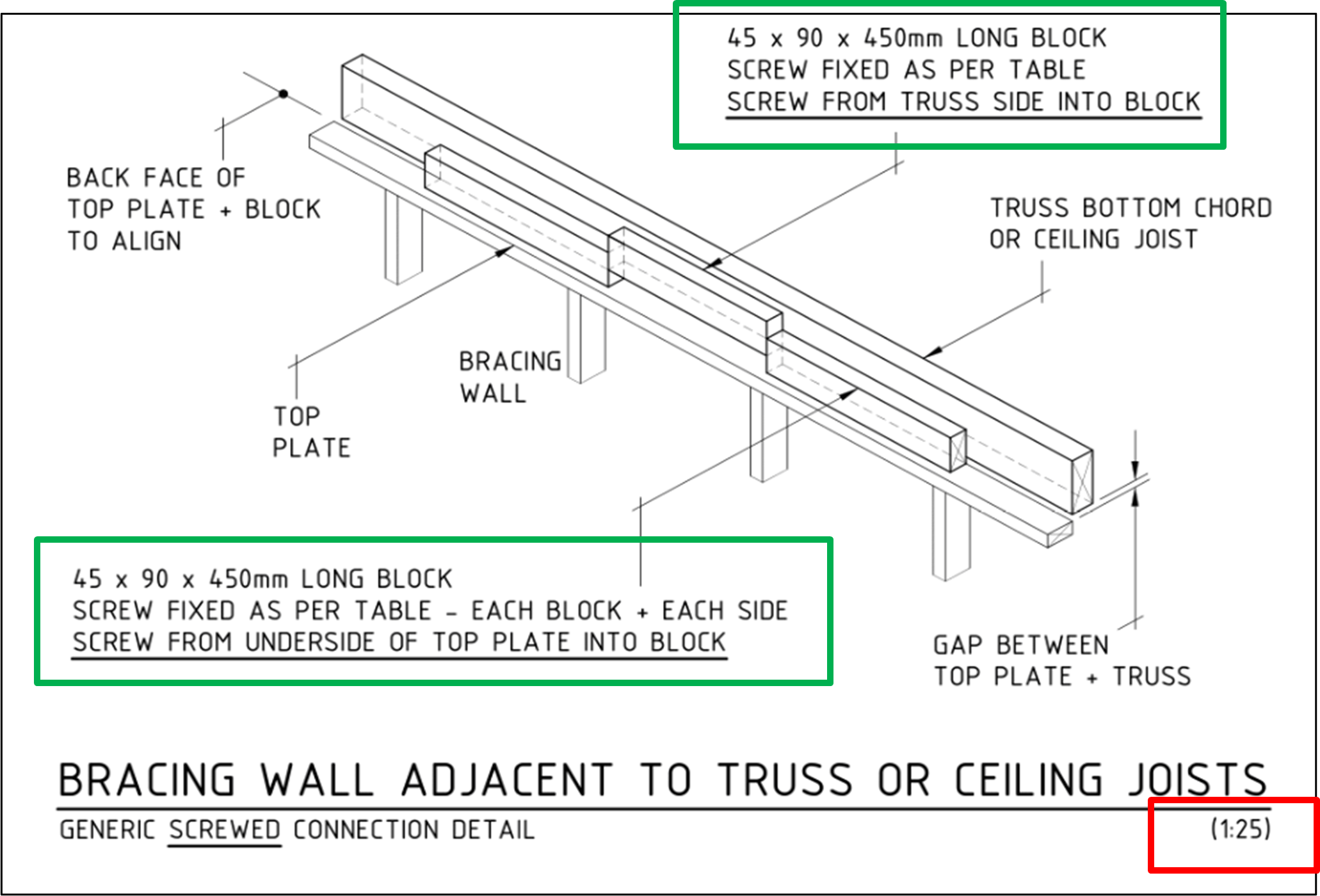
For wall bracings, specifically wall bracing adjacent to ceiling joists, you can use solid lines to outline wall studs, ceiling joists, and the truss bottom. You can project these orthographically, although it is much better to use isometric projection since it gives you a better grasp of the details. Your output would look something like the image here.
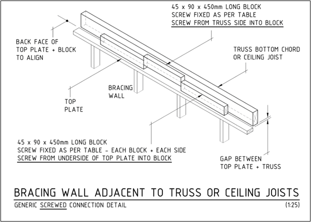
Based on the image, you can see that labels are used to provide a textual description of important parts of the drawing, such as the measurement for long blocks. Additionally, the label specifies the position of the ceiling joist or truss bottom chord relative to the wall bracing top plate.
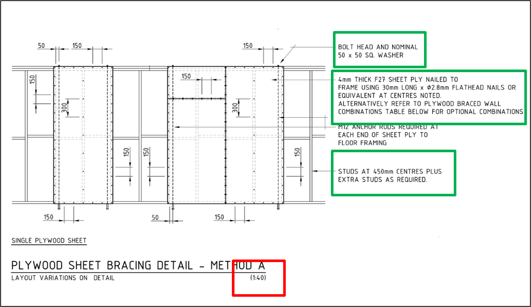
For the details regarding plywood sheet bracing, your output would look like something this.
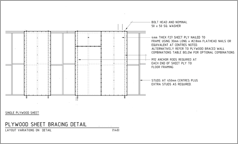
As you can see, solid lines and dashed lines are utilised in this orthographic drawing. Measurements for the nominal washer, sheet ply thickness, and spacing of wall studs, all of which are required based on the initial client brief, are specified here and labelled accordingly.
Non-structural component
Since the requirement is to see the front building façade, it is best to project the building orthographically for a full front view. Use solid lines to outline the form of the building and attach labels corresponding to the client requirements. Your output should look like the image shown here.[10]
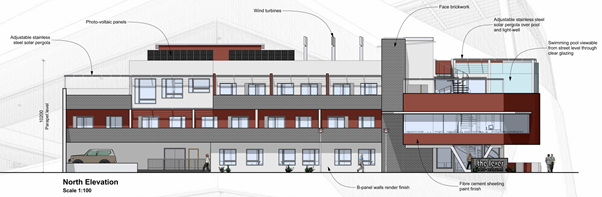
Access Front Elevation here.
As you can see in the image above, elements such as windows, doors, and others visible on the front façade are shown. Additionally, you can see walls are labelled according to the type of finish to be employed and the height of the building.
Scales
Scale refers to the ratio that dictates the size of scale drawings, which are drawings used for accurately illustrating real-life building components or items at fixed, reduced, and enlarged sizes. These scale drawings can be measured with a scale rule to determine their actual size.
Scales are especially significant in illustrating the drawing so that the details of the object are captured and ensuring that the object fits in the drawing sheet. When objects are scaled up, one can see and examine the intricate details of a component better.
Refer to the table below for some examples of the ratio of standard scale ranges and their corresponding description.
|
Ratio |
Description |
|
1:100 |
|
|
1:2 |
|
|
1:1000 |
|
|
1:50 |
|
Dimensions
Dimensions are numerical values expressed in units of measurement, defining the size of an object, including length, width, height, thickness, and the like.
The metric system is used (unless otherwise indicated) since Australia uses the metric system. Thus, you can see in the plans that the units metres (m) and millimetres (mm) are typically used to define the dimensions. However, there are cases when these units of measurement are not indicated in the plans. Still, this should not be a cause for confusion since the presence of decimal points or commas, or the numerical values themselves, imply what unit of measurement (i.e. whether millimetre or metre) is being used.
Below are ways of how dimensions can be displayed in construction drawings:
- Using decimal points. In some cases, decimal points may be used in displaying the dimensions of certain objects. Values may be rounded off to either two or three decimal places. (e.g. 2500.00 or 2500.000)
- Using comma or space as a thousands separator (e.g. 2 500 or 2,500). However, you may opt not to use this as there are many cases where values are displayed without a comma or space.
- Using dimension terminators such as dots, arrowheads, or slash to indicate which point the measurement starts or ends. Dimension lines and terminators will be discussed in more detail in a later section.
- In some cases, building components are not drawn with dimension lines and terminators but are displayed in the 'length x width x height' format. For example, one unit of a concrete hollow block (CHB) may be displayed as 230 x 110 x 76.
Use scales and dimensions to detail vital information
With the knowledge you gained from the previous sections regarding scales and dimensions, you can now add information to the 2D and 3D drawings you created.
To illustrate this, the example from the previous section will be used.
Structural component
If you closely examine the drawing from the previous section, you will see that the drawing conventions of scale and dimensions are already incorporated. The drawing, shown again here with highlights[11] is created with a scale of 1:25 (refer to the red box). Remember that the appropriate scale depends on the level of detail you want your drawings to have. Therefore, you can enlarge the drawing using a scale that magnifies the drawing better, say 1:10, when necessary. However, take note that a larger scale takes up more drawing space.
Dimensions, on the other hand, are displayed in the format 'length x width x height' (refer to green boxes). This type of formatting is applicable when you are trying to save drawing space or when the object can be described sufficiently using the format. However, there are those that require the use of dimensions lines. You will see them in the subsequent discussions.
On the plywood wall bracing drawing, you can see that the scale employed is 1:40 (refer to the red box). For this drawing , some dimensions are incorporated in the labels (green boxes), similar to the drawing above, and others use dimension lines and terminators.
Non-structural component
Based on the drawing of the front building façade here[13], you can see that the drawing is scaled 1:100 (see lower left side of drawing). Additionally, you can see the dimension of the height of the building from ground floor level to roof level parapet (see height indicator on left side of drawing). The dimensioning for this drawing involves the use of dimension lines and terminators (i.e. slash).

Access Front Elevation here.
In summary, you must always incorporate scales and dimensions to detail your drawings further. Ensure that labels for scales and dimensions are written clearly without any lines or other drawing elements distorting the scale and dimension labels.
Sections are views showing how a structure looks with respect to an imaginary vertical plane that cuts through it. This imaginary cutting plane allows one to see through the structure's interior, which is otherwise concealed by the exterior walls. It illustrates the 'sliced' view of the building or building component. Details that can be obtained from section views include:
- Variations in the elevations of a single floor level
- Floor-to-ceiling height
- Building height
- Roof height
- Dimensions of doors, windows, and other openings
- Dimensions of fixtures, furniture, and equipment
To produce sectional drawings, you need to adhere to the following guidelines:
- Use hidden lines (characterised by dashes and short, broken lines) to convey hidden edges and surfaces. You can also use them as dimension terminators, if applicable.
- Label each part of the section clearly.
- Use the standard conventions for shading/hatching to represent the material required in the sectional drawing.
To illustrate this task, refer to the image below[14]. This image is the sectional view of the building used in the previous section.
Access Section View here.
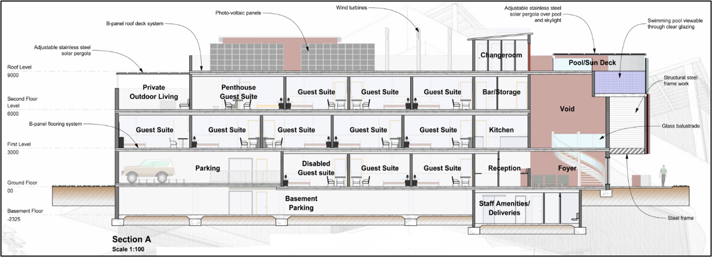
To create the sectional view, use the building front view — the main drawing produced in the previous section — as your reference. After, you must make a vertical 'slice' on the portion of the building whose elements and components need to be identified and labelled.
Use thick solid lines to outline elements and components (e.g. floors, walls, etc.) included in the vertical slice. As you can see, the walls and floor of the different spaces or rooms in the building are outlined with solid lines and hatched or filled appropriately.
The legend below explains the composition of the items:
 Soil – this hatch indicates soil
![]() Concrete – this type of fill indicates floors made of concrete
Concrete – this type of fill indicates floors made of concrete
![]() Columns – this type of fill indicates posts or columns
Columns – this type of fill indicates posts or columns
Now that you have outlined all 'sliced' elements and components with solid lines, you can outline the elements and components that are not directly 'sliced' (i.e. elements behind the 'sliced' portion) with lighter solid lines. In the section view shown earlier, you can see that some elements and components (e.g. doors, the car in the parking area and the photo-voltaic panels and wind turbines on the roof level) are outlined with lighter solid lines to indicate that these are positioned behind the vertical slice.
Next, label the building spaces or rooms appropriately. As you can see in the section view drawing discussed earlier, labels to indicate the space function such as guest suite, private outdoor living, parking, basement parking, etc., are attached. Make sure that the labels are formatted and positioned in a manner so they can be easily read.
Lastly, attach the necessary dimensions. As in the section view drawing discussed earlier, the measurements of the floor elevations are attached on the left side. You may opt to place it on the right side, as long as the text and values can be read easily and clearly. Additionally, you must use dashed lines (as in the section view drawing) to indicate the start and end of a particular measurement (e.g. use dashed lines to indicate where the ground floor starts and ends).