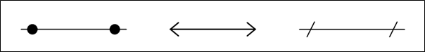
Dimension lines
Dimension lines indicate the main object's measurements and are often drawn as light, fine solid lines with terminators on each end. Terminators may be arrows, slash or thick dots. Refer to the image below for examples of dimension lines.
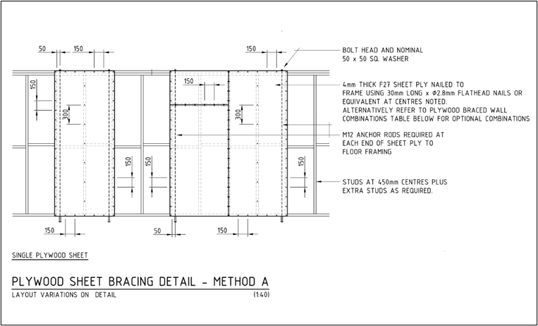
It is significant to note that dimensions and dimension lines go together to provide further detail for the elements and components included in your drawing. For example, the image here shows the plywood sheet bracing detail used earlier, now shown with dimension lines.
As you can see in the drawing, dimension lines indicate the spacing of flat-head nails screwed to the plywood wall brace. For the dimension lines employed, arrows are used as the dimension terminators, and the dimension values are mostly placed at the left side of the dimension lines.
In applying dimension lines to your drawings, ensure that dimension lines cover the full extent of the element or component that you are measuring. You can use the same rule of using arrowheads as dimension terminators. If applicable, you can place the dimension values at the centre of the dimension line instead of placing the dimensions on the left side of the dimension lines. Additionally, make sure that the dimension lines do not overlap with the dimension values, as this will make the dimension values or numbers difficult to read.
Symbols
Symbols refer to icons commonly used in building and construction to convey information, such as the location of components to the end-users. They often refer to fixtures, placements, and important elements such as electrical and gas outlets. Most symbols are universal, so it is easy for builders to recognise where fixtures are located by referring to the symbol legend on the drawings.
Below are common symbols you usually encounter in construction plans that you can apply in your drawings.
|
What it means |
|
|
|
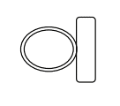
Water closet (plan view) |
|
|
Tree (plan view) |
|
|
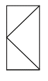
Right-hinged door (elevation view) |
|
Symbol |
What it means |
|
|
North Arrow |
|
|
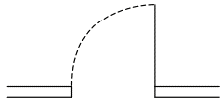
90-degrees single-swing door (plan view) |


Other symbols can be found in the 'Legend' portion of a particular sheet. Refer to the image below for examples of symbols contained in the legend.
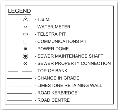
Note that you may not encounter exactly the same symbols in different construction plans since the elements and components vary from project to project. However, these symbols follow the provisions in AS 1100.
When applying symbols in your drawings, you must:
- Ensure that the symbol is appropriate to the element or component you are describing or referring to. In other words, double-check if the symbol you are using to describe a door is a door symbol and not a window symbol.
- Avoid placing symbols where they overlap with other drawing elements such as lines, shading, etc. Symbols must be placed where they can be easily read to avoid confusion or ambiguity.
- Provide a 'Legend' portion where lesser-known symbols are briefly described. Putting a 'Legend' portion in your drawing simplifies your drawings and makes them more organised since the textual description is fixed in one place and not all over the drawing sheet.
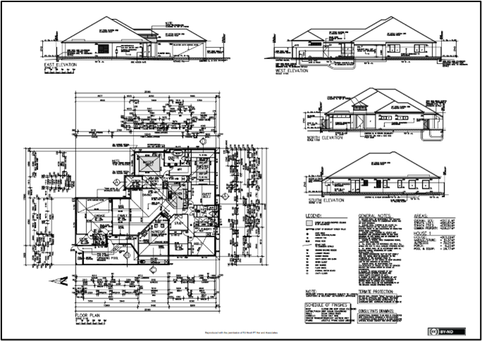
To guide you in making a 'Legend' portion, refer to the sample plan below and observe how the legend is organised on the lower right quadrant of the sheet.[19]
Access Section View here.
Abbreviations
Like symbols, abbreviations are shortened forms of common construction terminologies that can be used to represent key information in your drawings. Abbreviations are an important part of any drawing as they keep drawings clear and make them easier to read. By simplifying notations using abbreviations, drawings remain clearer and not cluttered with information that would otherwise make them hard to read and may even cause issues locating important information.
Common abbreviations are contained in the document AS 1100 referenced earlier. Some abbreviations you can use in your drawings include the following:
|
Abbreviation |
Meaning |
|
AL |
Aluminium |
|
AO |
Access opening |
|
AS |
Australian Standard |
|
B |
Basin |
|
B/I |
Built-In |
|
BK |
Brick |
|
BTH |
Bath |
|
BV |
Brick Veneer |
|
BWK |
Brickwork |
|
CAB |
Cabinet |
|
CF |
Concrete Floor |
|
CJ |
Ceiling Joist |
|
D |
Door |
|
DG |
Double Glazing |
|
DW |
Dishwasher |
|
HBD |
Hardboard |
|
HTR |
Heater |
|
HW |
Hot Water Unit |
|
HWD |
Hardwood |
|
INSUL |
Insulation |
|
KIT |
Kitchen |
|
LIN |
Linen Cupboard |
|
NGL |
Natural Ground Level |
|
O |
Oven |
|
REFRIG |
Refrigerator |
|
RS |
Roller Shutter |
|
RSJ |
Rolled Steel Joist |
|
SD |
Sewer Drain |
|
SD |
Sliding Door |
|
SHR |
Shower Recess |
|
SWD |
Stormwater Drain |
|
TC |
Terra Cotta |
|
TEL |
Telephone |
|
UTIL |
Utility |
|
VENT |
Ventilator |
|
WM |
Washing Machine |
|
WR |
Wardrobe |
|
VB |
Vanity Basin |
|
WC |
Water closet |
|
FW |
Floor waste |
When applying abbreviations, you will be employing more or less the same principles in applying symbols (discussed in the previous section). You must:
- Ensure that the abbreviation is appropriate to the element or component you are describing or referring to. For example, when describing a dishwasher, use 'DW' and not 'D', as 'D' stands for Door.
- Avoid placing abbreviations where they overlap with other drawing elements such as lines, shading, symbols, etc. Abbreviations must be placed appropriately for easy location.
- Include the abbreviations you used, especially the lesser-known ones, in the 'Legend' portion where they are briefly described. This simplifies your drawings and makes them more organised since the textual description is fixed in one place and not all over the drawing sheet.
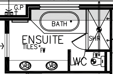
For example, say, you are drawing the floor plan of a residential building, specifically an 'Ensuite'.
You would need to add the following abbreviations to your drawing:
- VB on, or next to the vanity basin symbol
- MC next to the water closet symbol
- FW next to the floor waste symbol (shown as a cross next to the word “TILES”)
- SHR on, or next to the shower recess symbol
The symbols and abbreviations are shown in the drawing here.
You would need to add the following labels to your drawing:
- VB on, or next to the vanity basin
- MC next to the water closet
- FW next to the floor waste symbol (shown as a cross next to the word “TILES”)
- SHR on, or next to the shower recess
Refer to the list below for the components and their corresponding description:
- Job title
Job title refers to the project name and project details, including client information and site address.
- Date
Date refers to the actual date the drawing was initially drawn.
- Scale
Scale refers to the scale the drawing has been plotted or printed to convey size. Note that on some sheets, drawings are presented in different scales. Thus, the corresponding scales for each drawing must be noted.
- Sheet number
Sheet number, or drawing number, refers to the unique number applied to a drawing for identification and reference.
Sheet layout
Sheet layout refers to the arrangement of all drawings, including the title block (covered in the subsequent discussions), in the drawing sheet. The sheet layout for all types of plans (i.e. house plans, floor plans, site plans, elevations, etc.), when drawn, should be compliant with the Australian Standard AS 1100, Part 3 Architectural Drawing. The standard outlines where items should be located on the page and how different design elements should be drawn, abbreviated, and annotated.
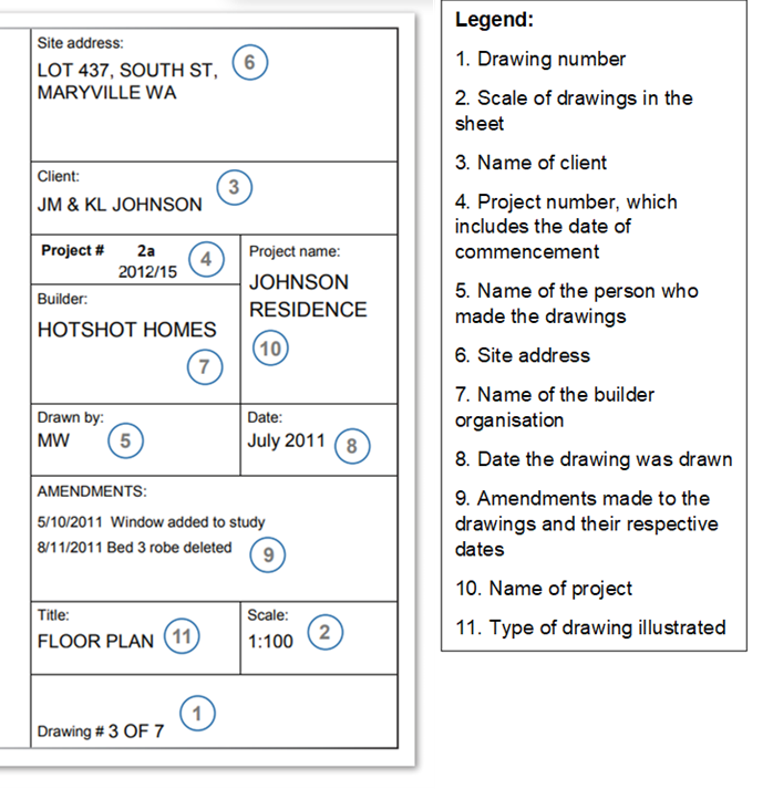
Title block
A title block is an important element of any drawing or plan and provides vital information to assist in reading and understanding the document. Therefore, every drawing sheet will have a title block. Usually, you will find the title block located on the bottom right-hand corner of the drawing sheet or, sometimes, at the top right corner, depending on the architect or building designer.
The title block will show important administrative details, including:
- What type of drawing it is (i.e. site plan, floor plan)
- Details of architect or building designer, such as name and contact details, and the name of the person who drafted the drawing
- The address or the location of the site
- The name of the client
- The date the plan was drawn
- The drawing or revision/amendment number
- Signatures, initials, and dates
- Scale of the drawing
- Total floor area in square metres (m2)
- Glossary of terms
While different builders might present their designs slightly differently depending on their preference and the software they use, it is still essential that the information is presented clearly and accurately.
An example of a title block is presented below.
Once you complete the sketches and add all the relevant information, you will need to produce the completed drawings in the appropriate form.
The illustrations below demonstrate the type of sketches in their final form. As you go through the discussions below, it is important to note that the title block is present in each drawing sheet since it is a vital part of a completed drawing.
Cover sheets
Generally, cover sheets feature the exterior of the house by displaying the perspective view of the building. In the sample plan below, you can see two perspectives provided for the viewer to grasp what the house looks like.
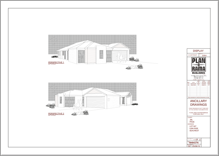
Usually, each organisation follows a template or format for presenting completed drawings. For this reason, cover sheets from different building organisations differ. In some cases, cover sheets provide a brief overview of the project plan, including placements, information and layouts. Additionally, builders will also include general notes which apply to the entire build and contains information such as:
- Material requirements and properties
- Bushfire protection requirements
- Structural notes
- Notes for other contractors
Floor plans
Floor plans show the layout of a structure or property from above. The illustration below demonstrates the type of information you need to include in the floor plan.[23]
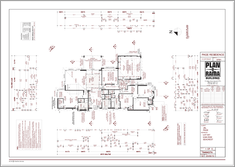
You need to ensure that measurements are accurate and precise before signing off the final floor plan. A wide range of stakeholders and contractors will be relying on the floor plans to determine positions, fixtures, material costs and labour costs. Mistakes found after construction commencement may lead to change orders, extended deadlines, and require a new set of drawings to be produced.
The final presentation of a floor plan will include the following information:
- Notes and legend
- Title block
- Measurements and dimensions
Elevations and sections
Final elevation and section drawings will need to be presented in the following format, as illustrated in the image below.
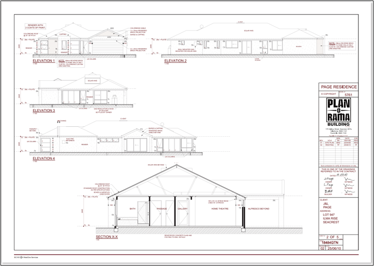
Elevation drawings must illustrate all sides of a building to give a complete and final picture of the building structure. They must also contain all the necessary information to be submitted to the local council for approval. The information must be clearly labelled and include precise and accurate measurements of the building structure.
Builders must check the final elevation drawings for mistakes before presenting them. Check for:
- Incorrect labels
- Inaccurate measurements
- Wrong scale
- Incomplete drawing
For every sheet you make, you need to include information such as:
- Dimensions
- Scale
- Title block
- Notes
- Section number
- Type of view