
What is a project plan?
Project plans for building and construction projects allow project managers to get a bird's-eye view of all the tasks and activities necessary to finish a project. Project plans also provide an understanding of the resources required for the completion of each job. A project plan discusses how the project will be designed, coordinated, and controlled to complete the work needed on schedule within the budget and within the specifications required.
The main factor in formulating the project plan is the contracting plan, which answers many questions. Contracting plans do not address government and social restraint questions, building capital, owner's policies or legal conditions, and contractual requirements affecting the project schedule. During the creation of the project implementation plan, answers to these questions must be sought.
There are several types of plans that may be created for a specific building project. The bare minimum that a set of plans for a building project has usually includes:
- Site plan
- Floor plan
- Elevation
- Section
More detailed plans are created by specialists involved in the building and construction project, such as architects, designers, or engineers. These specialists often create plans in consultation with the client.
The plans include specifications that define the specific information that can't be shown or described in detail on the plans or drawings. The following are examples of the type of information you might find in specifications:
- Task details and work environment
- Tools and materials to be used
- Safety and environmental requirements
Several other specifications may be presented, and compliance methods will vary from organisation to organisation. For example, one organisation might require its workers to use a Dumpy level when setting out, while another organisation might require its workers to use a Y level. Some organisations may even require specific types of levels depending on the type of building being constructed or the terrain of the construction site. Always refer to your organisation's policies and procedures before proceeding with setting out.
The project management plan will be reviewed and evaluated as the work progresses. Minor variations are normal, but be extremely cautious with significant changes. The project plan will include how long each assignment will take and the correct sequence.
It is important to get any current project plans in your organisation so you can source, read, and follow them. It is good to take notes so that you will be able to effectively apply the contents of the project plans. You must simplify and break down what the project plans contain so that you can better understand them.
Construction drawings and specifications
Construction drawings and specifications are usually included with the contract documents of a construction project. The drawings and specifications of a construction project give the builders all the information they need to construct a specific building in a construction project.
Construction drawings serve as graphical illustrations of the building project design. These serve as an integral tool before the commencement of a construction project. The visualisation of a project allows a sharper perspective of work, better preparation, and accuracy of specifications. Specifications detail the materials, standards, techniques, and all other information not included in the construction drawings required to carry out construction works on the project.
The following are information included in construction drawings and specifications:
Building codes the project refers to
- Colour selections
- Contract requirements
- Material and labour schedules
- Materials specifications
- Plans, sketches, and drawings
- Statements of requirements
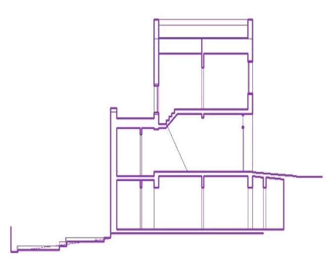
Section drawing
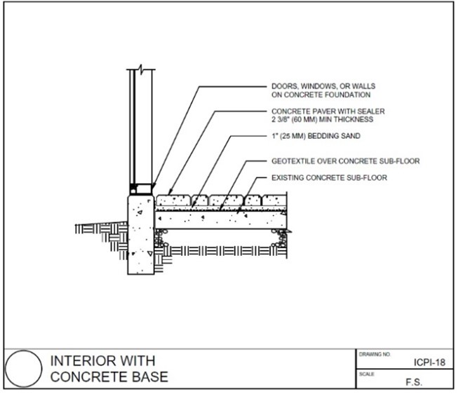
Detail drawing
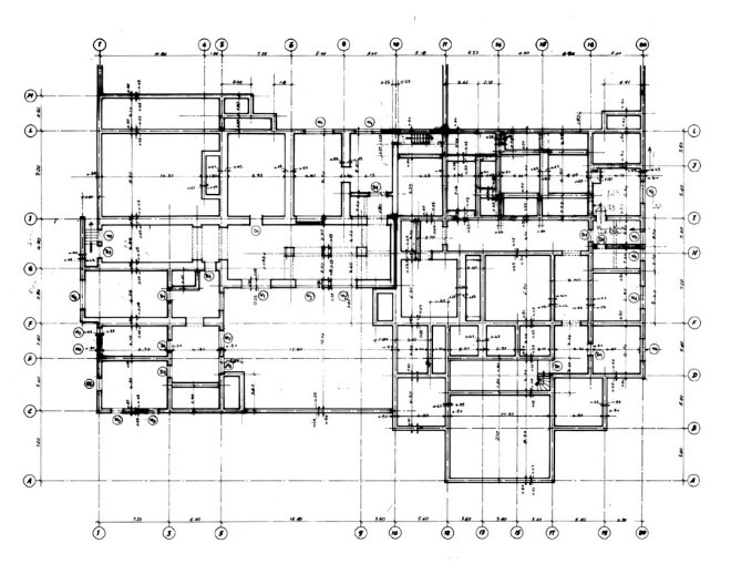
Floor plan
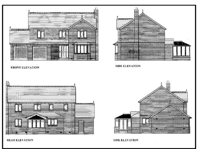
Elevation drawing
Construction drawings are categorised according to type. Each type of drawing represents a specific function or portion of a construction project design. Below are some examples of typical construction drawings:
Site set-out procedures
You must become familiar with sourcing, reading, and following established site set-out procedures.
A carelessly planned building would be difficult to build and costly to maintain and potentially unsafe. So, take extra care when setting out.
For setting out, there are three main steps:
| 01 | 02 | 03 |
| The building's orientation on the site | Marking a clear outline on the ground of the base of the building | Placing 'batter boards' across the outline of the base |
Orientation
A building's orientation is the direction its front walls face: north, east, south, west, or something else in between.
Find north first to mark the orientation on the site. It is best to do this with a compass, either a physical device or built into a smartphone app. However, if there is no compass available, there is still a way to find north.
On the building plot, the builder should stand so that their right arm points to the spot where the sun rose in the morning, while the left arm points to the spot where the sun set the previous day. The builder will be facing the north in this position.
If the builder moves their arms out equally to form a straight line, they will point west (left arm) and east (right arm).
Use a stick to mark the shape and location of the building once you have identified the principal compass points. Next, add about two metres to the building's dimensions on all sides; this extra space will be used to store supplies and workspace during construction.
Next, clear the area of trees, shrubs, and loose plant growth, and if the topsoil is loose, clear the top 15 centimetres or so to get down to hard ground.
If it is too difficult to clear the land or the site has trees that offer shade or beauty, consider moving the building a short distance.
Marking the outline for the base
- The next move is to use strings and pegs to mark the outline of the base on the site.
- There are three very important steps:
- Accurately mark the length of each wall; the string must be exactly level; the corners must be square: exactly 90°
- On level ground, the length of each wall is simple to set. Simply set it with a tape measure, making sure the tape is taut.
- When the site is on rough terrain, determine the length of the wall in a level line.
The following procedure is for marking the outline on unlevel ground. Start at the highest end of the length of the first wall. Tie the string to a peg planted at the endpoint. To prevent the string from sagging, set a new peg every 2 m. Ensure that the string is level by using a plumb bob and mason's square. Set the plumb bob and wait for it to stop swinging. This will indicate a vertical line. Next, use the mason's square to check the string is exactly level.
Repeat this step until the set string length is equal to the first wall's expected length.
Batter boards placing
First, locate the highest point on the site about one metre beyond the outer foundation line to place batter boards around the construction location and place a wooden stake firmly in the ground.
Nail this stake to the first board so that the top of the board is at least as high as the base wall. Since the base walls must be at least 20-30 centimetres above the ground, this would be as high as the floor.
Next, put a second stake outside the outer foundation line, two metres from the first. Nail the other end of the first batter board to it, checking that the batter board is level. Nail a second board to the same stake and repeat the process of putting new stakes, levelling, and nailing the boards until the batter boards create a fence that goes fully around the building position.
Following site set-out procedures
One of the main stages of construction is setting out the shape and size of a house. Any errors made at this point would have a significant effect on the rest of the construction process.
In sourcing, reading, and following the site set-out procedures, you must memorise the main points of the procedures and apply them at the construction site. It is good to have a bulletin board of the procedures fastened onto a wall so that all the construction employees can refer to them. Simplify the original wording of the procedures into a summarised version as a reminder for employees.[6]
Design principles

Using appropriate orientation
Windows and doors should be shaded from the summer sun by eaves, pergolas, sun hoods, or external blinds. Effective shading can block up to 90% of the heat from direct sunlight, reducing heat from north-facing glazing in summer. Shading devices may be fixed or movable and should be correctly placed and sized to respond to the sun's height at different times of the year. As a basic rule, north-facing eaves should be narrow enough to allow the low-angle winter sun to enter the house, but wide enough to block the high-angle summer sun. The type and size of these devices will vary depending on your climate zone, location, and budget. Shading of buildings reduces summer temperatures, improves comfort, and saves energy. Direct sun can generate the same heat as a single bar radiator over each square metre of a surface. Effective shading — including eaves, window awnings, shutters, pergolas, and plantings — can block up to 90% of this heat. Shading glass to reduce unwanted heat gain is critical, as unprotected glass
is often the most significant source of heat gain in a building.
Provide appropriate levels of insulation
Building insulation stops the unwanted transfer of heat from inside to outside and vice versa. In winter, it ensures that heat from mechanical heating or the sun is kept inside the house, and in summer it prevents the cooling effect from air conditioning or thermal mass inside the house from escaping. Insulation is generally placed in ceiling spaces, under roofs, in walls, under suspended floors and sometimes underneath and around concrete slabs. Insulation is important in all climate zones but is particularly relevant in colder climates where insufficient insulation allows heat to filter out through ceilings, roofs, walls, and floors.
Insulation acts as a barrier to heat flow and is essential for keeping buildings warm in winter and cool in summer. It can also help with weatherproofing and soundproofing. A well-insulated and well-designed building provides year-round comfort, cutting your cooling and heating bills by up to half and reducing greenhouse gas emissions. Climate conditions determine the appropriate level of insulation and the most appropriate type to choose — bulk, reflective or composite.
Principles of establishing control during set-out surveys
Control marks should cover the entire area of the project, be intervisible to each other, and be placed close enough together so that later survey work can be carried out anywhere on the project to a sufficient accuracy.
Measurements for the control survey should be made to a uniformly high standard of accuracy.
Control marks must be as stable as possible, preferably anchored firmly to bedrock, and located where the risk of damage (for example, during construction) is minimised. The erection of a framework around the mark is often done for protection.
Control marks should be positioned on high ground, if possible, near where they will be used (for example, collecting topographical information, setting out during construction, making check measurements upon completion of the project).
Control marks are referenced to aid recovery of the point should it be disturbed.
Application of building set-out
You must set-out a building that is more than a plain rectangle. In addition, you must ensure all of the following are also done:
- Check level with 2 peg test.
- Set up level to set-out building.
- Mark out setback from front boundary and string line for this.
- Mark out setback from side boundary.
- Square the side of the building using 3-4-5 triangle set-out.
- Construct profiles for overall measurements of building and ensure levels are the same.
- Check rectangular measurements and ensure that the set-out is square by checking the diagonals.
- Mark out all external walls and offsets.
With your current project plans, you must have technical skills to use digital tools and devices to communicate and collaborate effectively with others and use equipment and programs to access and extract information and develop relevant documentation.

Levelling devices
The selection and use of levelling devices must be in accordance with standard operating procedures (SOPs). However, before learning what the standard operating procedures are, you must understand what levelling devices are.
Levelling devices are the various instruments used for levelling in surveying. There are various sorts of levels. The method of measuring vertical distances in surveying is named levelling.
To perform levelling, you must know about levelling devices appropriate to the construction site. With technology introduced to surveying, many easy to use measuring instruments are available.
Types of levels utilised in levelling
The following are the kinds of levels used in surveying:
Dumpy level
Dumpy levels are the most commonly used levelling instruments. A Dumpy level uses a telescope attached to a tripod or similar support. A bubble level is affixed on top of the telescope to indicate the level is upright.
While the horizontal movement of the telescope itself is limited, the levelling head can usually be rotated in the horizontal plane with the telescope. A staff is moved to different positions on the construction site. The relative vertical height of these positions can be found by reading the scale on the staff through the telescope.

Y level
A Y level (or Wye-level) is made up of a telescope supported by y-shaped frames attached to a vertical spindle so that the telescope can be rotated. The telescope of a Y level can be detached from the supports.
Unlike a Dumpy level, adjustments can be quickly tested using a Y level. However, these quick adjustments can lead to frictional wear of the open parts of the level.
Cushing’s level
Like a Dumpy level, a Cushing's level has its telescope fixed and cannot be rotated. However, the object end and the eyepiece end of the telescope can be swapped.
Tilting level
A tilting level consists of a telescope with horizontal rotation and tilting of about four degrees in its vertical plane. The centring of the bubble is easier with a tilting level. However, for every setup, the bubble has to be centred with the help of a tilting screw. The main advantage of a tilting level becomes apparent when only a few observations need to be taken.
Cooke’s reversible level
Cooke's reversible level is a combination of a Dumpy level and a Y level. The telescope of Cooke's reversible level can be reversed without rotating the whole instrument. The bubble left and the bubble right reading of the telescope removes collimation error.
Automatic level
Automatic levels are like Dumpy levels. The telescope of an automatic level is fixed to its supports, usually with a bubble level to set it approximately upright. A compensator is attached inside the telescope to provide more accurate level readings.
Checking the compensator involves manipulating the foot screws. If the levelling staff remains constant, then the compensator is configured correctly.
Electronic distance measuring equipment
Electronic distance measuring equipment (EDM) emits a light beam towards a prism or target held at a point to be mapped. The light beam reflects back to the EDM and the device compares the timing of the emitted light and the reflected light. This allows the EDM to accurately determine the distance between the unit and the target surface.
The EDM can also measure the azimuth (angle from north) and the elevation of a point.
Data obtained through the EDM is stored in a data collector and downloaded for processing using software.
Laser level
Manual laser
A manual levelling laser requires the operator to manually level the unit by turning the thumbs screws and getting the unit levelled by looking at the bubble vials.
The v-groove shape of the device fits contours of pipe and conduits.
Dot laser
It allows the user to establish plumb lines or right angles by projecting laser dots vertically, horizontally, or at right angles. It can project two, three, or five laser dots at the same time.
The laser dot projected can transfer a point from the floor to the corresponding point directly above it on the ceiling and establish a level plane.
Optical level
The unit is composed of a precision telescope with crosshairs and Stadia marks. The crosshairs establish the level point, while the Stadia marks allow range-finding.
The instrument's level is adjusted by coarse adjustment of the tripod legs and fine adjustment using the precision levelling screws on the instrument.
The Stadia marks on the precision telescope are usually at ratios of 100:1.
The precision telescope is mounted on a tripod. This telescope can freely rotate 360° on a horizontal plane.
Water level
This type of level utilises the surface of liquid water to establish a local horizontal plane of reference. It uses approximately two litres of water inside a clear plastic tube, 6-10 millimetres diameter and about 14 metres long. Dyes can be added to the water to make it more visible.
Theodolite
A theodolite uses a combination of optical plummets, a bubble level, and graduated circles to determine the vertical and horizontal angles in surveying.
The optical plummet helps the surveyor set the theodolite vertical above the survey point. The internal spirit level makes sure the device is level to the horizon. The graduated circles allow the surveyor to survey for angles.
Digital versions of theodolites have an electronic readout screen that displays the horizontal and vertical angles. These digital theodolites provide more accurate readings.
Standard operating procedures
The construction organisation you are working for will state the type of levelling devices you must use for site set-outs in their standard operating procedures (SOP). SOPs are descriptions of the processes behind an operation or mission. They are written guidelines that clarify the work measures you use to enforce the processes and policies for construction quality.
ISO 9001
The need for an SOP and a quality control system where a company can demonstrate its ability to meet consumers' expectations, stakeholders, and any relevant regulatory requirements is defined by ISO 9001, the international standard for a quality management system.
Applications
A standard operating procedure provides uniformity to how procedures or activities are performed by formalising processes. It also advises new staff about relevant company strategies and procedures.
The general essence of the instructions is what separates a normal operating procedure from a highly complex Method of Procedure (MOP) and recording precise step-by-step instructions. It is possible to integrate a procedure method (or multiple procedure methods) into regular operating procedures.
Standard operating procedures are widely used to document production processes and health and safety policies.
A typical SOP includes the following detail:
- responsible individual(s)
- procedure
- purpose
- reference
- scope
In selecting and using levelling devices, you must always check the SOPS to gauge and know the proper levelling device for use in a specific construction site. Be aware of updates to the SOPs of your construction organisation.
Levelling inaccuracies may be caused by human error, with the surveyor making mistakes during set-up or operation. Errors may also be due to faulty equipment. Therefore, verification of the level is essential. The main reason for level errors is when the line of sight is not parallel to the horizontal line of collimation. The two-peg test is a standard method to verify levels. This test measures the degree of error and notifies the technician that the level may require servicing.
It is important to apply the two-peg test to check the errors in the levelling instrument because any error will significantly affect the site set-out.
Applying the two-peg test
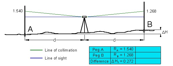
A method to check this common error is the two-peg test. To apply this test, you must establish two points (pegs) approximately 50 metres apart. Set the level halfway between the two points of the instrument.
From the level instrument, take the two staff readings. The difference between the two reading is the difference in elevation of the two points. If there is an instrument error, the same error will apply to both readings as the points are the same distance away from the instrument, and, in effect, the error will cancel out when finding the difference in elevation.
Now, move the level to near one of the points and take staff readings for both points. Find the difference in elevation of the two points again. An instrument error will be greater over a larger distance, so in this situation, any level error will not cancel out as before.
If the line of sight does not coincide with the line of collimation, there would be a significant difference between the two values for the difference in elevation.
The amount is okay if the gap in height is the same. If it is not, the level device needs to be serviced. The example given below shows that the level instrument has an error because there is a height difference of 0.272 between Peg A and Peg B.
To carry out reduction in a closed level run in levelling work, you must be familiar with the underlying concepts and apply appropriate methods.
Reduced level
In surveying terms, a reduced level is an elevation measurement made referenced back to a fixed point or datum. It is a vertical distance between the point of the survey and the adopted data plane.
In levelling work, there are two main methods for calculating reduced levels. These are:
- rise and fall method
- height of plane collimation method
There are two types of level runs: closed and traverse.
A closed level run is one that begins and ends with a fixed benchmark. The run may loop back to the same existing datum benchmark or to a different one. An advantage of this type is that it is easier to uncover surveying errors as the final elevation is known, so the last reduction should match the last benchmark.
A traverse level run is one that starts with a benchmark but does not finish with one. This run does not include the verification that a closed run does.
Rise and fall method
In the "rise and fall" method of reduction, each pair of successive readings is compared and referenced to a series of different points. The relative rise or fall is measured and added to the reduced level (RL) of the first staff station to obtain the RL of the second. Except for compensating errors, the complete "rise and fall" method offers a clear but absolute check on the arithmetic.
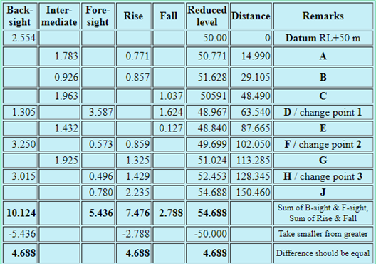
Here is the following procedure for the rise and fall method:
- Calculate the rises and falls between successive points and record them in the appropriate column of a table as shown in the example below. The following rule of thumb may be used to decide whether a measurement indicates a rise or a fall: A higher value at the top indicates an upward trend, while a higher value at the bottom indicates a downward trend.
- Calculate the difference between the backsight and foresight columns for the entire traverse; this will close the traverse.
- Add up the rises and falls for the whole traverse and compare them to the disparity between the backsights and foresights; they should be the same.
- By adding or subtracting the required rise and fall values to the successive RL values, bring the reduced levels in the RL column down the page. By the sum of the end, the final value of the original starting point will vary from the original value.
- The discrepancies between total backsights and foresights, total rises and falls, and beginning and finishing RLs should be the same if the levelling was performed correctly and all arithmetic reductions were accurate. This gap is the nearest, and it should be within 2mm or 6mm, depending on which water-level standard is being followed, 3mm or 10mm for site inspection purposes.
The Rise and Fall Method is the method used in levelling work to measure the difference in elevation between consecutive points.
The millimetre reading may be taken by estimation to an accuracy of 0.005 metres or even less.
- Backsight, intermediate sight and foresight readings are entered on separate lines in the required columns. However, as seen in the table above, if you adjust the level tool, backsights and forecasts are put on the same side.
- The datum height, benchmark or RL is the first reduced level.
- The gap between the two readings is put in the rising column if an intermediate sight or foresight is smaller than the immediately preceding staff reading.
- The difference between the two readings is put in the fall column if an intermediate view or prediction is greater than the immediately preceding staff reading.
- The previous RL is applied to a rise and a decline is subtracted from the previous RL.
Check for arithmetic
Although it is possible to verify all arithmetic calculations, there is no guarantee that errors in the field procedure will be picked up. The arithmetic check only proves that the rise and fall is correctly recorded in the appropriate rise and fall columns. To check the field procedure for errors the level traverse must be closed. To prevent a repeat of the level run, it is wise to let another person review your reading.
If the arithmetic calculation is correct, the difference between the sum of the backsights and the sum of the foresights will equal:
- the difference between the sum of the rises and the sum of the falls, and
- the difference between the first and the last RL or vice versa.
There are no arithmetic checks made on the intermediate sight calculations. Make sure you read them carefully.
Height of plane collimation method
The "height of plane collimation" approach necessitates subtracting each workers' reading from the telescope's reduced line of sight. Since an arithmetic error is not carried forward, it can go undetected.
This technique is inferior and should not be used for reduction. There is a checking method for collimation reduction height, but it is much too complicated to be useful.
Height of plane collimation is a method by which fore-and-aft readings are made on a leveling staff by an instrument positioned so that a difference in the reading of the staff indicates the rise or fall between the fore station and the back station.
Table 2 Height of plane collimation method
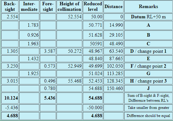
- Booking is the same as the rise and fall method for back, intermediate and foresight. There are no rise or fall columns, but instead, a height of collimation column.
- The first backsight reading (staff on datum, benchmark or RL staff) is added to the first RL that gives the height of collimation.
- The next staff reading is entered In the appropriate column but on a new line. The RL for the station is found by subtracting the staff reading from the height of collimation.
- The height of collimation only changes when the level is moved to a new location. The new height of collimation is found by adding the backsight to the RL at the change point.
- Please note there is no check on the accuracy of intermediate RL's and errors could go undetected.
It may take a bit longer to complete the rise and fall process, but a check is carried out on entries in all columns. With the height of the collimation process, the RLs are easier to calculate, but errors of intermediate RL's can go undetected. For this purpose, you should use the method of rise and fall for all grading exercises.
Closed and open traverse
Always commence and finish a level run on a datum, benchmark or known RL. This is what is known as a closed level traverse and will enable you to check the level run.
A pictorial representation of the three types of traverses are shown here.
Closed level traverse
Start and finish level runs on a datum, benchmark or established RL. This is what is known as a traverse of a closed level, which will allow you to verify the closed level run and carry out reduction using rise and fall method or height of plane collimation.
Misclosure, the sum of the run errors, in millimetre ≤24 × √km
Closed loop level traverse
The series of level runs from a known datum or RL back to a known datum or RL.
Misclosure in millimetre ≤24 × √km
Open level traverse
The series of level runs from a known datum or RL. This must be avoided as there are no checks on misreadings.
Application of closed-level run
You must perform a reduction in a closed level run with an established benchmark.
- You must use at least two different stations for taking the levels.
- You must note levels at a minimum of 8 different points and return to original benchmark.
- You will note the backsights and foresights and the transfer between the levelling stations.
- You will perform the calculations and document the levelling by the following two methods:
- Rise and fall method
- Height of collimation method
A staff reading represents the distance the staff station lies below the horizontal line of sight of the instrument. Rises or falls are deduced by taking the arithmetic difference between each staff reading and the one following it, if observed from the same instrument set-up. This will have been recorded on the next line, immediately below, or below and to the right.
The rise or fall from the first to the second staff station is recorded on the same line as the second staff reading. This is repeated for every consecutive pair of readings taken from the same set-up. Note that the "back" and "fore" readings on a change point line are not compared with each other.
To check the arithmetic of the reduction and accuracy of the entry the following steps apply:
- The "back", “fore”, “rise” and “fall” columns on each page are individually totalled.
- The difference between the total of backsights and total of foresights should equal the difference between the total of rises and total of falls.
- After this check, the reduced levels of all the staff stations are deduced by applying the rise or fall to the reduced level of the previous station. Work successively from top to bottom of the page.
Finally, the difference between the first RL and the last RL should equal the already balanced differences between total backsights and total foresights and total rises and falls. If there are no compensating errors this gives a complete check on the reduction. The column total and check differences should be recorded at the bottom of each page. If the last staff station is a benchmark, this also gives a check.
For calculating accurate staff readings to enable a specific reduced level (RL) set-out, a level filed book, or a level book must be used. As described previously, there are two methods for decreasing amounts, namely:
- the height of instrument method
- the rise and fall method
Height of the instrument method
A level reading is taken at the site datum point and this is added to the datum value to create a new value called the ‘height of instrument’ (HI).
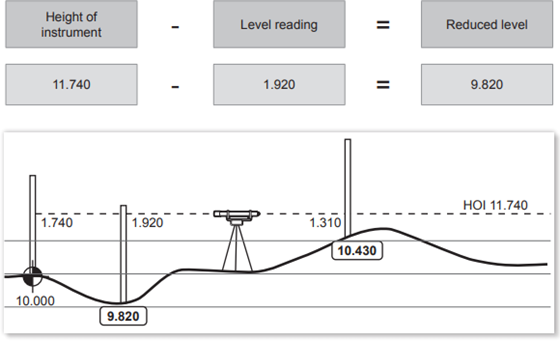
Note: The reduced level of the datum point is always the datum value, for example:
11.740 – 1.740 = 10.000
When the reduced levels for level readings are calculated, they are recorded in the field book.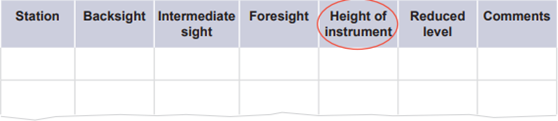
There is a new column in this table – Height of instrument. This column will contain the height of the instrument at each station.
Rise and fall method
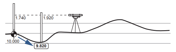
Rather than taking each level reading based on a reference level, the rise and fall method moves from one reading to the next.
This method starts at a known point (the datum), so the first reduced level is equal to this datum value.
If the next level reading is larger than the preceding reading, then this represents a fall, because the level is lower than the previous level. This is shown below, where the reading is 1.920, which is larger than 1.740, and hence this elevation is lower than the datum.
If the next reading is smaller, such as the case in the following diagram, the elevation is higher, so there is a rise.
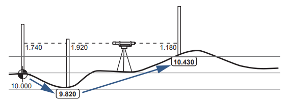
By calculating the difference between each successive reading, the reduced levels can be identified and this is called the rise and fall method.
The readings and the reduced levels are recorded in a field book.
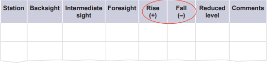
There are two new columns in this table – Rise (+) and Fall (–). These columns represent the amount and direction of difference between the reading and the previous reading.
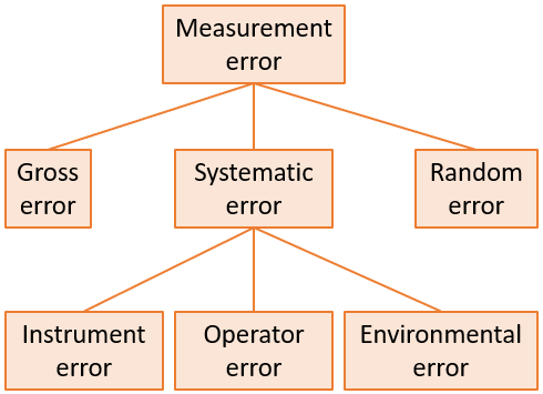
There are many potential sources of errors when making measurements, and this includes the measurement of distances when surveying.
Gross errors are a result of human blunders, for example recording a value with some digits reversed. These errors should be easy to detect when reviewing measurement results.
Random errors are a result of a sudden change in measurement conditions. These could, for example, be environmental effects on the instrument or noise or tiredness affecting the operator.
Systematic errors fall into three categories and these are discussed in more detail below.
A pictorial representation of error types is shown here.
 |
|
|
|
Instrument errors may occur due to one or more of the following:
|
Operator errors may occur due to one or more of the following:
|
Environmental errors occur due to external conditions affecting measuring devices. This could include:
|


Errors in measurements due to site characteristics
Errors in measurements during set-out may be specific to a particular site because of its characteristics. For example, these may include:
- position of the site
- shape of the site
- size of the site
- site personnel
Measurements are important when designing a building or project. Some variables will influence measurements on particular sites, for example:
- slopes
- wind
- vegetation
- other impediments
Minimising errors
The following are methods that surveyors can employ to minimise errors in their measurements:
- Equalise the lengths of the backsight and foresight distances to eliminate residual collimation error of an instrument
- Ensure the staff is vertical by either fitting a staff bubble to the staff or, during measurement, swaying the staff backwards and forwards in the direction of the level until a minimum reading is obtained
- Reducing the length of each sight to minimise errors in reading the staff
- Setting the staff on firm ground, pushing the tripod legs well into the ground, and avoiding excessive movement of the instrument eliminates the error caused by an unstable instrument
- Keeping readings at least one metre above the ground reduces the error due to refraction caused by warm air
- Bringing the crosshairs into sharp focus using the eyepiece-focussing screw eliminates parallax errors