
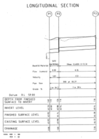
Longitudinal sections are designed to show a pipeline in sections, displaying the grades, chainage, and other details. These show what the reduced level is at the chainage or distances taken in the survey readings, and where the pipes or drains will be in relation to these levels.
Drainage longitudinal sections shall be provided for all proposed stormwater drainage lines. They shall be drawn to Australian Height Datum (AHD) at the same horizontal scale as the plan view and with a vertical exaggeration of five, oriented with chainages running from left to right and shall include the following:
- existing and design surface profile
- existing and design surface levels
- existing drainage pipelines
- utility services
- design pit and pipe profiles
- chainages along pipe centreline
- proposed pipe grade, size, and class
- design flow and velocity
- drainage structure definition
- junction and node identification
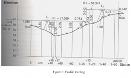
Profile levelling
A common surveyor task of running levels and vertical distance measurement is profile levelling. The results are plotted as a profile, which is a drawing that depicts a vertical cross-section. Several structures, including buildings, need profiles for design and construction. Essentially, profile levelling is the method of assessing the elevation of points on the ground along a continuous line at often uniform intervals.
For profile levelling, you will need the following equipment.
- tripod
- staff bubble
- chain or Tape
- dumpy level
- levelling staff
Longitudinal section levelling
Profile levelling is very similar to benchmark levelling except that backsight measurements are made to determine the height of the instrument (HI). These back sight rod reading are called rod shots and may be required multiple times depending on the number of instrument positions needed.
Creating a profile
The profile drawing is essentially a graph that plots elevations on the vertical axis as a function of stations on the horizontal axis. The profile data from the field book is plotted on a gridded sheet called profile paper. A proper title block is needed for all profile drawings, and both axes must be fully labelled with stations and their elevations.
In most cases, the vertical or elevation scale is exaggerated, or ‘stretched' in contrast to the horizontal scale. This is done to make the change in elevation more obvious. The vertical scale, for example, may be ten times larger. It is not necessary for the horizontal line at the bottom of the profile to begin at zero elevation.
‘Grade’ is a term used to identify the level of the earth at a specified location. The terms ‘above grade’ and ‘below grade’ can be used respectively to describe the part of a structure above or below the building’s ground level. ‘Level,’ on the other hand, is the height of a specific point relative to another. It is used in surveying to determine the elevation of a point relative to an arbitrary horizontal plane of reference from which all vertical dimensions are measured.
Establishing a site’s grade is important because it gives the construction crew an idea on how to prepare the site for construction. When the grade is established, the construction crew will use said grade to prepare the site so that water flows away from the foundation of the building. Since levelling involves determining the height of a specific point relative to another, surveyors can determine how the earth around the ground level of the construction site should be cleared and, ultimately, sloped away from the foundation to divert water.
Longitudinal sections also give us the required levels and clearances. The Plumbing Code of Australia shows that these must be in accord with AS/NZS 3500 for the plumbing industry, which consists of the following:
- AS/NZS 3500.1, Water Services;
- AS/NZS 3500.2, Sanitary Plumbing and drainage;
- AS/NZS 3500.3 Stormwater; and
- AS/NZS 3500.4, Heated water systems.
In particular, you will refer to AS/NZS 3500.2 and 3500.3 to give you the grades necessary for underground pipework. When designing drainage and pipelines, you need to refer to these standards to ensure that all specified tolerances are met.
In the drawing of plans, once you have the reduced levels, you can then design the drainage or pipework according to the AS/NZS 3500 to ensure that the grades are correct for the distances involved. These are shown in the longitudinal sections.
You have two sections included in the one drawing that outline the following details:
- depth from finished surface to invert (lower level of drain)
- invert level
- finished surface level
- existing surface level
- chainage
- backfill material
- flow
- velocity
- pipe size
- grade
You will also notice that the scales are:
- horizontal 1: 100
- vertical 1: 50
Tolerances
Tolerances are acceptable degrees of deviation from the required specification in a plan. Tolerances are determined by many factors, including the measuring equipment used, the type of soil in the site, and the materials used in the project. In determining levels and clearances, grades and distances must be measured within acceptable tolerance levels. Acceptable tolerance levels are usually indicated in the construction plans and must be followed.
One of the most important aspects is deciding how large the tolerances can be without affecting other variables or the process's outcome. This can be achieved by the implementation of scientific concepts, engineering skills, and professional experience. To examine the effects of tolerances, experimental investigation is very useful: design of tests, formal engineering assessments, and so on.
By itself, a strong set of engineering tolerances in a specification does not guarantee that such tolerances will be met. To create a commodity (or run a system), there must be some difference in input and output. Both measurements include measurement error and statistical uncertainty. The tails of calculated values in a normal distribution may extend well beyond plus and minus three standard deviations from the process average. It is probable that a large portion of one (or both) tails may stretch beyond the tolerance.
Device, material, and product process capability must be compliant with specified engineering tolerances. Process controls must be in place, and a quality management system such as Complete Quality Management must be in place to keep actual output within the desired tolerances. A process capability index indicates the relationship between tolerances and actual calculated output.
Application for determining levels
You can set-out a grid on a sloping block to work out the cut and fill volumes. You can then take levels at each intersection of the grid and note these. You can then determine the cut and fill line for the block and then calculate the volume to cut from the block and the volume needed for fill. You need to show how you arrived at these calculations.
Calculations and expression of grades
The AS/NZS 3500 gives us the required minimums for grades of pipework. These are determined to give flow rates necessary to self-clear the piping or drainage systems. The grades will vary according to pipe size, and whether it is sanitary or stormwater systems. Both are covered in this Australian standard. It specifies the allowed tolerances for these systems.
Grades can be expressed in 3 ways:
- angles
- percentages
- run ratios
Angles specify the grades in degrees for the pipework and is the angle between the pipework and a horizontal.
A grade shown as a percentage is how much the level rises, divided by the run length and multiplied by 100%.
The ratio grade shows a normalised level rise as a ratio to the run length.
The most common ways to express grades are as a percentage or a ratio.
The following example shows how each of these work. This diagram is not to scale and is used to illustrate the example.
Assume that over a 50 m horizontal length, a pipe’s level changes 3.5 m. You could use Pythagoras’ theorem, covered earlier, to calculate the pipe length (50.1 m).

To find the grade as an angle, use the arctan (tan-1) function on a calculator. Arctan (3.5/50) gives 4°.
The percentage can be found by dividing 3.5 by 50 and multiplying by 100%. This gives 7%.
For the ratio, we need to find the horizontal length that would give a 1 m rise. We have 50 m for a 3.5 m rise, so 14.3 m for a 1 m rise. The ratio is 1:14.3.
In summary, the grade can be gives as 4°, 7% or 1:14.3.
In AS/NZS 5300.2 the following minimum grades are mentioned:
- A drain with a nominal diameter of 65 mm must have a minimum grade of 2.50% or a ratio of 1 in 40.
- A drain with a nominal diameter of 100 mm must have a minimum grade of 1.65% or a ratio of 1 in 60.
Elevation grade calculator
An elevation grade calculator can help you calculate the grade and convert it to different forms, as discussed earlier. Enter the values you know, and the calculator will do the calculation and conversion. There are several easy to use online calculators available. Refer to the Additional resources section.
What is the concept of elevation grade?
The elevation grade of a site is its steepness. It is also called the angle of inclination, grade or slope. The elevation grade may refer to the change in elevation between two points on a site, how the grade has changed over time or the different grades across the site. Land surveyors and engineers with appropriate tools and training can provide documented evidence for elevation.
The reference level for elevation is usually the average sea level. Recall the Australian Height Datum discussion in previous modules.
Why do you need to know the elevation grade of a specific terrain?
Knowing the elevation grades of a site is important. We have already looked at the need for setting the grade to plan drainage. Here are some further examples of the significance and benefits of understanding a specific area's grade:
- In road construction, understanding the elevation grades during the design and construction of roads helps make the road safer. For very steep terrain, roads can be laid out in a zig-zag pattern to reduce the grade of the road. Engineers may implement cut and fill procedures to reduce the slope on less steep terrain. Knowing about the grade will also help control any water flow across the road during rain events with careful cambering and curbing.
- Retaining walls are used to reduce erosion and provide level areas. Elevation grade information is important to determine the amount of earth that needs to be supported and the design requirements for the wall.
- Building design is affected by the grade of the site. Larger footings or foundations are required for buildings on steeper land.
- Analysing water flow across a site requires elevation grade information. Deciding how land may be irrigated is based on the land’s gradient. Grade information is also necessary to plan water erosion mitigation.
How can you work out the grade and angle of elevation?
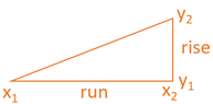
The grade of the terrain is measured in the same way as the slope of a line is calculated. The coordinates of a line's endpoints are required to measure its slope. The slope is proportional to the quotient of the change in y values divided by the change in x values. The change in y values can be found by subtracting the smaller value from the larger value (y2-y1), and similarly for the x values. It looks like this as an equation:
slope= (y_2-y_1)/(x_2-x_1 )
These changes in x and y values have nicknames in the mathematical community and you may remember these from school. Since the transition in y values is along the vertical axis, we call it "rise." The change in x values, on the other hand, is referred to as a "run” ratio because it follows the horizontal axis. This relationship yields the well-known equation "slope equals rise over run," which you might have heard before.
slope= rise/run
The x and y values and the naming conventions are shown in this diagram.
Trigonometry can be applied to determine the slope angle. This is detailed in an earlier section, but summarised here. Angles that rise from the horizontal line are called "angles of elevation," while those that fall are called "angles of declination."
The arctan function can be used to find this angle. Arctan function is the inverse of the tangent (tan) function. It looks like this in equation form:
slope angle=arctan(rise/run)
This function is available on scientific calculators, smartphone calculator apps or you can use an online calculator.
Grades can also be presented as a percentage. Multiply the ratio value by 100. A grade of 100% implies that the rise and run of the slope are equal, which gives an angle of elevation of 45°. The equation is:
percentage slope= rise/run ×100%
Understanding the grade values at various elevations
It is worthwhile becoming familiar with the type of landform these values represent. We said earlier that a slope of 1 is equivalent to 100% and 45°. This is the slope of a steep mountain. Slopes above 10° (18%) are significant and considered a challenging building site.
How to find out what the "rise" and "run" ratios are
Using a measuring tape, you can measure the "run" or horizontal distance. To get an accurate measurement, you will need to pull the tape taut and keep it level. The vertical distance, on the other hand, can be measured using optical devices such as a surveyor's transit and a leveling rod. An inbuilt telescope in a surveyor's transit may be rotated laterally or vertically over a tripod. A reading can be obtained by concentrating it on the leveling rod (which resembles a large ruler). The height between the leveling rod and the transit can then be determined using this reading. When used with a leveling pole, a surveyor's transit has distinctive markings on its view that allow it to calculate horizontal distances.
You may also use a clinometer, which provides the angle of elevation between two points directly. A clinometer is a small telescope with a protractor on one side. Other, more advanced digital devices will now assist in evaluating the slope of a given surface. When you lay your smartphone on a slope, it will accurately provide you with the slope if it is fitted with appropriate hardware such as gyroscopic sensors.
When installing drainage or pipelines we need to consider batter levels for the following areas:
- work health and safety
- erosion control
For work health and safety, we may use batters to control the risk of collapsing trenches causing injury or death.
One fairly simple way of controlling the risk of ground collapse is to bench or batter the excavation walls. An excavated slope is safe when the ground is stable. It is stable when the slope does not flatten when left for a considerable period, there is no movement of material down the slope, and the toe of the slope remains in the same place.
If excavation work is planned to be carried out without positive ground support (that is, shoring), the continuing safety of the excavation will depend on the conditions arising during construction. If the conditions during construction are not as expected, or if conditions change during the course of the work (e.g. different soils, heavy rain/flooding), action should be taken immediately to protect workers, other persons and property. Implement appropriate control measures such as temporarily suspending work until the ground is stable or, if necessary, providing positive ground support.
Benching and battering
Benching is the creation of a series of steps in the vertical wall of an excavation to reduce the wall height and ensure stability. Benching is a method of preventing collapse by excavating the sides of an excavation to form one or more horizontal levels or steps with vertical surfaces between levels.
Battering is where the wall of an excavation is sloped back to a predetermined angle to ensure stability. Battering prevents ground collapse by cutting the excavated face back to a safe slope. Battering should commence from the bottom of the excavation and in some circumstances, it may be appropriate to use a combination of the two methods on an excavation.
Benching and battering of excavation walls can minimise the risk of soil or rock slipping onto the excavation. Control measures should be designed by a competent person (e.g. geotechnical engineer) and be relative to the soil type, the moisture content of the soil, the planned height of the excavated face and any surcharge loads acting on the excavated face.
Risks of collapse
It is unnecessary to bench or batter the face of excavations that a competent person determines are in stable rock or has assessed that there is no risk of collapse. When benching or battering the walls of an excavation, an angle of repose of 45 degrees should not be exceeded unless designed by a competent person and certified in writing.
Benches should be wide enough to stabilise the slopes and to prevent material from the top falling to the working area. They should also be sloped to reduce the possibility of water scouring. The size and type of any earthmoving machinery to be used and any related haul routes should be considered when designing the face slopes and widths of benches.
In working out the levels of the batters of benches, it is necessary to have obtained the levels of the base of the trench or where it will be. This can be done beforehand by taking the reduced levels of the existing ground level and then calculating the finished level for the base of the trench using the grade required for the piping.
Stormwater applications
The other aspect of battering is when it is used for stormwater applications. It may be necessary to calculate the runoff for a certain area, and the slope of the batter will determine the erosion factor. This will also determine what type or thickness of covering that needs to be applied to the batter to ensure that erosion is kept under control. This is particularly used along roadways or large commercial projects.
Calculation of both types of batter needs to be accurate, as WHS will be affected if there is negligence for the first instance, and the environment could be affected by the second.
Batter boards
Batter boards (or battre boards) are temporary frames positioned at specific elevations outside the corners of a planned base. The pattern lines (construction twine) are used to show the foundation's limits (edges and corners) on these batter boards.
The surveyor's most common and challenging job is to reference corners and boundaries for the proposed building's design. A batter board is used for this purpose. A key component is a nail that is used to keep string straight from one batter board to the next. Since the batter board is laid at a 1.5-metre offset from the planned structure, the string may be removed briefly during construction while the board stays in position to be used again.
Calculating batter levels from grades and distances
Wooden batter boards are placed a safe distance away from the corners of the designed structure. They assist in setting lines, grades, and distances. If the building process causes a loss of line, grades, or distances, batter boards can be used to re-establish them. If a surveyor is searching for corners, measurements should be taken from a longer baseline rather than a shorter baseline for greater precision.
A series of batter boards are positioned across the grades, lines, and distances at uniform intervals after the ground is opened to a depth slightly deeper than that needed.
- First and foremost, the building's location must be determined. To show orientation and distances, the approximate location can be marked with sand or spray paint.
- The first three stakes are then mounted at 100 centimetres from the building's corners. The stakes should be driven about 50 centimetres into the dirt.
- After that, additional stakes should be mounted parallel to the building's sides.
- The stakes should be perpendicular to each other.
- The stakes should be mounted approximately 50 centimetres above the uppermost edge of the building's base.
- The upper edge of the boards should be level with the stakes' markings.
- The boards must be fixed horizontally and at the same height between the stakes.
- For each corner of the house, the batter boards must be positioned in the same manner.
- A surveying office uses nails on the batter boards to mark the house corners with millimetre accuracy for the fine stake-out.
Setting up of batter boards
Before construction can commence, batter boards must be set up to map out the exact location of the building on the plot. The site plans are used to determine the exact location and height of the building.
The rough stake-out, which points out the location of the work to be done at the site, must be completed before the batter board installation can be completed.
Batter boards and stakeouts
The batter boards are mounted as part of the fine set-out. After the excavation for the building is complete, fine stakeouts are undertaken. The area is marked with nails connected by string for this reason. The batter boards indicate where the building will be built and how high the foundation will be set.
Batter board installation and building permit
The building permit may require an inspection after the batter board installation. The building authority representative will verify the proposed location and height of the building according to the permit documents. The batter boards then serve a legal function as they provide evidence of the building approval. It is therefore important that batterboards are not removed prematurely.
String positioning and stakeouts
Since building construction involves strict tolerances of just a few millimetres, it is often preferred to employ a surveying professional to measure the corner points of a batter board installation. The measurement is usually done with a tacheometer, particularly on large and complex construction sites.
Three stakes are positioned one meter from the corners of the future building at the start of the batter board installation process. Strings are attached to nails that extend from corner to corner after the outer walls have been marked out. The nails should be positioned at the same height as the base stake to show slab height.
You must also conduct construction stakeouts for individual floors of the building for larger buildings and where a high level of precision is needed.
The batter boards and the building's height
To meet building permit and building specifications, the location of a building and also its designed height are important. Batter boards are used to set slab height and care must be taken with measurements to ensure the building is made to the correct height. For complex building design, making use of a professional surveyor is preferred.
Common errors preparing batter boards
Utilising services to prepare batter boards is often preferred, especially if this preparation makes part of the building permit. Otherwise, the builder may hold suitable permits to do the work.
Timber selection is important, so check high quality and sturdy materials are used, not just recycled timber. Also, ensure stakes are driven firmly into the ground to a depth of approximately 500 mm.
It is important to understand the different types of drainage systems. Drainage includes sanitary drainage that takes waste to a sewerage handling system. Stormwater drainage is a separate system designed to collect and direct rainwater and runoff to a suitable outflow.
State and territory authorities have their own Acts and Regulations that reference Australian Standards. For example, a good introduction to drainage system requirements for Victoria is given here
https://www.vba.vic.gov.au/plumbing/registration-licensing/drainage
Sanitary systems need careful design to determine pipe size and gradient (grade) requirements. The type of sanitary connection, frequency of use etc, will determine the flow rate. This, along with whether the system is vented or not, will allow gradients to be determined. An ABCB report gives further details including calculation methods:
file:///C:/Users/97072/Downloads/Report_Sanitary_plumbing_drainage_and_pipe_sizing.pdf
Stormwater design is also required to determine adequate pipe size and gradient. The VBA provides a useful technical information sheet that refers to applicable standards and shows how to perform stormwater drain sizing and roof downpipe placement calculations.
This sheet shows that the minimum gradient for stormwater drains is specified in AS/NZ 3500.3 and summarises that for pipes with a nominal diameter 90, 100 and 150 mm is 1:100, or an angle of 0.6°.
Longitudinal section drawings need to be completed to show the planned drainage system. The section should show drain and pipe details. Information from Melbourne Water shows the type of information that a section drawing will show and gives an example.
https://www.melbournewater.com.au/media/646/download
Drawing requirements
There will be a number of technical details that will be required when drawing longitudinal sections. These may be set by local council or authority and include title blocks, correct use of standard symbols and may state a scale and print size. A site plan will be needed to show how the project fits to nearby streets and features related to the drainage or pipework.
Longitudinal section
The longitudinal section gives the relative height of different parts of the drainage system. The following are some items that must be included:[25]
- chainages, commencing at zero at the downstream end
- surface levels
- invert levels
- datum to the Australian Height Datum (AHD)
- grade of the drain
- class of pipe
- bedding and backfill
- access hole details
Refer to this example section to see how these items are represented.
Example_Longitudinal_Section.pdf
Scale
The drawing scale for longitudinal sections should be one of the following:
| Drawing type | Scale |
| longitudinal section |
1:2500 (horiz) 1:250 (vert) 1:1000(horiz) 1:100 (vert) 1:500 (horiz) 1:50 (vert preferred scale) |
Note the difference in scale in the vertical direction to exaggerate the fall and help the reader understand the design. Refer to the example Longitudinal Section to see this difference.
Standards
Several different Australian Standards may apply to your construction.
| Standard | Description |
| AS/NZS 2032-2006 | Code of Practice for installation of UPCV pipe systems |
| AS/NZ 2033-2008 | Installation of polyethene pipe systems |
| AS 2566.2-2002 | Buried flexible pipelines- Installation |
| AS 3690-2009 | Installation of ABS pipe systems |
| AS3725-2007 | Design for installation of buried concrete pipes |
| AS 4058-2007 | Pre-cast concrete pipes (pressure and non-pressure |
| AS 4139-2003 | Fibre-reinforced concrete pipes and fittings |
Functional design
The functional design contains design details such as the calculation of levels and pipe sizes and connection details. This is where the basis for calculations are stated, and
the results of the calculations for pipe size and grade are stated.
Application of pipeline run
On the building site that you set-out, you will take levels for the drainage line to the sewer junction. You will need to determine the level at the start of the drainage line, and
the level of the sewer junction.
The longitudinal sections need to meet the local authority requirements for approval.