This Modelling topic delves into the fundamental aspects of creating visually captivating 3D models and essential skills for any aspiring animator.
Whether crafting intricate environments, lifelike models, or intricate props, mastering the art of model and texture creation is critical to bringing your digital creations to life.
As you progress through this topic, you will learn the fundamental skills required to model, followed by a topic on how to texture various objects successfully.
Subtopics that you will explore
Work through four key Modelling subtopics. These subtopics will offer valuable insights, tutorials, and essential techniques to foster your animation skills. As you progress, you will find that some of these subtopics will be paired with a corresponding subtopic outlining the specific system steps required for learning tasks and assessment preparation.
The main subtopics include:
- Hard surface modelling
- Exploring Basic Modelling
- Basic Modelling Process
- Symmetrical Modelling
- Symmetrical Modelling process
- UV Mapping Process
- Creating New UVs Process.
Frequently used modelling tools and operations in Autodesk Maya
In the following playlist, find out about some of the main modelling tools and processes used while modelling in Autodesk Maya.
Use these seven videos as a quick access reference for tools and UI interaction in Autodesk Maya, from the main modelling marking menus, which allow fast access to the most frequently used modelling tools and operations, to some of the most used and useful modelling tools in the Autodesk Maya toolkit.
Learning tasks that will support your skills in digital production have been outlined in the following table.
Practice
Put your skills into practice and extend your knowledge
As you work through the learning, you will encounter a series of learning tasks that you must complete within the Modelling topic and showcase on the discussion forums.
Keep an eye out for the PRACTICE boxes as you progress through the learning process to identify the learning tasks, resources, and instructions for what you must do. They also house the information regarding the specific subtopics and how long you must allocate for these tasks. This has been briefly outlined below.
Remember, there will be learning tasks that you will need to complete that link directly to your assessment, so please read through them carefully.
| Learning task # | Learning Task Name | Duration (Hours) | |
|---|---|---|---|
| 1 | Model a dining chair | 4 |
|
| 2 | Design and model a symmetrical spacecraft | 8 |
|
| 3 | Design and build additional 3D models | 5 |
|
| 4 | UV the provided ballpeen hammer model | 4 |
|
| 5 | Create a UV layout for your spacecraft model | 6 |
|

Feedback and support are woven through the learning tasks as you complete them. Reach out if you have any questions about what to do!
This topic will take you through hard surface modelling. Take your time and read the material carefully to help support you with the relevant learning tasks.
What is hard surface modelling?
To put it simply, in modelling terms, hard surfaces are any non-living objects with static surfaces that do not deform if they are animated. Most manmade objects would be categorised as hard surface objects. Some typical examples of hard surfaces include the following:
- weapons
- machinery
- vehicles
- buildings
- and any natural hard surfaces like rocks, etc.
Characters like robots and Lego figures could also be thought of as hard surface models.
The following images give you some visual examples of hard surface objects.
![[ADD IMAGE'S ALT TEXT]](/sites/default/files/Collage%20Hard%20Surface%20Objects.jpg)
Guidelines
Here are a few guidelines to keep in mind while modelling. These will help to keep your models clean and lead to a much more pleasant modelling experience.
1 - When modelling, use the fewest number of control vertices possible
Try to model your objects using the most basic shapes; only add more detail to the mesh when you need to.
When starting to model a shape, try to use the fewest number of vertices you can. Start by creating the basic shape of your model first and only add more vertices to the model if you absolutely must. This will make it far easier to change and adjust your object's overall shape with the least difficulty later.
An added benefit of keeping the model as light as possible is that it will be far less taxing on your computer system and render much more quickly than a model with a lot of unnecessary topological detail.
2 - Evenly space edge loops
Any edge loops added to your models should be evenly spaced so that each loop evenly divides the curvature of a shape. This will ensure that your model’s mesh is smooth across its surface and will help create a predictable smoothness.
3 - Avoid having triangles or N-Gons in your model
When modelling, try to use only quads or four-sided polygons. This is because triangles and N-Gons can subdivide and deform unpredictably, causing unwanted creasing and wrinkling in your smoothed model.
4- Isolate detail in your model
If you have areas of a model that require more detailed shapes, you need to isolate and redirect the flow of faces and loops to only that area. This is because extra edges or topological detail in other areas of the model will interfere with the overall shape and form, resulting in undesired changes to the forms you have modelled once the mesh is smoothed.
An excellent example of this is in the hands of a character, where we need more topological detail to create the fingers of the hand, but we also don't want the added edges to flow up the arm and into the rest of the model. You can see that the extra loops of the fingers are redirected into a single vertex, which helps reduce the number of loops so they don't flow through the rest of the model.
Check out the example of the hands of a character below.
![[ADD IMAGE'S ALT TEXT]](/sites/default/files/Isolated%20Hand.jpg)
Check edge flow and curvature
While working, use multiple camera angles to check edge flow and curvature. It is essential to switch between various camera angles to see the shape you are modelling from all angles. It is very easy to model a shape from only one view and then switch to a different angle only to find that the curvature of the shape from the new angle could be more cohesive and uneven.
Now that you have learnt hard surfaces and guidelines in modelling,it's time to explore basic modelling. Throughout this subtopic, you will familiarise yourself with the various processes required to undertake a basic modelling task.
At the end of this subtopic, you will be given a learning task to practice your modelling skills.
Get started by modelling some simpler, everyday and complex surface objects. While doing so, get more familiar with the Maya modelling workflow and learn some of the many modelling tools available to the modeller along the way.
As with most things in animation, it will be very important for you to practise the techniques and steps shown as much as possible to be sufficiently familiar with the tools and process of modelling and texturing.
After this course, you will be assessed on your modelling and texturing technique, planning and execution through the submission of a completed.
Modelling: where to begin?
To begin modelling a shape, you will need to choose from the primitives that are available in Maya. Each primitive is created slightly differently, affecting how its topology is structured. This, in turn, will affect how easy it is for the modeller to make specific shapes using the polygon primitives as a base starting point. Choosing which polygon primitive you should use to build your model is the first step when starting to model an object.
The following image is an example of the primitives that are available in Maya.
![[ADD IMAGE'S ALT TEXT]](/sites/default/files/Maya%20Primitives.png)
Choosing the suitable primitive to begin modelling your object will influence how straightforward the modelling process will be because each primitive has a slightly different topology.
You should begin by looking at the object you want to model and analyse its basic shape; which of the Maya polygon primitives most closely resemble the object? Sometimes, this will be an easy task. For example, the basic shape of a pen or pencil looks most like a cylinder, so it makes sense to begin your model using the polygon cylinder primitive. More complex shapes can sometimes be more challenging to identify.
A standard Lego brick, for example, is just a cube scaled into a rectangular shape with cylinders for the studs. The image below illustrates a standard Lego brick, highlighting the primitives used to create it.
![[ADD IMAGE'S ALT TEXT]](/sites/default/files/Lego%20Brick.png)
Modelling from reference
When modelling objects in 3D, it is essential to use a reference or references to create an accurate 3D version of the object or character you are trying to model.
Approaches to take
There are a couple of different approaches to using reference when modelling.
Reference materials organically
The first approach is to use the reference material organically and more as a loose guide where you look at the reference material. This will help guide your modelling choices, but the model you create is not an exact duplicate of the reference.
Targeted and technical approach
There is, then, the very targeted and technical approach where you create several reference images from two or more angles of an object, which show the object as several different elevations, for example, front, back and side views. These images are then used in Maya as a physical reference that guides where shapes and curves flow, creating a relatively exact 3D copy of the required model.
This approach is used when you need a specific outcome, like modelling a particular car model or having been given a character design to model in 3D.
In the example below, you can see the various angles of an object.
![[ADD IMAGE'S ALT TEXT]](/sites/default/files/Angle%20Views%20in%20Maya.png)
This subtopic will take you through the basic modelling process. If at any point you need to refer to the steps, select this subtopic in your navigation bar to take you back.
Read the steps below that make up the process and considerations of modelling a basic dining chair in Maya.
Gather reference material
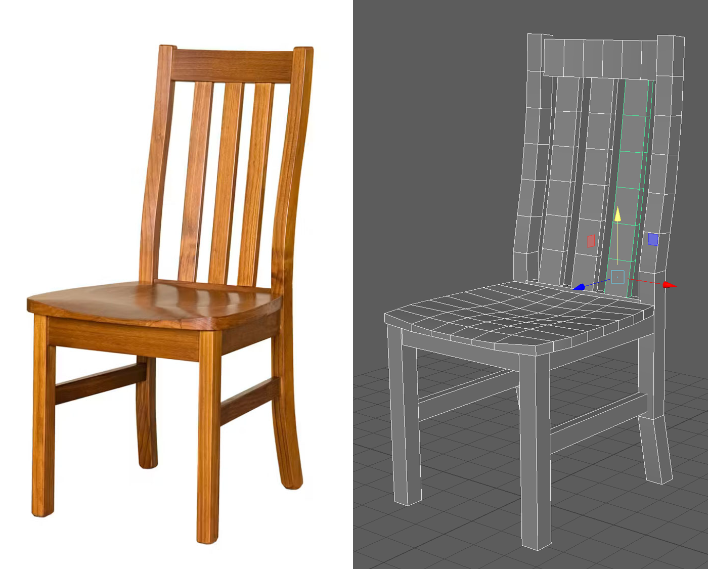
As discussed earlier, the first step in modelling any object is to get good reference material for the required object. Sometimes, it isn't easy to get a reference that shows an object from all sides and angles, which would help you to see exactly how a model should be put together. Still, you can analyse an image and decide the missing detail and how you will fill in that missing information.
Your reference material should give you exactly what you need when you source it.
For example, this reference material provides the user with most of what is required to go ahead and start building a model. Still, it does not implicitly show the exact angles of the chair back or the exact location and makeup of the carved scalloping detail of the seat.
![[ADD IMAGE'S ALT TEXT]](/sites/default/files/Example%20Wooden%20Chair.jpg)
Regardless of whether the chair needs all the necessary information, filling in the missing information can be quickly decided upon and added to the reference with a few quick sketches and notations. This has been illustrated in the following example.
![[ADD IMAGE'S ALT TEXT]](/sites/default/files/Sketched%20Information.jpg)
Once you have made some decisions about the shapes of the chair that were unclear in the reference, you can go ahead and start the modelling process.
Begin modelling, choose polygon primitive.
Firstly, you will need to decide which polygon primitive to use to model the parts of your chair, which, in this case, is a pretty easy decision.
The chair is made of rectangular parts, so you will use polygon cubes to scale, rotate, and add any mesh detail required to get the curves needed to make a convincing-looking chair.
It doesn't matter which part of the chair you begin modelling first; some modellers might start with the back and front legs, or others might start with the seat.
As you become familiar with Maya, you will find various menus you will need to use while you are modelling. These are called the Marking Menus.
Using the marking menus
Maya makes use of marking menus for virtually all of the processes that are possible within the program. Marking menus are keyboard and mouse button combinations that give the user quick access to the most used tools and processes. Most of the menus are context sensitive, which means that the keyboard and mouse shortcuts mostly stay the same, but depending on what you have selected or what window or editor you are in at the time, the marking menu that is displayed will change. The huge advantage of this is that once you know the basic shortcut combinations, it massively increases your speed and efficiency while working.
Now, look at the basic modelling marking menus:
The modelling marking menus can be accessed by holding the shift key and right mouse button at the same time.
Basic Modelling Marking Menus
- With no selection made, holding shift and the right mouse button will give you access to the Creation marking menu, which contains all the polygon primitives for polygon creation.
![[ADD IMAGE'S ALT TEXT]](/sites/default/files/Basic%20Modelling%20Marking%20Menus%201.png)
- With a polygon object selected, holding shift plus the right mouse button will give you access to the Modelling tools marking menu. The modelling tools marking menu contains a selection of the most commonly used polygon modelling tools.
![[ADD IMAGE'S ALT TEXT]](/sites/default/files/Basic%20Modelling%20Marking%20Menus%202.png)
- If you have a polygon component selected, for example, a Face, Edge or Vert, then holding shift and the right mouse button will give you access to the Component marking menu containing tools specific to the selected component.
![[ADD IMAGE'S ALT TEXT]](https://cms-uped.baseux.com/sites/default/files/Component%20Menus%201.png)
![[ADD IMAGE'S ALT TEXT]](https://cms-uped.baseux.com/sites/default/files/Component%20Menus%202.png)
![[ADD IMAGE'S ALT TEXT]](https://cms-uped.baseux.com/sites/default/files/Component%20Menus%203.png)
Beginning the Model
The steps that are involved in beginning the model have been outlined below.
Step 1: The seat
- Create the seat of the chair using a poly cube.
- Use the translate (W) and scale (R) tools to flatten the shape down into a flat square for the chair's seat.
If you need more resolution in your geometry to get the shape you want for the seat, you can change the number of subdivisions in the inputs section of the attribute editor.
![[ADD IMAGE'S ALT TEXT]](https://cms-uped.baseux.com/sites/default/files/Attribute%20Editor%201.png)
![[ADD IMAGE'S ALT TEXT]](https://cms-uped.baseux.com/sites/default/files/Attribute%20Editor%202.png)
- Adjust the vertices of the front and back of the shape.
You need to adjust the vertices of the front and back of the shape so that the seat is slightly wider at the front than at the back. Remember, you can add more resolution later if required, so focus on getting the shape you need using the lowest possible resolution to begin with.
- Rename the polycube to a more meaningful name like ChairSeat_Geo.
Tip
Less geometry often means fewer issues!
Try to avoid creating any non-planar faces
A non-planar face is a face that has been distorted out of a flat plane by manipulating its vertices.
At all times, try to keep all the individual faces of your polygon mesh flat within the vertices that make up the outer boundaries of each face.
Step 2: Chair features
The following are the steps involved in adding features to the chair, including the:
- front legs
- rear legs.
Front legs
Look at the approach you would take for the front legs of the chair.
For the front legs of the chair:
- use a polygon cube
- translate and scale the leg into position at the front of the chair and stretch the cube out to be a long, thin rectangle that reaches from the underside of the chair down to the grid.
- to scale an object in two axes at a time, you can hold the ctrl key on the keyboard while manipulating one of the scale handles.
Using the ctrl key will exclude the handle you are moving from the scale. So, if you hold ctrl and scale the Y axis, the geometry will scale in the X and Z axes only.
- You can switch from the perspective view to the 4-up view by tapping the spacebar.
To switch back to a particular view:
- move the mouse pointer over the view you want and then tap the spacebar again.
Once you are happy with the front leg of the chair:
- rename the cube, ChairFrontLeg_Geo.
![[ADD IMAGE'S ALT TEXT]](/sites/default/files/Chair%E2%80%99s%20Front%20Leg.png)
- Duplicate the front leg using the duplicate shortcut Ctrl+D.
- Translate the duplicate front leg into position using the orthographic views to help with the positioning of the geometry.
![[ADD IMAGE'S ALT TEXT]](/sites/default/files/Duplicated%20Font%20Leg.png)
Next using the same process:
- create the front seat rail that stretches in between the front legs and supports the front edge of the seat of the chair.
![[ADD IMAGE'S ALT TEXT]](/sites/default/files/Chair%E2%80%99s%20Front%20Seat%20Rail.png)
Rear legs
For the rear legs you need a much longer leg that goes from the ground all the way into the back of the chair. To add the required curves and changes in direction that the piece of the chair forms, you will need to add some extra detail to the mesh. To add the required extra resolution you can use the extrude and insert edge loop tool.
The following step action table illustrates the steps that are involved with using the extrude and edge loop tool.
| Step | Action |
|---|---|
| 1 | Create a duplicate of one of the front legs of the chair. |
| 2 | Translate the duplicate into position at the back of the chair. |
| 3 | Using the extrude tool, first extrude the required extra length at the bottom of the leg, giving it the kick out at the bottom for extra stability. |
| 4 | Again, extrude the top of the leg and create the length of the back of the chair. |
![[ADD IMAGE'S ALT TEXT]](/sites/default/files/Back%20Of%20Chair.png)
Using the insert edge loop tool, you can add five new loops (if you select the option box of the tool, an option window will open where you can choose how many loops to add to the model) to the upper portion of the back of the chair and then using the newly created vertices create the slight curve for the back of the chair that is in the reference material.
![[ADD IMAGE'S ALT TEXT]](https://cms-uped.baseux.com/sites/default/files/Tool%20Settings%20Menu.png)
![[ADD IMAGE'S ALT TEXT]](https://cms-uped.baseux.com/sites/default/files/Side%20View.png)
You then need to:
- duplicate the back leg and use the translate tool to move it into position.
![[ADD IMAGE'S ALT TEXT]](/sites/default/files/Front%20Chair%20View.png)
Chair rails
Next, you will need to:
- create the four side rails and back rail that connect the front and back legs to each other.
![[ADD IMAGE'S ALT TEXT]](/sites/default/files/Front%20View%20Chair.png)
- Create the back top rail and insert more edge loops into the geometry to create a slight curve to the back of the chair.
Remember, for good topology, you need to make sure that the loops are spaced evenly across the shape so that each loop shares the job of smoothing out the curve of the form.
![[ADD IMAGE'S ALT TEXT]](/sites/default/files/Top%20Rail.png)
- Add the back supports that run up and down the back of the chair.
You may want to add some edge loops into this piece so that it matches the curvature of the back of the chair.
- Duplicate the piece when you are happy with the shape.
![[ADD IMAGE'S ALT TEXT]](https://cms-uped.baseux.com/sites/default/files/Three%20Back%20Rails.png)
![[ADD IMAGE'S ALT TEXT]](https://cms-uped.baseux.com/sites/default/files/Duplicated%20Back%20Rails.png)
Adding shape to the Seat using Soft Selection
The seat of the chair needs some scalloped detail in the top surface and extra shape around the edges. To create this extra detail, you need more resolution in your geometry.
![[ADD IMAGE'S ALT TEXT]](https://cms-uped.baseux.com/sites/default/files/Top%20View%20Seat.png)
![[ADD IMAGE'S ALT TEXT]](https://cms-uped.baseux.com/sites/default/files/Top%20Seat%20View%20.png)
- Insert more edge loops and adjust the outer shape of the seat as required.
- Continue to add resolution to the model as required for the shape.
Remember that any added loops should be evenly spaced across the shape so that each component (edges, faces, and verts) shares the job of controlling the overall shape of the model.
Now, with the added resolution, you can use the soft selection tool to add the scalloped shape to the seat of the chair. To use soft selection, with the selection tool enabled, using the hotkey 'B' will toggle between normal and soft selection modes. If you hold down the B key and left mouse click and drag, you can change the size of the soft selection brush.
![[ADD IMAGE'S ALT TEXT]](/sites/default/files/Top%20View%20With%20Soft%20Selection.png)
The soft selection allows you to select and move several vertices simultaneously with a falloff in the selection's influence from the selection's centre to the outer edges. This is especially useful if you are trying to move verts and create a flowing curve in the geometry you are trying to manipulate.
![[ADD IMAGE'S ALT TEXT]](https://cms-uped.baseux.com/sites/default/files/Soft%20Selection.png)
![[ADD IMAGE'S ALT TEXT]](https://cms-uped.baseux.com/sites/default/files/Soft%20Selection%202.png)
Adding Holding edge loops
Looking at the model as it looks now, everything about it is indicative of a 3D model. It is simply far too clean; all the edges are perfectly crisp and sharp. Something that never happens naturally in real-world objects.
To help soften the object in 3D, you need to:
- add a smoothing node to help smooth the geometry and add realism to the model.
But before you add a smooth node to the model:
- add holding edge loops that prevent all the corners of the object from becoming rounded when the smooth is added.
Placing the holding edge loops is essential for the type of smoothing treatment you want your edges to end up with. The closer you place the holding edge loop to the model's edges, the sharper the final shape will be when you add a smooth node to the geometry.
Before working on your model, look at a few examples.
A cube with no holding edges wants to become a sphere when smoothed.
![[ADD IMAGE'S ALT TEXT]](/sites/default/files/Square%20%26%20Sphere%20Primitives.png)
To correct this problem, you need to:
- add more loops around the model to help it to retain its shape when smoothed.
So, add loops that are placed around the edges of a shape, which will help hold the volume in the shape that you want.
A cube with holding edges placed somewhat loosely around the object's edges will retain its cube shape but have slightly rounded edges. Like any natural object, it is much more realistic and helps make your models look less stereotypically 3D.
![[ADD IMAGE'S ALT TEXT]](/sites/default/files/Side%20By%20Side%20Comparison.png)
Adjusting the holding edge loops closer to the model's edges creates a sharper 'look' to the model but still retains some slightly rounded edges that help keep your model from looking too artificial. As seen in the example below.
![[ADD IMAGE'S ALT TEXT]](/sites/default/files/Side%20By%20Side%20Comparison%202.png)
However, with the edge loops further away from the edges of the object, an even more rounded shape is achieved when the model is smoothed.
![[ADD IMAGE'S ALT TEXT]](/sites/default/files/Side%20By%20Side%20Comparison%203.png)
Now that you understand a little more about holding edges and what they are used for:
- go through your model
- add holding edges around all the edges of the parts of the model.
After adding the holding edges, you can use:
- the preview smoothing viewing mode with the shortcut '3' on your keyboard.
Be sure to:
- select the geometry you want to preview smoothly first.
This will enable you to preview what your model would look like if you were to add a smooth node to the model.
![[ADD IMAGE'S ALT TEXT]](/sites/default/files/Completed%20Chair%20Model.png)
To return to normal display smoothness:
- press the '1' key again with the object selected.
Step 3: Final Modelling Steps
At this point, you will have reached the final modelling steps for the dining chair. It would help if you went through your work to make final touches where necessary.
Naming
One of the first things you will need to do in the final stages of modelling is:
- go through all the pieces of your model
- make sure that they are all named meaningfully with no duplicate names.
![[ADD IMAGE'S ALT TEXT]](/sites/default/files/Naming%20Convention%20Examples.png)
It is good to get into the habit of having a set way of naming things into categories in Maya. Some examples of naming conventions and object categories have been illustrated in the following table.
| Object category | Naming convention |
|---|---|
| Geometry item | Objectname_Geo |
| Group item | Objectname_Grp |
| Shader item | Objectname_Shdr |
*These are some examples, and the same system is recommended for each category of objects.
Grouping
One of the final steps in preparing a model for use would be to group the parts of the model together.
- Using the keyboard shortcut Ctrl + G with a selection of parts will group the pieces together.
To select the group of a model:
- select one of the parts and then using the up-arrow key. This will select its group.
![[ADD IMAGE'S ALT TEXT]](/sites/default/files/Grouping%20Model%20Parts.png)
Deleting history
When modelling, all the steps and actions you performed in creating the model are preserved and saved inside the inner code of the model. This is great when modelling because it allows you, the modeller, to review the model and make some minor adjustments retrospectively.
Unfortunately, this creation history adds unnecessary data and complexity to a model that can cause issues in later production steps. That is why once a model is completed, it is standard practice for the modeller to make a final delete history on the object, which removes all the creation information before passing the model on to the next step in production.
![[ADD IMAGE'S ALT TEXT]](/sites/default/files/History%20Of%20Model.jpg)
Steps to delete the history of an object
The step action table below illustrates the steps to delete the history of an object.
| Step | Action |
|---|---|
| 1 | Select the object you want to delete the history of. |
| 2 | Go to Edit>Delete by Type>History (Keyboard shortcut Alt + Shift + D). |
![[ADD IMAGE'S ALT TEXT]](/sites/default/files/Delete%20Menu.png)
Smoothing
After you have deleted the history of an object, you can add a smooth node to the model if you add a smooth before deleting the history on the object. In that case, the smooth node will be deleted along with the creation history, leaving your model permanently smoothed with no way of retrospectively changing the number of smoothing divisions.
The steps for adding the smooth have been illustrated in the following step action table.
Steps to add the smooth
| Step | Action |
|---|---|
| 1 | Select the parts of the model you want to smooth. |
| 2 | Use the marking menu (Shift + Right mouse button). |
| 3 | Select Smooth from the marking menu. |
You can adjust the level of smoothness in the attribute editor by:
- changing the number of divisions for the smooth node.
With divisions set to 0, the model has no smoothing and appears as the base mesh that you initially modelled.
![[ADD IMAGE'S ALT TEXT]](/sites/default/files/Cube%20With%20Division%20Options.jpg)
As you can see in the image below, if you set the divisions to 1, the smooth node will add four quads for each of the faces in your model, resulting in a four-fold increase in the resolution of the geometry.
![[ADD IMAGE'S ALT TEXT]](/sites/default/files/Smoothed%20Cube.png)
If you set the number of divisions to 2 and the number of faces again increases 4 times.
Because the number of divisions for the smooth node is adjustable, it is beneficial when you have highly detailed objects that you want to animate (characters or other highly detailed models) because you can set the resolution of the model to be a low value when you need to manipulate it and move it around the shot. Then, increase its resolution again once the animation is complete, and you want to render the shot at full resolution.
Tip
Keep an eye out for video tutorials throughout the learning. Some will be in a series, while others stand alone.
Watch Geoff take you through the process of modelling a basic dining chair using Maya.
Practice
Task 1: Model a dining chair.
This task is the first of your learning tasks. You will need to create your own model dining chair using a reference of your choosing. This will give you firsthand experience with 3D modelling.
What tools or resources do you need?
- Autodesk Maya
- Reference image of a dining chair.
What steps should you take?
4 Hours

Set aside up to to four hours to complete steps 1-9 below. Remember to save your work as you go when using Autodesk Maya.
- Revisit the Basic Modelling subtopic and re-watch the Modelling a basic dining chair video if you need to.
- Pick a clear reference image of a dining chair and open Autodesk Maya.
- Customise marking menus for quick tool access.
- Start with basic shapes to create the chair's main form.
- Use the ‘insert’ edge loop tool to refine the shape and add details.
- Add depth to the chair parts using the extrude tool.
- Create holes or cutouts for details using appropriate tools (if required).
- Ensure rounded features are symmetrical using the circularise tool.
- Use the multi-cut tool for intricate patterns or details.
- Experiment with soft selection for smooth modifications.
What should you do after?
- Take a few moments to reflect on your task and answer the following questions.
- How did your choice of the dining chair reference influence your design decisions?
- How did the final touches improve the look of your model, and are you happy with how it turned out compared to your initial design?
- Share your model of the dining chair to Forum:
- Select your forum thread in Forum: Modelling.
- Select Reply to your first Forum post.
- Enter the words ‘Task 1- Dining Chair’ in your reply.
- Select the Post your response button, then select Edit in your new reply when it shows up.
- Upload your photo(s) or files using the Attachment field.
- Select Save changes to share your coursework to your forum thread.
- Get feedback on this and other learning tasks at the next Live Session – check the Live Session calendar for dates and times. All live sessions are recorded so you can watch them later if you miss a session.
Great work! You have completed your first learning task. Your next task covers Symmetry.

For your next model, you will explore a modelling technique that uses symmetry to complete the model.
An advantage of symmetry is that you must only model one half of the object, which you can duplicate to create the other half.
This technique is beneficial for building any symmetrical model in its overall shape and design. Cars, trucks, weapons, and even characters are roughly symmetrical shapes.
In the following learning task, you'll get to design and model a basic spaceship that uses a symmetrical modelling workflow.
While modelling, you'll explore more modelling tools and continue to use the Extrude tool and Insert Edge Loops tool you have already covered.
This subtopic will guide you through the steps required to complete the symmetrical modelling process. If at any point you need to return to the beginning of this process, select Symmetrical Modelling Process using your navigation bar.
Step 1: Design
To begin the rough spaceship, a symmetrical shape needs to be designed that will form the basis of your simple spaceship model. Since the model is based on a symmetrical workflow the symmetrical drawing tools included with most good digital drawing programmes can be used. For the demonstration, Adobe Photoshop will be used.
Using Photoshop
Begin by:
- creating a new canvas
- selecting the brush tool.
In Photoshop you can enable symmetrical drawing by selecting the symmetrical drawing button at the top of the screen in the tool properties and options area.
The Symmetry button looks like a butterfly:
![[ADD IMAGE'S ALT TEXT]](/sites/default/files/Symmetry%20Button.png)
When you select the button, a list of mirroring options will appear, giving you several options to choose from as to which axis you would like to mirror your drawing across.
![[ADD IMAGE'S ALT TEXT]](/sites/default/files/Symmetry%20Options.png)
Experiment with the different options in your own time. To create the designs, use the vertical axis, allowing the creation of a top-down orthographic view of the basic shape of the ship..
Start by following the steps below.
- Create a basic silhouette of the shape of the ship.
- Play with different combinations of shapes that fit together to make up the overall shape of the ship.
- Think about contrasting different shapes with each other to create an interesting and varied outline of the ship.
- Work quickly without labouring too much with the details of the design.
- Aim to create at least six to 10 different silhouettes of various ship designs.
![[ADD IMAGE'S ALT TEXT]](/sites/default/files/Series%20Spacecraft%20Silhouette.jpg)
Once you have determined the various silhouettes for your ship designs, you will need to shrink them and organise your different designs on the canvas so you can see the designs together on the page.
Consider:
- How do they look?
- Are there any similarities between the designs?
- Did you manage to create a varied selection of different designs?
Once you have made the considerations:
- Select a silhouette that you are happy with.
- On a new layer, start playing with the shapes of the design - try different combinations and different proportions.
When you have a shape that you are happy with:
- create a new layer
- start to work out the details of the ship design using the basic shape as a guide.
![[ADD IMAGE'S ALT TEXT]](/sites/default/files/Outline%20Of%20Spacecraft%20Features.png)
If you have designs that are too similar, come up with a replacement.
Draw your ship from different isometric angles (top, side, rear etc). The angles will help you to better understand the overall shapes of the ship. Use these views of the spacecraft as a reference when modelling the shapes in 3D.
![[ADD IMAGE'S ALT TEXT]](/sites/default/files/Spacecraft%20Angles.jpg)
Step 2: Setup and start modelling in Maya
Once you are happy with your design:
- open Maya
- set your project space
- save a new file called 'SymmetricalModelling_Spacecraft'.
Now, you can begin by preparing reference image planes for the side and top views of your spacecraft to assist you in the modelling process.
Setting up reference planes for modelling
Creating reference planes in Maya
To create an image plane in Maya that you can use as reference while modelling, go to:
- Create>Free Image Plane
This will create an image plane as the origin of your scene. You can duplicate this image plane by:
- pressing G on the keyboard (the G keyboard shortcut duplicates the last action).
![[ADD IMAGE'S ALT TEXT]](/sites/default/files/Create%20Planes.png)
Now that you have two image planes in your scene:
- select them in the outliner
- rename them to 'TopView' and 'SideView', respectively.
![[ADD IMAGE'S ALT TEXT]](/sites/default/files/View%20Options.png)
Next for your image plane, in the attribute editor:
- select the Image Name folder icon
- select the view image of the object you want to model.
![[ADD IMAGE'S ALT TEXT]](/sites/default/files/Attribute%20Editor.png)
The reference images for your model should be saved in the 'Sourceimages' folder of your Maya project filing system.
![[ADD IMAGE'S ALT TEXT]](/sites/default/files/Filing%20System.png)
If you cannot see the image on your image plane, then you will need to enable textures in your display view. To enable textures:
- select the ‘6’ key on your keyboard or
- select the enable texture view button at the top of the view port window.
![[ADD IMAGE'S ALT TEXT]](/sites/default/files/Texture%20View%20Button.png)
![[ADD IMAGE'S ALT TEXT]](/sites/default/files/Symmetrical%20Image%20Plane.png)
Now that you have an image showing in your image plane:
- push the plane off away from the origin point of your scene.
![[ADD IMAGE'S ALT TEXT]](/sites/default/files/Separated%20Image%20Planes.png)
A handy adjustment you can make to an image plane under the Alpha Gain attribute in the Attribute Editor lets you control the transparency of the image plane. Using this attribute, you can:
- set the level of transparency depending on your modelling preferences
- with Alpha Gain set to 1, the image will appear completely opaque
- with it set to 0 the image plane will be completely transparent.
![[ADD IMAGE'S ALT TEXT]](/sites/default/files/Alpha%20Gain%20Window.png)
Steps:
- Repeat the process with the side image plane.
- set up the image and its transparency depending on your preferences.
- The side image will need to be rotated by 90 degrees to face the side camera view and, lastly, pushed back out of the way of your work area.
- Now, if you switch to the orthographic views:
- you should have your modelling reference images visible in the front and side views (as seen in the example below.)
- You are now able to use these images as reference for the modelling process.
- Switching back and forth will allow you to accurately position and shape your polygon surfaces to the reference.
![[ADD IMAGE'S ALT TEXT]](/sites/default/files/Modelling%20Reference.png)
Watch the following video as Geoff (3.52m) guides you through setting up the reference planes.
Step 3: Modelling the Ship
At this point, you will be ready to move on to modelling the ship. For this aspect, you will need the following tools:
- extrude
- bridge gaps and/or append to polygon
- circularise
- multicut tool.
Steps
To begin modelling the ship, decide which of the polygon primitives to use as the base mesh starting point.
Looking at the design of the ship, the main cockpit section is a roughly spherical or tubular shape so there are a few possible base shapes you could use to start modelling the ship with.
You could start with a sphere, cylinder or also a cube. Any of these options would give you the shape that you are looking for to begin modelling. The main consideration for which to use mostly comes down to the topology (or how the edges, faces and vertices are arranged on the initial shape) of each base mesh.
Look at each of the following three primitives- sphere, cylinder and cube - with their pros and cons.
Sphere
While the sphere is approximately the right shape for the job, modelling the ship will pose some difficulties if using the sphere.
Firstly, the poles of the sphere shape all come together at a point where each face of the shape is made of triangles, which needs to be avoided in your final model. As a result, you need to delete the triangle faces in the mesh and rebuild the topology to create quads where the triangles used to be.
Another con for the sphere is that getting the desired shape for the cockpit might be more challenging due to the large number of vertices across the shape's surface.
While you can reduce the number of divisions for the shape, there would still be a fair amount of adjustment across a relatively large number of faces to recreate the required cockpit shape.
![[ADD IMAGE'S ALT TEXT]](https://cms-uped.baseux.com/sites/default/files/Sphere%201.png)
![[ADD IMAGE'S ALT TEXT]](https://cms-uped.baseux.com/sites/default/files/Sphere%202.png)
Cylinder
The cylinder is getting closer to what you want; there are fewer points across the surface to manipulate to get the rounded shape of the cockpit. You could add loops around the length of the cylinder to create the curving shape that is present in the shape of the cockpit from the side view.
A problem with this shape, again, at the top and bottom of the cylinder, you have all the loops coming together in a single point, creating a bunch of triangular faces.
The images below shows the curving shape of the cylinder from a side view, while the other illustrates the single points creating triangular faces.
![[ADD IMAGE'S ALT TEXT]](https://cms-uped.baseux.com/sites/default/files/Cylinder%201.png)
![[ADD IMAGE'S ALT TEXT]](https://cms-uped.baseux.com/sites/default/files/Cylinder%202.png)
Similar to the sphere, you could delete these faces and rebuild them using quad topology.
Cube
Starting with a cube gives a low number of vertices to manipulate to create a cockpit shape. You can add loops to give more resolution to the mesh so the desired curves can be created for the model's shape.
If you smooth the cube, it naturally wants to become spherical, which will also help your design. Lastly, there are no triangles in the base shape that you need to fix, so that is a positive, too!
![[ADD IMAGE'S ALT TEXT]](/sites/default/files/Cube%20Between%20Cockpit.png)
With the decision made for this design, start or model using the cube base mesh.
Because this is a symmetrical model, you only need to model one side. Once complete, the missing half of the model will be duplicated, and the two pieces will be joined together again to complete the model. To give us that starting point, you first need to adjust the divisions of the base cube so that it has a division down the centre of the shape perpendicular to the axis that the model will be symmetrical across.
In the inputs section of the channel box, adjust the number of subdivisions so that a central loop is added down the middle of the cube, in line with the symmetrical axis of the reference.
![[ADD IMAGE'S ALT TEXT]](https://cms-uped.baseux.com/sites/default/files/Inputs%201.png)
![[ADD IMAGE'S ALT TEXT]](https://cms-uped.baseux.com/sites/default/files/Inputs%202.png)
In this case, it is the Subdivisions Depth that will give us the desired result.
![[ADD IMAGE'S ALT TEXT]](/sites/default/files/Top%20View%20Of%20Cube.png)
Depending on your design, you may find that the width or height of your mesh gives you the correct line of symmetry.
Next:
- select the faces on the back half of the base mesh
- delete them, leaving half of the cube shape.
![[ADD IMAGE'S ALT TEXT]](https://cms-uped.baseux.com/sites/default/files/Half%20Base%201.png)
![[ADD IMAGE'S ALT TEXT]](https://cms-uped.baseux.com/sites/default/files/Half%20Base%202.png)
- start adding edge loops and slowly adjusting the shape of the cube using the reference planes in the front, side and top views.
This will help guide your manipulation of the vertices, edges and faces.
To insert edge loops:
- use the insert edge loop, found in the modelling marking menu.
With a polygon shape selected:
- hold the shift key and right mouse button to open the Modelling Tools marking menu
- select the Insert Edgeloop tool.
![[ADD IMAGE'S ALT TEXT]](https://cms-uped.baseux.com/sites/default/files/Edge%20Loops%201.png)
![[ADD IMAGE'S ALT TEXT]](https://cms-uped.baseux.com/sites/default/files/Edge%20Loops%202.png)
- Add more loops as required to create the shapes and curves in the reference material.
Tip
Remember that it is easier to manipulate the shape of the model if you have fewer vertices and edges, so do not add too much detail too quickly. Work with a low poly model and only add more detail if you absolutely must, to create the shapes required in the reference.
![[ADD IMAGE'S ALT TEXT]](https://cms-uped.baseux.com/sites/default/files/Curved%20Edge%20Loop%201.png)
![[ADD IMAGE'S ALT TEXT]](https://cms-uped.baseux.com/sites/default/files/Curved%20Edge%20Loop%202.png)
Step 4: Extruding the wing
The next stage of modelling for the ship is extruding the wing. To kick this off, you will need to:
- select the faces where the wing is going to be connected to the main hull of the ship.
- use the extrude tool: Hold shift and the right mouse button to bring up the Component marking menu
- select extrude from the menu.
You can change the extrusion method if the extrusion is not extruding as you expect. One of the positions extrudes the face along its normal direction, i.e., each face moves directly out in the direction it is facing. Another position is for the world space of the scene, which makes all the faces extrude out along the world X, Y, or Z axis.
![[ADD IMAGE'S ALT TEXT]](https://cms-uped.baseux.com/sites/default/files/Faces%20Of%20The%20Wing%201.png)
![[ADD IMAGE'S ALT TEXT]](https://cms-uped.baseux.com/sites/default/files/Faces%20Of%20The%20Wing%202.png)
![[ADD IMAGE'S ALT TEXT]](https://cms-uped.baseux.com/sites/default/files/Faces%20Of%20The%20Wing%203.png)
- Continue the process of adding more detail as required to create the shapes that are in the reference material.
Tip
While adding detail, be sure to look out for nonplanar faces as you are modelling that may appear in the mesh. Nonplanar faces are any face that is not flat within the boundaries of its vertices. In the example below, there is a noticeable dip in the centre of the face, which results in a crease across the face where there is no edge.
![[ADD IMAGE'S ALT TEXT]](/sites/default/files/Non%20Planar%20Face.jpg)
To fix the nonplanar face:
- adjust the verts to remove the crease and make the face as flat as possible.
![[ADD IMAGE'S ALT TEXT]](/sites/default/files/Adjusted%20Flat%20Creases.png)
Step 5: Creating the engines
Once you have extruded the wing, the ship will need an engine. To model the engine exhausts, you will need to:
- select some of the faces on the underside of the wing
- extrude them inwards to create a ring of new faces.
This has been displayed in the following example.
![[ADD IMAGE'S ALT TEXT]](https://cms-uped.baseux.com/sites/default/files/Underside%201.png)
![[ADD IMAGE'S ALT TEXT]](https://cms-uped.baseux.com/sites/default/files/Underside%202.png)
- use the G key to redo the last action.
In this case, you need another extrusion to start building out the exhaust shape.
![[ADD IMAGE'S ALT TEXT]](https://cms-uped.baseux.com/sites/default/files/Exhaust%201.png)
![[ADD IMAGE'S ALT TEXT]](https://cms-uped.baseux.com/sites/default/files/Exhaust%202.png)
![[ADD IMAGE'S ALT TEXT]](https://cms-uped.baseux.com/sites/default/files/Exhaust%203.png)
Step 6: Create the nozzle
To create the nozzle:
- select the rear faces
- extrude them in.
![[ADD IMAGE'S ALT TEXT]](https://cms-uped.baseux.com/sites/default/files/Rear%20Faces%201.png)
![[ADD IMAGE'S ALT TEXT]](https://cms-uped.baseux.com/sites/default/files/Rear%20Faces%202.png)
Then you will need to:
- select the vertices of the inner faces
- use the circularise tool to create a circular shape.
With the vertices selected:
- hold the shift key and right mouse button to bring up the Component marking menu.
- select circularise from the menu.
The circularise tool will attempt to create a roughly circular shape on the surface of the model using the verts that you have selected (the more vertices you use, the better the circle shape will be).
![[ADD IMAGE'S ALT TEXT]](/sites/default/files/Marking%20Menu.png)
![[ADD IMAGE'S ALT TEXT]](/sites/default/files/Circularized%20Vertices.png)
- manipulate the verts as required.
Manipulating the verts will get them to follow the surface of the shape while trying not to destroy the round shape that Maya created during the circularise process.
![[ADD IMAGE'S ALT TEXT]](/sites/default/files/Manipulated%20Verts.png)
- Extrude out the faces to begin the nozzle shape.
![[ADD IMAGE'S ALT TEXT]](/sites/default/files/Extrusion.png)
- Adjust the shape to create the beginnings of the bell shape.
![[ADD IMAGE'S ALT TEXT]](/sites/default/files/Bell%20Shape.png)
- Add more detail to create a nicer shape.
![[ADD IMAGE'S ALT TEXT]](https://cms-uped.baseux.com/sites/default/files/Minor%20Details%201.png)
![[ADD IMAGE'S ALT TEXT]](https://cms-uped.baseux.com/sites/default/files/Minor%20Details%202.png)
Step 7: Elevating the look of the cockpit
By this point, you will have worked through the shape of the engine, and the model is now almost complete. There are a few areas where more detail is added into the mesh.
The cockpit section, for example, needs more details to give it more life. You will need to spend some time adding in more mesh detail to create a viewing window.
The rear of the ship could also use some more detail. Some carefully placed extrusions and adding an entry hatch for the pilot would further lift the interest and quality of the model.
![[ADD IMAGE'S ALT TEXT]](/sites/default/files/3D%20Spacecraft.png)
Adding more detail to the model follows the same process you have just used to get this far. Use the following process summary steps:
- select faces or edges and create new geometry through extrusions
- manipulate the verts to create nice flowing curves and remove any nonplanar faces that are created
- create holes in your model by selecting and deleting faces
- bridge gaps by selecting the edges of a hole or gap and then either using the append to polygon tool or the bridge tool (both options are found in the Component marking menu)
- you can circularise verts on a surface by selecting the vertices and using the circularise tool (found in the Component marking menu).
Remember, creating a good model takes time, patience, and experimentation with only a very small handful of tools.
The following is the completed base model after some further manipulation and adding more detail in the areas outlined above.
![[ADD IMAGE'S ALT TEXT]](https://cms-uped.baseux.com/sites/default/files/Completed%20Base%20Model%201.png)
![[ADD IMAGE'S ALT TEXT]](https://cms-uped.baseux.com/sites/default/files/Completed%20Base%20Model%202.png)
Step 8: Duplicate across the central axis
The next step in the process is duplicating across the central axis. Here is where symmetry comes in. Completing the other half requires duplication because you have already created one half of the model.
To do this, you will need to carry out the following system steps:
- use the duplicate special tool, which you can find in:
- Edit>Duplicate Special>Option box.
- the duplicate special window will appear.
![[ADD IMAGE'S ALT TEXT]](/sites/default/files/Duplicate%20Special%20Tools%20Window.png)
You will need to create a copy by:
- using the scale option to mirror the copy in one of the axes depending on which direction you want the copy to mirror in.
The three boxes from left to right correspond with the X, Y, and Z axis. In this case, the mirrored copy needs to go in the Z axis which is determined by looking at the axis indicator in the perspective view (Red is X, Yellow is Y, Blue is Z).
![[ADD IMAGE'S ALT TEXT]](/sites/default/files/Axis%20Indicator.png)
To mirror the part, you will need to:
- flip the shape in the Z direction for the
- input, –1 in the Z scale option.
![[ADD IMAGE'S ALT TEXT]](/sites/default/files/Duplicate%20Special%20Tools%20Window%202.png)
- Select apply:
- your model should now have a duplicate copy, which is mirrored in the right direction.
![[ADD IMAGE'S ALT TEXT]](/sites/default/files/Full%20Spacecraft.png)
If your copy has appeared upside down or the wrong way around, you will need to try again and check which direction you want to duplicate across again.
Step 9: Combine the parts and merge verts
Once you have duplicated the model, you will need to combine the parts and merge the verts.
As you can see in the following example, the duplicate has appeared with a small gap between the parts. This means that the central axis of this model was not exactly on the centre gridline.
The next thing to do is:
- combine the two halves of the ship into one mesh
- use the combine tool.
This will now have one mesh instead of two.
You can now:
- merge the verts along the central line of the ship to weld the two halves of the ship into one complete model.
To merge vertices, carry out the system steps below:
- first, select two verts of the model that should be merged into one,
- use the Component modelling marking menu (shift and right click)
- drag up to merge vertices, which will change to a sub-level view of the marking menu
- then select Merge to centre.
![[ADD IMAGE'S ALT TEXT]](https://cms-uped.baseux.com/sites/default/files/Merging%20Exaples%201.png)
![[ADD IMAGE'S ALT TEXT]](https://cms-uped.baseux.com/sites/default/files/Merging%20Exaples%202.png)
![[ADD IMAGE'S ALT TEXT]](https://cms-uped.baseux.com/sites/default/files/Merging%20Exaples%203.png)
![[ADD IMAGE'S ALT TEXT]](https://cms-uped.baseux.com/sites/default/files/Merging%20Exaples%204.png)
- The two verts should merge into one vert that is centrally placed between the two.
- Go over the rest of the model
- merge all the central vertices to create one fully connected and whole model.
![[ADD IMAGE'S ALT TEXT]](/sites/default/files/Merged%20Vertices.png)
Step 10: Adding holding edges
You are now edging towards the final stages of the spacecraft mode.
At this point, you will need to add holding edges to the spacecraft.
Use the system steps below to add the holding edges:
- add holding loops where required to hold the model in the shape you intended
- use the preview smoothing to help you see what the model looks like when smoothed.
This will assist you when deciding where holding edges are required.
Step 11: Delete History, Add Smooth
Once you have all the holding edges added to the model and the model preview smooths as you intended in the original design, you will need to:
- carry out a final history delete
- add a smooth to the model
- tidy up the outliner, making sure that your geometry has a meaningful name
- save your scene - the modelling stage of the spacecraft model is now complete!
For a tutorial on creating a symmetrical model, watch the following series of videos. If you wish to rewatch one of the videos in the playlist, simply select the video from the list provided.
Practice
Task 2: Design and model a symmetrical space craft
Create a symmetrical spaceship model using Adobe Photoshop for initial design and Maya for 3D modelling.
What tools or resources do you need?
- Adobe Photoshop.
- Autodesk Maya.
What steps should you take?
8 Hours
Set aside eight hours to complete steps 2-13 below. Remember to save your work as you go when using Adobe Photoshop and Autodesk Maya.
- Review the learning content from Symmetrical Modelling and re-watch the Design and model a symmetrical space craft playlist to help you with this task.
- Design a symmetrical shape using Adobe Photoshop to serve as the spaceship model's basis.
- Experiment with at least 6 to 10 silhouettes of varying ship designs.
- Save each design on a separate layer.
- Choose and refine one silhouette design from your options and add a new layer in Photoshop before working on the details.
- Refine the chosen silhouette into a fleshed-out spaceship design, ensuring clarity and symmetry.
- Open Autodesk Maya and set up a new project space.
- Save a new file named 'SymmetricalModelling_Spacecraft.'
- Create reference planes to guide the initial stages of modelling. Ensure the reference planes align with the correct axis of the ship.
- To start building the ship's basic structure, choose a polygon primitive that closely matches your ship's core shape.
- Add subdivisions to your base polygon shape using the divisions options found under 'Inputs' in the channel box. REMEMBER to create a central division that runs down the symmetrical axis of your spaceship.
- In component mode, select half of the faces of the base shape and delete.
- Use Maya's modelling tools to model the ship (Extrude, Bridge gaps, Append to Polygon, Circularise, Multicut Tool). Extrude Wings and Engines using the appropriate tool to give the ship its desired shape. Create engines by selecting faces on the underside of the wings and extruding them inwards to form a ring of new faces.
- Duplicate the model across the central axis to create the other half of the ship. Ensure symmetry by duplicating in the correct axis for your ship design.
- Use the combine tool to merge the two halves of the ship into a single mesh. Use the merge vertex tool along the central axis to weld the two halves together.
- Add holding edges using the insert edge loop or multicut tool to define and sharpen edges where necessary. Ensure that the holding edges contribute to the overall symmetry of the model.
- Finalise and Save: Delete the construction history to optimise the model and apply smoothing techniques to enhance the visual appeal of the spaceship. Finally, save the final model and project files.
What should you do after?
- Reflect on your experience in designing and modelling a symmetrical spacecraft and answer the following questions.
- Consider the creative decisions you made in both Adobe Photoshop and Autodesk Maya. How did your choices in silhouette design, modelling techniques, and overall workflow contribute to the success of the final spacecraft model?
- Identify specific areas where you feel you excelled and areas where you see opportunities for improvement in your approach to future 3D modelling projects.
- Which Maya modelling tools were most effective in establishing the ship's basic structure, and why?
- Share Spacecraft to Forum:
- Select your forum thread in Forum: Modelling.
- Select Reply to your first Forum post.
- Enter the words ‘Task 2- Space Craft’ in your reply.
- Select the Post your response button, then select Edit in your new reply when it shows up.
- Upload your photo(s) or files using the Attachment field.
- Select Save changes to share your coursework to your forum thread.
- Get feedback on this and other learning tasks at the next Live Session – check the Live Session calendar for dates and times. All live sessions are recorded, so you can watch them later if you miss a session.
Important
This learning task, Design and model a symmetrical space craft, is part of your first assessment. Ensure you refer to the assessment brief and the playlist and learning task above to help you with this assessment task.
- Relevant videos
- Learning task.
Further modelling practice
Now that you have a good understanding of several different modelling tools and techniques, the best way to cement your modelling knowledge is to get as much modelling practice as possible.
The more models you create, the better your understanding of the tools and processes of modelling will become..
Practice
Task 3: Design and build additional 3D models
Cement your understanding of modelling with additional practice through modelling one of the following:
- Buzzy Bee Toy.
- Mantle Clock.
- Vintage Camera.
What tools or resources do you need?
- Autodesk Maya.
- Reference images.
What steps should you take?
5 Hours
Practice your modelling skills by choosing to model one of the following:
- Buzzy Bee Toy: Easy (1-2 hours)
- Mantle clock: Medium (2-3 hours)
- Vintage camera: Hard (4-5 hours)
- Set aside 1-5 hours (depending on the level of model difficulty) to complete the 7 steps below. Remember to save your work as you go when using Autodesk Maya.
- Using your reference images, analyse the basic shapes that make up your object. If you find it helpful, you can also sketch your object to help you to understand the forms better.
- Choose a polygon primitive that is closest to the base shape of your object and resize it accordingly.
- Use the modelling tools to refine the base shape of your model. Remember, you can add any extra geometry required to create the different parts/details within the model.
- Take a screenshot of your completed model and save it for presentation.
- Evaluate your model based on the reference images.
- Make necessary adjustments for accuracy.
What should you do after?
- Reflect on your experience in designing and modelling the Buzzy Bee Toy, Mantle Clock or vintage camera and answer the following questions.
- Which object did you decide to model? Why? Did you find the model easy or hard? If you found the model too easy/hard perhaps you could attempt another difficulty level?
- How well did you capture the details of each object? Were some of the details able to be part of the texture, or did you have to model them?
- How did you manage your time effectively during the modelling process?
- Share your Buzzy Bee Toy, Mantle Clock or vintage camera to Forum:
- Select your forum thread in Forum: Modelling.
- Select Reply to your first Forum post.
- Enter the words ‘Task 3 Buzzy Bee Toy, Mantle Clock, or Vintage Camera’ in your reply.
- Select the Post your response button, then select Edit in your new reply when it shows up.
- Upload your photo(s) or files using the Attachment field.
- Select Save changes to share your coursework to your forum thread.
- Get feedback on this and other learning tasks at the next Live Session – check the Live Session calendar for dates and times. All live sessions are recorded so you can watch them later if you miss a session.
Well done! You have completed your symmetry tasks. Your next task will involve UV mapping.

UV mapping is a fundamental process in 3D modelling and animation that involves projecting a 2D image texture onto a 3D model. By defining how a flat texture wraps around a 3D object using UV coordinates, you can ensure textures are applied accurately and seamlessly.
This technique is crucial for creating detailed and realistic surfaces, as it allows for precise placement of textures and minimises distortion. Proper UV mapping enhances the visual quality of 3D models, making it an essential skill for achieving professional results in static renders and animations.
Once you have created a 3D model, the next step of the production process is to unwrap the UVs so that you or another artist can create flat textures that give the model its colouration and surface texture.
You can think of the UVs as a sheet of paper that you have cut into a pattern that will fit around and stick onto your model. This flat pattern tells Maya where the texture information is found on the model's surface.
![[ADD IMAGE'S ALT TEXT]](/sites/default/files/Unwrapping%20UVs.png)
Texture guidelines
When creating the pattern, there are guidelines that you should keep in mind to get the best results for your textures.
Take a look at two texture guidelines you will need for UV Mapping.
Guideline 1
The first texture guideline is to hide UV seams wherever possible. Due to the nature of a flat painted texture being wrapped around a 3D surface, the location where two sides of a flat texture meet can be apparent. So, for the best possible results, try wherever possible to hide any seams of your UVs.
You will need to plan where you will cut the UVs and place any cuts in areas that are not easily seen on the completed model.
Below is a list of locations that are good to hide UV seams.
- The bottom or underside of a model.
- Any natural seam location i.e., where a material type changes on the surface of the model.
- Under the arms of characters.
UV seams can be hidden effectively where there are seams in clothing. Clothing patterns are also a good indicator of the size and shape of UV shells in characters.
![[ADD IMAGE'S ALT TEXT]](/sites/default/files/Seams%20On%20A%20Chair.jpg)
Guideline 2
The following guideline is to arrange UVs according to the level of detail. When arranging your UV shells in the UV space, think about the detail required for each part of the model.
Suppose there are areas of a model that require a large amount of detail to be painted onto the surface, for example, a character's face. In that case, the UV shell you select for the face of the character should be given a more significant portion of the UV space to allow the texture artist a reasonable amount of resolution to paint the required detail.
![[ADD IMAGE'S ALT TEXT]](/sites/default/files/UV%20Shells_0.png)
Starting to UV a model
Now the guidelines are covered, it is time to look at starting to UV a model.
When you create a basic polygon shape Maya, you can also create a default UV layout for that initial base mesh.
For example, a Polygon Cube is created with a UV layout that is easily recognisable and unfolds the cube flat ready for texture to be applied in an image editing program like Adobe Photoshop.
The following images show how a cube looks once it has been unfolded.
![[ADD IMAGE'S ALT TEXT]](https://cms-uped.baseux.com/sites/default/files/Polygon%20Cube.png)
![[ADD IMAGE'S ALT TEXT]](https://cms-uped.baseux.com/sites/default/files/Unwrapped%20Cube.png)
To model that base cube onto a new shape, you will need to:
- move the verts
- add more loops
- extrude the shape
- combine new base shapes
- merge vertices.
Be mindful, the model will end up with a convoluted and unintelligible UV layout, which cannot be easily painted in an image editing program.
Take a look at an example of a model you will be applying UVs to.
The head of this ballpeen hammer model below started its life as a basic polygon cube, but now has a UV layout that includes half a sphere, several added edge loops, several extrusions, and multiple vert adjustments.
![[ADD IMAGE'S ALT TEXT]](/sites/default/files/Ballpeen%20Hammer%20Head.png)
To edit and manipulate the UVs of a model, Maya has a space called the UV Editor that allows us to manipulate the UVs. Take a look at how the UV Editor works.
UV Editor
The UV Editor has a large work area in the centre which will display the UVs for the selected object.
Just beneath the menus, there are a few display option buttons which allow you to see common UV problems more easily.
![[ADD IMAGE'S ALT TEXT]](/sites/default/files/Unwrapped%20UV.png)
The job of the UV artist is to cut the UVs apart, unwrap and lay them out flat in a logical manner so that they can be painted easily by the texture artist.
You can open the UV Editor in two ways, these have been listed below.
- selecting the UV Editor button in the UV editing shelf
- or by going to Windows>Modelling Editors>UV Editor.
![[ADD IMAGE'S ALT TEXT]](/sites/default/files/UV%20Editor%20Window.jpg)
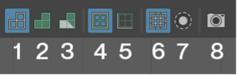
Below, you will find the menus. A few display option buttons allow you to see common UV problems more efficiently. Each of the following headings coordinates with the numbers in the image, and you will provide details about each option.
Some of the descriptions will have image sliders you must select to view how the function works.
UV Display options
Below, you will see the various UV display options and their functionality.
Wireframe view
- Toggles the wireframe on and off. (Shortcut: 4 on the keyboard).
Shaded view
- Toggles a shaded view of the UVs on and off. (Shortcut: 5 on the keyboard).
The shaded view shows which areas of the UV are facing the correct direction (blue) and which UVs are reversed (red). In addition, the shade of the colour will darken if there are multiple UVs overlapping each other (which you don't want). This shaded view will also display on the model.
The following images show the shaded areas of the hammer when this is selected.
![[ADD IMAGE'S ALT TEXT]](https://cms-uped.baseux.com/sites/default/files/Ballpeen%20Hammer%20Head%201.png)
![[ADD IMAGE'S ALT TEXT]](https://cms-uped.baseux.com/sites/default/files/Ballpeen%20Hammer%20Head%202.png)
UV Distortion
- Toggles and shaded view of the UVs on and off. (Shortcut: 7 on the keyboard)
The shaded view shows the areas of the UV which are currently being distorted. Faces that are being stretched are coloured red and faces that are being compressed are coloured blue. The colouration value indicates the amount of distortion, more red equals more stretch, and more blue equals more compression. Ideally, you want the UV faces to all be displayed white in this view. The shaded view will also be displayed on the model.
The following images show the white areas that will be displayed.
![[ADD IMAGE'S ALT TEXT]](https://cms-uped.baseux.com/sites/default/files/White%20Shading%201.png)
![[ADD IMAGE'S ALT TEXT]](https://cms-uped.baseux.com/sites/default/files/White%20Shading%202.png)
Texture Borders
- Emphasises the current boarders of the texture using colour and thickness. (Shortcut: 9 on the keyboard).
On the model, you can see where the edges of the texture are.
![[ADD IMAGE'S ALT TEXT]](https://cms-uped.baseux.com/sites/default/files/UV%20Unwrapped%201.png)
![[ADD IMAGE'S ALT TEXT]](https://cms-uped.baseux.com/sites/default/files/UV%20Unwrapped%202.png)
Shell Borders
- Toggles the colouring and thickness of selected UV shells (parts) of the model.
- (Shortcut: 8 on the keyboard).
Grid Display
- Toggles the grid in the UV Editor on and off.
Isolate Select
- View current selection in an isolate display node.
- (Shortcut: Ctrl+1 on the keyboard).
UV Snapshot
- Create a UV Snapshot for the selected object/s.
- Exports a UV image that can be painted using an image editing software.
UV Toolkit
The toolkit has several sections that can be expanded and collapsed using the arrows next to each area heading. The UV manipulation tools are in the UV Toolkit on the right of the UV Editor window.
![[ADD IMAGE'S ALT TEXT]](/sites/default/files/UV%20Toolkit%20Window.png)
Now, start learning the UV process and tools by creating a new UV arrangement for the ballpeen hammer model.
This subtopic will take you through the process of creating new UVs for the Ballpeen Hammer. If at any point you need to return to the beginning of this process, select Creating New UVs Process using your navigation bar.
Steps for creating a new UV
To create the new UV layout for the model, you will need to select a part of the model and then use Maya’s UV creation tools to project a new layout onto the model.
To do this, decide which part to select and then match a projection method from the UV toolkit, creating the new UV layout for the selected part of the model.
The various types of UV projection are located inside the Create tab of the UV Toolkit.
![[ADD IMAGE'S ALT TEXT]](/sites/default/files/Create%20Tab.png)
Begin by selecting the faces on one of the sides of the hammerhead.
![[ADD IMAGE'S ALT TEXT]](/sites/default/files/Hammerhead.png)
UV creation tools
You will be looking at the UV creation tools and decide which one matches the selected part of the geometry the closest.
There are 8 different methods of projection to choose from. The methods have been outlined in the table below.
| Projection method | Description |
|---|---|
| 1. Automatic | Maya will project UVs from several different views and generate UVs and UV shells automatically. |
| 2. Cylindrical | projects UVs from a curved plane resembling a cylinder. Best used for cylindrical shapes. |
| 3. Spherical | Like the above option, Projects UVs from a curved plane resembling a sphere. Best used for spherical shapes. |
| 4. Camera-Based | Projects UVs from a plane that is oriented with which ever camera view is currently active. |
| 5. Normal-Based | Projects UVs based on an average of the normal directions of the selected faces. |
| 6. Planar | Projects UVs from a plane of which you can select the axis of projection |
| 7. Best Plane | Projects UVs from a plane, maya will select an axis it thinks is the best. |
| 8. Contour Stretch | Projects along coordinates set by the user. Best for windy roads, undulating contours, etc. |
Based on the current selection, it is a flat plane, so you must use one of the plane-based projection methods. From the list, try to decide which plane is the best for the projection, so almost always use the Planar method.
To access the options for the tool:
- hold the Shift key and left mouse click on the Planar projection button.
An options window will appear with options for the planar mapping tool. The options you need to select in Planar Mapping Options are Project from>Insert projection before deformers.
![[ADD IMAGE'S ALT TEXT]](/sites/default/files/Planar%20Mapping%20Options.png)
You will now need to look at the faces currently selected on the model and decide which orientation is best to project the new UV layout from. You can use the colours of the move manipulator tool to assist you in this decision.
Basically, you want to project along an axis that is perpendicular to the selected faces.
![[ADD IMAGE'S ALT TEXT]](/sites/default/files/Ballpeen%20Hammerhead.png)
Looking at the move tool manipulator, the blue handle is perpendicular to the orientation of the faces and so this is the axis you want to project from.
Remember the axes in Maya are colour coded as follows:
- Red = X Axis
- Yellow = Y Axis
- Blue = Z Axis.
The manipulator handle that is perpendicular to the orientation of the faces is blue, meaning you want to project the new UV layout for this selection from the Z axis.
With the correct axis selected, you can now select apply which will make the UV protection and create the new layout for the selected faces.
A projection manipulator will appear next to the selected faces and the UVs in the UV editor will change. Hopefully the new layout will closely resemble your selected faces and appear in a blue colour.
![[ADD IMAGE'S ALT TEXT]](/sites/default/files/UV%20Shells%201.png)
You can now select the UVs in the UV editor by:
- right mouse click and hold to access the marking menu then drag the selection over to UVs.
![[ADD IMAGE'S ALT TEXT]](/sites/default/files/UV%20Marking.png)
Once you have accessed the marking menu:
- select one of the UVs that is inside the new UV shell
- if you access the UV marking menu by holding the ctrl key and the right mouse button
- you can now drag over to:
- 'To UV Shell'
- Maya will select all the UVs within the shell.
![[ADD IMAGE'S ALT TEXT]](/sites/default/files/UV%20Shell%202.png)
You can now use the move tool to move the UVs for this shell out of the way and place them in a free space where there are no other UVs.
![[ADD IMAGE'S ALT TEXT]](/sites/default/files/UV%20Shells%203.png)
Repeat this projection process for the opposite side of the hammer.
- Select the faces you want to project new UVs onto.
- Choose a projection method and orientation (for the other side of the hammerhead you can use the same planar projection method and the same projection axis, because again the side of the hammer is roughly flat and is oriented in the same direction as the previous projection.)
- Select apply once you have the selection and orientation made.
Again, a projection handle will appear and the UV layout in the UV editor will change. Although this time the UVs are shaded red.
![[ADD IMAGE'S ALT TEXT]](/sites/default/files/UV%20Shaded%20Red.png)
The red indicates, the new UV is inside out with the front face which displays the texture facing the wrong way in the UV space.
You can still select the UV shell in the UV editor and move all the UVs into some space to work on them further and fix the issue.
![[ADD IMAGE'S ALT TEXT]](/sites/default/files/Red%20%26%20Blue%20UV%20Shells.png)
To fix this problem with the UVs you need to flip the shell, so the UVs face the correct way.
To do this you can use the UV marking menu:
- press shift and hold right mouse button from the menu
- select: Flip.
![[ADD IMAGE'S ALT TEXT]](https://cms-uped.baseux.com/sites/default/files/Red%20UV%20Shell.png)
![[ADD IMAGE'S ALT TEXT]](https://cms-uped.baseux.com/sites/default/files/Blue%20UV%20Shells.png)
The UVs now face in the correct direction and the texture will be applied to the outside of the model.
Now that you have used the planar projection tool a few times, you can carry on with the other roughly flat portions of the hammer head.
The top, bottom, hammer head face and the peen can all be created using the planar projection method. Remember to check the correct orientation of the planar projection and that you have all the faces for that side selected before selecting apply.
If your new UVs don’t look quite right after the projection, then have another look at the selection and check if you have projected in the correct axis or if you have missing faces from the selection.
All red shells will need to be flipped so that they appear blue in the shaded view.
![[ADD IMAGE'S ALT TEXT]](https://cms-uped.baseux.com/sites/default/files/Top%20Of%20The%20Hammer%201.png)
![[ADD IMAGE'S ALT TEXT]](https://cms-uped.baseux.com/sites/default/files/Top%20Of%20The%20Hammer%202.png)
![[ADD IMAGE'S ALT TEXT]](https://cms-uped.baseux.com/sites/default/files/Top%20Of%20The%20Hammer%203.png)
Once you have completed the planar projection of all the roughly flat portions of the model, your model and UV editor should look something like the example in the example below.
An arrangement of UV shells that all closely resemble the shapes of the model and are shaded blue.
![[ADD IMAGE'S ALT TEXT]](/sites/default/files/UV%20Shells%20Arrangement.png)
Create remining UV shells
You now need to create the remaining UV shells for the curved sections of the hammerhead. The steps outlined below, guide you through this process.
- Select the faces of the section of the model that you want to create new UVs.
![[ADD IMAGE'S ALT TEXT]](/sites/default/files/Selected%20Faces.png)
Because the shape of these sections is cylindrical, you will need to use the cylindrical projection mapping method. You can access this function from the UV toolkit:
- select cylindrical mapping.
![[ADD IMAGE'S ALT TEXT]](/sites/default/files/LD%20Toolkit.png)
- The cylindrical mapping manipulator will appear.
![[ADD IMAGE'S ALT TEXT]](/sites/default/files/Cylindrical%20Mapping.png)
Now, the projection is not oriented with the correct axis of the selected portion of the model; you need to adjust it, so it aligns with the selected faces.
You can switch to the projection mapping manipulator handle by:
- select the small red T at the bottom of the mapping manipulator.
When you select the T button, the moving scale and rotate manipulator will appear. To access the rotation axes:
- the left mouse click on the yellow circle, revealing the three rotation axes handles.
![[ADD IMAGE'S ALT TEXT]](https://cms-uped.baseux.com/sites/default/files/Rotate%20Manipulator.png)
![[ADD IMAGE'S ALT TEXT]](https://cms-uped.baseux.com/sites/default/files/Three%20Rotation%20Axes.png)
Using the rotation handles, adjust the projection so that it aligns with the faces that are being mapped.
You can use the attribute editor to make sure that the rotation values are exactly aligning with the faces by inputting an exact value like 90 degrees or –90 degrees etc., depending on the orientation of the faces you are currently mapping.
![[ADD IMAGE'S ALT TEXT]](https://cms-uped.baseux.com/sites/default/files/Attribute%20Editor%201_0.png)
![[ADD IMAGE'S ALT TEXT]](https://cms-uped.baseux.com/sites/default/files/Attribute%20Editor%202_0.png)
Note: You may need to rotate more than one axis to align the projection with the faces of the model. In this projection, both the rotate X and Y values have been changed to allow the projection to wrap around the faces being mapped correctly.
![[ADD IMAGE'S ALT TEXT]](https://cms-uped.baseux.com/sites/default/files/Rotate%20Manipulator%202.png)
![[ADD IMAGE'S ALT TEXT]](https://cms-uped.baseux.com/sites/default/files/Attribute%20Editor%203.png)
Your next step will be to:
- check to see where the seam of the UV shell is located.
- you may need to rotate the projection around the model to get the seam to move to the underside of the model so that it can be hidden from view.
Your new shell can now be moved into its own space in the UV editor. Remember if the shell is red, then it will need to be flipped.
![[ADD IMAGE'S ALT TEXT]](/sites/default/files/Blue%20UV%20Shells%203.png)
- Continue creating the rest of the cylindrical UV maps using the same process.
Once you have completed the shells your UV editor should look similar to the example below.
![[ADD IMAGE'S ALT TEXT]](/sites/default/files/Cylindrical%20Map%20Shells.png)
Mapping the inside of the hammerhead shaft
There is still one area of the model that has not yet been UV mapped, and that is the inside of the hammerhead shaft.
To make working on this area easier, you can hide the handle of the hammer by:
- selecting it and pressing 'Ctrl + H' on the keyboard.
To show the handle:
- select the handle geometry in the outliner and use the keyboard shortcut 'Shift + H'.
![[ADD IMAGE'S ALT TEXT]](https://cms-uped.baseux.com/sites/default/files/Hammerhead%20Shaft%201.png)
![[ADD IMAGE'S ALT TEXT]](https://cms-uped.baseux.com/sites/default/files/Hammerhead%20Shaft%202.png)
Because this part of the model will never be seen on the inside of the hammerhead, you don't need to worry about the location of the seam of the UV shell. You will, however, need to flip the UVs so that they face the right way.
![[ADD IMAGE'S ALT TEXT]](/sites/default/files/Hammerhead%20Shaft%20UV%20Shells.png)
Once you have mapped all parts of the model there should not be any pieces of the model left over in the UV Editor.
You will need to continue to work through the model until all parts of the model have been mapped.
Unwrapping UVs
Once you have finished working through the UV mapping process, the next stage is unwrapping the UVs.
When you have models that have areas of curvature in the geometry there will inevitably be areas where the raw UV projection results in areas of compression and stretching of the texture.
The UV Distortion view gives you an indication of where there is distortion happening with the UVs of the model. When you activate the distortion view, you can see that most of the model is looking good with little to no distortion present (all the light grey areas of the model.)
You can activate the distortion view by either:
- selecting the UV distortion toggle button or
- using the keyboard shortcut 7.
![[ADD IMAGE'S ALT TEXT]](/sites/default/files/Screenshot%20Distortion%20Window.png)
There is one area that needs to be unwrapped more and that is the ballpeen head of the hammer.
![[ADD IMAGE'S ALT TEXT]](/sites/default/files/Ballpeen%20Hammerhead%20Unwrapped.png)
As you can clearly see, there is stretching of the UVs happening around the outer edges (red) and a small amount of compression happening in the centre (blue).
To try and fix this, you will need to unwrap the UVs so that they more closely relate to the actual size and shape of the faces that each UV is a part of.
- Select the UV shell for the Ballpeen Head of the hammer.
![[ADD IMAGE'S ALT TEXT]](/sites/default/files/Selected%20Ballpeen%20Hammer%20Head.png)
Using the marking menu:
- hold Shift + right mouse button
- click and drag to the unfold option
- when the unfold, option opens drag over to unfold.
![[ADD IMAGE'S ALT TEXT]](https://cms-uped.baseux.com/sites/default/files/Options%201.png)
![[ADD IMAGE'S ALT TEXT]](https://cms-uped.baseux.com/sites/default/files/Options%202.png)
Unfold tool
The unfold tool is designed to help you fix areas where compression and stretching has taken place. The unfold tool will try and spread out the UVs more evenly and try to match the spacing of the model faces for the selection. As you can see in the result, the outer edges have spread out more evenly but, unfortunately the centre has become smaller resulting in some distortion there.
![[ADD IMAGE'S ALT TEXT]](/sites/default/files/Unfold%20Tool.png)
The reason for this, is that the spherical shape of the shell constrains the UVs and cannot unwrap any further. To get around this problem, add an extra cut to the UV shell to allow the UVs to unwrap correctly.
You will need to add a seam to the bottom of the head that runs up the middle of the shape.
To create the cut, follow the steps below.
- select the edges that you’d like to cut
- use the cut button in the UV toolkit (under cut and sew).
- If you are using the Texture borders toggle, then the cut seam will show as a slightly thicker edge.
![[ADD IMAGE'S ALT TEXT]](https://cms-uped.baseux.com/sites/default/files/Cut%20Area%201.png)
![[ADD IMAGE'S ALT TEXT]](https://cms-uped.baseux.com/sites/default/files/Cut%20Area%202.png)
Now you can run the unwrap operation again and see if the result is any better.
![[ADD IMAGE'S ALT TEXT]](https://cms-uped.baseux.com/sites/default/files/Cut%20Area%203.png)
As you can see the result is slightly better but still not perfect. In this instance you need to cut the last edge up to the centre of the hammer head and then try unwrapping again.
![[ADD IMAGE'S ALT TEXT]](https://cms-uped.baseux.com/sites/default/files/Selected%20Area%201.png)
![[ADD IMAGE'S ALT TEXT]](https://cms-uped.baseux.com/sites/default/files/Selected%20Area%202.png)
As you can see, this is a much better result.
Cutting and sewing UVs
Now that all of the new UVs have been created for the head of the hammer, you can start to arrange them in the UV space.
The UV space is the area of the UV Editor that extends from 0 to 1 in the U and V directions.
![[ADD IMAGE'S ALT TEXT]](/sites/default/files/UV%20Space.png)
When you export your UV snapshot after completing the UV process, any UV shells inside this area will be included.
To arrange your shells, you must organise them in the UV space about each other. The process for this has been outlined in the steps below.
- Organise UV Shells
- Arrange the UV shells in the UV space relative to each other. Shells adjacent to each other on the model should be correctly located and oriented in the UV space.
- Locate and Move Shells:
- Start by locating one of the sides of the hammerhead.
- Move this piece into the UV space.
- Select and Align Edges:
- Select one of the top edges of the shell.
- With one of the shell's border edges selected, identify the corresponding edge it connects to. The corresponding edge on that shell will also appear selected.
![[ADD IMAGE'S ALT TEXT]](/sites/default/files/Blue%20Shells.png)
Now you know which parts connect to each other you can select and move this shell into the UV space and arrange it next to the piece it connects to.
![[ADD IMAGE'S ALT TEXT]](/sites/default/files/Selected%20UV%20Shells.png)
As you can see, these pieces connect, but now the top shell is oriented with the connecting edge facing away from its connecting piece on the first shell. This means that you need to rotate the UVs so that the two edges match up, and then you can move and sew the two shells together along their connecting edges.
To rotate the UVs:
- Select the shell you want to rotate and in the UV toolkit under the Transform section.
- In the tools area you can find rotate.
![[ADD IMAGE'S ALT TEXT]](/sites/default/files/Tools%20Window.png)
The rotate tool is currently set up to rotate 90 degrees with each click of the two direction buttons to the right of the degrees field. You can set the degrees amount yourself if desired, but 90 degrees is the default value.
To connect the two edges, you must spin your shell around 180 degrees to click on the rotate button two times.
The two edges are next to each other in the UV space.
![[ADD IMAGE'S ALT TEXT]](/sites/default/files/UV%20Space%202.png)
Now, you can select the edge or edges that you would like to reconnect and, use the Move and Sew tool to move the two pieces together and sew the selected edges back together to create one UV shell where there were two before.
The steps below outline the reconnecting process.
Reconnect Edges Using Move and Sew Tool.
- Select the edge or edges you would like to reconnect.
- Use the Move and Sew tool to move the two pieces together and sew the selected edges back together to create one UV shell from the two.
- To use the Move and Sew tool:
- First, select the edge/edges that are to be sewn together.
- Then, use the marking menu (Shift and right mouse click) and drag up to the Move and Sew Edges tool.
![[ADD IMAGE'S ALT TEXT]](/sites/default/files/Sew%20Tool.png)
- The two pieces will be moved closer to each other and then sewn along the selected edge.
![[ADD IMAGE'S ALT TEXT]](/sites/default/files/Two%20Pieces.png)
By now, you will have gone through the process of identifying the pieces of the model’s UV that connect. You can go through the rest of the parts of the hammerhead and arrange them according to their connecting edges, then use the Move and Sew tool to connect them back together.
![[ADD IMAGE'S ALT TEXT]](https://cms-uped.baseux.com/sites/default/files/Connected%20Edges%201.png)
![[ADD IMAGE'S ALT TEXT]](https://cms-uped.baseux.com/sites/default/files/Connected%20Edges%202.png)
Important
Suppose you find that you have shells that are different scales from each other when you try to match up the connecting edges. Use the scale tool to scale the UVs so that the two connecting edges are the same length. This will ensure that the UV shells stay as you mapped them when sewing the pieces back together.
Note that these two shells do not match the scale. The selected shell is larger than the shell you have already sewn together.
Use the Scale tool to adjust the size of the UV shell to match the scale along the connecting edge. Then, you can move and sew the two pieces together.
![[ADD IMAGE'S ALT TEXT]](https://cms-uped.baseux.com/sites/default/files/Selected%20Shell%201.png)
![[ADD IMAGE'S ALT TEXT]](https://cms-uped.baseux.com/sites/default/files/Selected%20Shell%202.png)
![[ADD IMAGE'S ALT TEXT]](https://cms-uped.baseux.com/sites/default/files/Selected%20Shell%203.png)
With these connecting parts of the hammer head completed you can arrange the shells in the UV space.
Select each shell, scale them down and begin arranging them within the UV space.
While arranging, try to think about the scale of each shell, trying to keep them all around the same scale about each other.
Another consideration to remember when arranging the shells is how much detail each piece will need. If you have shells requiring higher detail levels, such as a character's face, then you will want to scale that shell up and give it more space inside the UV area.
Keep shells next to each other on the model in the UV space, too.
Tip
Make sure that none of the shells overlap with each other in the UV space. If they overlap, then the overlapping area of texture will be visible on both overlapping parts of the model.
![[ADD IMAGE'S ALT TEXT]](/sites/default/files/Shells%20Kept%20Close.png)
Now that you have completed the UV for the hammer head, you need to complete the UV process for the handle of the hammer.
UV the hammer handle
To start the process of adding UV to the hammer handle, you will need to use planar mapping for the top and bottom of the handle.
![[ADD IMAGE'S ALT TEXT]](https://cms-uped.baseux.com/sites/default/files/Planar%20Options.png)
![[ADD IMAGE'S ALT TEXT]](https://cms-uped.baseux.com/sites/default/files/Planar%20Options%202.png)
Remember to flip the UVs for any shells that are reversed.
The shaft of the handle is a cylindrical shape so, use the cylindrical mapping method to generate new UVs for the handle. Because there is a step on the shape of the shaft you may choose to UV the top section of the handle separately from the bottom.
![[ADD IMAGE'S ALT TEXT]](https://cms-uped.baseux.com/sites/default/files/Cylindrical%20Mapping%201.png)
![[ADD IMAGE'S ALT TEXT]](https://cms-uped.baseux.com/sites/default/files/Cylindrical%20Mapping%202.png)
The shaft of the handle will need to be unwrapped to remove as much of the UV distortion as possible.
![[ADD IMAGE'S ALT TEXT]](https://cms-uped.baseux.com/sites/default/files/Unwrapped%20Handle%201.png)
![[ADD IMAGE'S ALT TEXT]](https://cms-uped.baseux.com/sites/default/files/Unwrapped%20Handle%202.png)
With the handle mapped and unwrapped you can add it to your UV shell arrangement with the hammer head.
Ensure you have both pieces of geometry selected and then move and scale the handle UV shell so that it fits into the space left in the UV area.
![[ADD IMAGE'S ALT TEXT]](/sites/default/files/Hammer%20Handle.png)
UV a Ballpeen Hammer model
Watch the following series of video tutorials to help you through UV Mapping.
Practice
Task 4: UV the provided Ballpeen Hammer model.
Practice the UV mapping process for the Ballpeen Hammer in Maya to bring texture and realism to your 3D creations.
What tools or resources do you need?
- Autodesk Maya.
- BallpeenHammer.mb
What steps should you take?
4 Hours
- Open Maya and open the Ballpeen Hammer model.
- Follow the detailed steps in the Video tutorials to create the UVs for each part of the 3D model.
- Use the Unfold tool to unfold the parts so that textures are not distorted on the surface of the model.
- Apply a checker pattern to identify distortions and fine-tune individual UVs using Move and Scale tools.
- Inspect and resolve any overlapping UVs and arrange UV shells logically within the 0 to 1 UV space.
- Review UV layout for consistency and correctness and save your work.
- Export the final UV map using the UV Snapshot Tool.
What should you do after?
- Reflect on the importance of UV mapping in 3D modeling and answer the following questions.
- How does this skill contribute to the overall quality of your projects?
- Share any innovative or unique approaches you used to organise and arrange UV shells efficiently within the 0 to 1 UV space.
- How might the skills you've gained in UV mapping be applicable to other 3D modeling projects?
- Share your Ballpeen Hammer to forum
- Select your forum thread in Forum: Texturing.
- Select Reply to your first Forum post.
- Enter the words ‘Task 4- Ballpeen Hammer UV’ in your reply.
- Select the Post your response button, then select Edit in your new reply when it shows up.
- Upload your photo(s) or files using the Attachment field.
- Select Save changes to share your coursework to your forum thread.
- Get feedback on this and other learning tasks at the next Live Session – check the Live Session calendar for dates and times. All live sessions are recorded so you can watch them later if you miss a session.
Practice your UV mapping skills further in the next task; Create a UV layout for your Spacecraft Model.
UV a spacecraft model
You can begin to cement your understanding of the UV process by using the same UV workflow and tools to create a new UV layout for another model.
Use what you have learned about the UV process and tools from the Ballpeen hammer UV activity to create a new UV layout for your own spacecraft model.
You can watch the full UV process used for the Spacecraft model in the demonstration video below. In the video you will observe the UV process which will help to refresh your memory of the steps and thinking behind breaking up a model and the challenges of unwrapping and arranging the various UV shells.
The example below, shows what you will be working with initially.
![[ADD IMAGE'S ALT TEXT]](/sites/default/files/Split%20View.png)
And this is the UV layout when complete.
![[ADD IMAGE'S ALT TEXT]](/sites/default/files/UV%20Layout.png)
Before completing the next learning task, watch the following video tutorial series to guide you through a UV layout for your spacecraft model.
Practice
Task 5: Create a UV layout for your spacecraft model.
Use what you have learned about the UV process and tools from the Ballpeen Hammer UV activity to create a new UV layout for your own spacecraft model.
What tools or resources do you need?
- Your spacecraft model.
- Autodesk Maya.
What steps should you take?
6 Hours
Set aside up to six hours to complete steps 2-10 below. Remember to save your work as you go when using Maya.
- Review the video series Create a UV layout for your spacecraft model and the learning content for creating new UVs to help you complete this task.
- You can also view the UV Spacecraft video to help you to UV your own spacecraft model.
- Open your spacecraft in Maya, save as a new version and open the UV editor.
- Decide which parts of the model you are going to cut up and project the first UVs. (Before making changes, create a UV snapshot for reference. (Save the snapshot for later comparison).
- Use planar mapping for flat areas of your spacecraft.
- Identify cylindrical components (like engines) and Apply 'Cylindrical Mapping' for these areas.
- Use the unfold tool in the UV editor to unwrap and help prevent distortion of the UVS.
- Check for Overlapping UVs. Inspect the UV Editor for any overlapping UVs and Resolve overlaps using 'Unfold' or 'Layout' tools.
- Arrange UV shells logically within the 0 to 1 UV space, use 'Move' and 'Rotate' tools for precise placement.
- Apply a checker pattern to identify and correct distortions and fine-tune individual UVs with the 'Move' and 'Scale' tools.
- Review the UV layout, save your work, and export the final UV map using the UV Snapshot tool.
What should you do after?
- Reflect on how you performed this task and answer the following questions.
- How did the experience of applying the UV mapping process to the spacecraft model differ from the Ballpeen Hammer, and what adjustments or considerations did you need to make?
- In what ways did your understanding of UV mapping evolve, and how might you apply these skills to different types of 3D models in the future?
- Reflect on the challenges encountered during the spacecraft UV mapping task. How did the skills developed in the Ballpeen Hammer activity contribute to overcoming these challenges?
- Share your UV Spacecraft to Forum:
- Select your forum thread in Forum: Texture.
- Select Reply to your first Forum post.
- Enter the words ‘Task 5 UV Spacecraft’ in your reply.
- Select the Post your response button, then select Edit in your new reply when it shows up.
- Upload your photo(s) or files using the Attachment field.
- Select Save changes to share your coursework to your forum thread.
- Get feedback on this and other learning tasks at the next Live Session – check the Live Session calendar for dates and times. All live sessions are recorded so you can watch them later if you miss a session.
Well done, you have completed the UV Layout for your Spacecraft. Next up, you will be creating a texture swatch for your spacecraft.
Well done on completing the Modelling topic. This topic set the foundations for your texturing work. As you wrap this topic up, think about what you;ve accomplished.
You have learnt:
- hard surface modelling
- basic modelling and the basic modelling process
- symmetrical modelling and the symmetrical modelling process
- the UV mapping process and the process of creating new UVs.
| Learning task # | Learning Task Name | Duration (Hours) | |
|---|---|---|---|
| 1 | Model a dining chair | 4 |
|
| 2 | Design and model a symmetrical spacecraft | 8 |
|
| 3 | Design and build additional 3D models | 5 |
|
| 4 | UV the provided ballpeen hammer model | 4 |
|
| 5 | Create a UV layout for your spacecraft model | 6 |
|
When you're ready, move onto the next topic, Texturing.