In this course you'll learn about fault finding in live circuits – a crucial skill for any electrician. You will learn to diagnose electrical faults, recognizing their signs, and understanding what causes them. Plus, you'll get a clear picture of the importance of solid cable connections and terminations. You'll find out about the right tools to measure continuity, resistance, insulation resistance, voltage, current, and RCD performance.
Working in damp environments requires special considerations. We'll study the requirements for damp zones outlined in AS/NZS 3000. You'll get familiar with the ins and outs of electrical protection and IP ratings, making informed decisions about fitting and equipment suitability in damp conditions, ensuring you understand how to create safe spaces where water and electricity coexist.
The course wraps up by guiding you through decommissioning and commissioning processes, along with safe appliance connections. You'll know exactly what testing is necessary before circuits are energised or appliances are put to use.
So, get ready to roll up your sleeves and dive into the practical aspects of being an electrician.
| Credits | 22 |
|---|---|
| Learning Hours | 220 |
| Learning Outcome | LO 4.1 Test basic electrical installations for safe and compliant operation. LO 4.2 Apply requirements for electrical installations in the electrical industry. LO 4.3 Decommission and commission simple electrical fittings and appliances with connection to the electrical supply LO 4.4 Diagnose electrical faults, repairs and disposal procedures for simple electrical equipment and fittings |
| Assessment | 04A 04B 04C |
You are free to plan your studies in the way that works best for you, but we know that guidance on how to do this is also helpful. We suggest following way to navigate through the learning content over the next few weeks:
| Week 1 |
Topic 1 – Testing Electrical Installations |
|---|---|
| Week 2 |
Topic 2 – Installations in Special Situations |
| Week 3 |
Topic 2 – Installations in Special Situations |
| Week 4 |
Topic 3 – Decommissioning and Recommissioning |
| Week 5 |
Topic – 4 Faults, Repairs and Disposal Procedures |
| Week 6 |
Topic – 4 Faults, Repairs and Disposal Procedures |
What we’re covering:
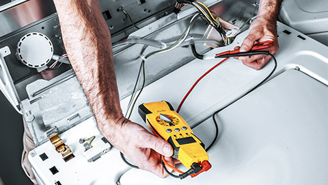
- Understand the importance of inspection, testing, and certification for electrical installations.
- Identify the key regulatory standards and compliance requirements in New Zealand.
- Explain the process and requirements for certifying electrical installations.
Introduction to Inspection, Testing, and Certification
Importance of Inspection and Testing: Inspection and testing are critical processes in ensuring that electrical installations are safe and functional. These steps help identify any potential hazards, such as faulty wiring or incorrect connections, which can lead to serious issues like electrical shocks, fires, and damage to equipment. By thoroughly inspecting and testing installations, electricians can prevent these hazards and ensure that everything operates as intended.
Certification: Certification is the process of officially documenting that an electrical installation meets all required safety and compliance standards. This certification is not only a legal requirement but also provides peace of mind to property owners and occupants that the electrical systems are safe to use. Certifications are necessary for all new installations, as well as any significant alterations or repairs to existing systems.
Key Regulatory Standards in New Zealand
Let’s take a moment to review some of the key legislation in New Zealand that impacts on the process of testing and certification. You will remember this information from learning content in earlier modules of this programme.
Electricity Act 1992: The Electricity Act 1992 is the primary legislation governing electrical safety in New Zealand. It outlines the responsibilities of electricians and inspectors, setting out the legal framework to ensure electrical installations are safe. Compliance with this Act is crucial to avoid legal penalties and to protect public safety.
Electricity (Safety) Regulations 2010: These regulations provide specific requirements for electrical installations. They detail the standards that must be met and the procedures that must be followed to ensure safety. The regulations cover everything from the installation of wiring systems to the maintenance of electrical equipment, highlighting the importance of adherence to these standards in everyday electrical work.
Standards and Codes of Practice - The AS/NZS 3000: Electrical Installations standard, also known as the Australian/New Zealand Wiring Rules, is a key document that electricians must follow. It sets out the fundamental principles and requirements for safe electrical installations. Understanding and applying these standards is essential for ensuring compliance and safety in all electrical work.
Inspection Requirements
Initial Inspection: Initial inspections are conducted to ensure that electrical installations are carried out correctly and safely from the start. This involves checking that all materials used are appropriate and that the installation adheres to the design specifications. Visual checks include examining the condition of cables, connections, and protective devices to ensure they are correctly installed and in good condition.
Periodic Inspection: Periodic inspections are necessary to maintain the safety and compliance of electrical installations over time. These inspections help identify wear and tear, environmental damage, and potential faults that could develop into serious issues if left unaddressed. Regular inspections are a proactive measure to ensure ongoing safety.
Inspection Checklist: An inspection checklist is a detailed document that guides electricians through the process of inspecting an electrical installation. It ensures that no aspect of the installation is overlooked and provides a structured approach to documenting and reporting findings. Using a checklist helps maintain consistency and thoroughness in inspections.
The WorkSafe website has example checklists that can be downloaded and used: Electrical certification and record of inspection templates | WorkSafe
Testing Requirements
Types of Tests: Various tests are conducted to ensure the safety and compliance of electrical installations. These include:
- Insulation resistance testing: Measures the resistance of insulation materials to prevent electrical leakage.
- Earth continuity testing: Checks the continuity of the earth conductor to ensure it is properly connected and functioning.
- Polarity testing: Verifies that the live, neutral, and earth wires are correctly connected.
- Functionality testing of residual current devices (RCDs): Ensures RCDs operate correctly to protect against electrical shocks.
The following videos go through each of the tests listed above.
Watch
Insulation Resistance
This video produced by Master Electricians New Zealand goes through the steps of performing an insulation resistance test.
Expected Duration: 6:16 minutes
Questions
Pre Watch Question: Before you start watching, what tools do you think will be used during this test. Make a note of them to check your ideas as you watch.
Earth Continuity Test
This video produced by Master Electricians New Zealand goes through the steps of performing an earth continuity test.
Expected Duration: 5:42 minutes
Questions
Pre Watch Question: Before you start watching, what things to you think will be covered in the test? What steps do you guess the electrician will need to follow? Make a note of them to check your ideas as you watch.
Testing Circuit Polarity
This video produced by Master Electricians New Zealand goes through the steps of performing polarity testing.
Expected Duration: 4:30 minutes
Questions
Pre Watch Question: Before you start watching, what safety measures do you expect to see the electrician taking while they perform the test? Make a note of them to check your ideas as you watch.
RCD
This video produced by Master Electricians New Zealand goes through the steps of RCD testing.
Expected Duration: 3:27 minutes
Questions
Pre Watch Question: What readings do you expect to see on each of the tools that the electrician uses if everything has been installed correctly and there are no faults? Make a note of them to check your ideas as you watch.
Using Testing Equipment: To perform these tests, electricians use specific tools such as multimeters, insulation testers, and earth loop impedance testers. It's important to handle these tools safely and correctly to obtain accurate results and avoid personal injury.
Recording Test Results: Accurate documentation of test results is crucial. It provides a record that the installation has been tested and found to be safe and compliant. Properly recording results also helps in identifying any necessary remedial actions and ensures traceability for future reference.
Certification Process
Certification Documentation: There are two main types of certification documentation:
- Certificates of Compliance (CoC): These confirm that an installation complies with the necessary standards and regulations.
- Electrical Safety Certificates (ESC): These provide assurance that the installation is safe for use.
Both documents must include specific information such as the details of the installation, the tests conducted, and the results obtained.
Process for Certification: The certification process involves several steps, starting from the initial installation and ending with the final certification. This includes conducting inspections and tests, completing the necessary documentation, and obtaining the required signatures from qualified personnel. The role of the inspector and the electrician is crucial in ensuring that all steps are followed correctly.
Importance of Accurate Record-Keeping: Maintaining accurate records is a legal requirement. It ensures accountability and provides a detailed history of the installation, which is important for future inspections and maintenance. Accurate record-keeping also helps in resolving any disputes or issues that may arise.
This video takes you through the process of completing CoC and ESC in New Zealand.
Watch
Understanding New Zealand COC & ESC Forms
Learn more about how to easily certify your electrical work with Tradify's digital CoC and ESC form templates in New Zealand
Expected Duration: 1:00 minutes
Questions
Pre Watch Question: Before you watch, download the template CoC and ESC from the WorkSafe site linked at the start of this topic. Compare these with the examples used in the Tradify videos.
Post Watch Task: Read over the advice that Tradify offers around why these forms are needed, who needs to use them, and when they need to be used. How To Fill Out a Certificate of Compliance | Tradify™ (tradifyhq.com)
Explore
To apply the concepts learned, let's walk through an example scenario. In this activity you will take the role of an apprentice electrician needing to ensure that the installation job you are working on is safe and compliant. Follow this link for the scenario.
What we’re covering:
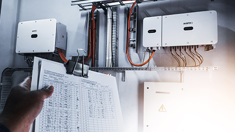
- Understand the various methods for examining electrical installations.
- Identify potential hazards in electrical installations.
- Apply safety protocols and best practices during examinations.
Methods for Examining Electrical Installations
Visual Inspection
A visual inspection is the first step in examining electrical installations. This involves looking for obvious signs of damage or issues, such as:
- Damaged or exposed wiring: Check for frayed insulation, cuts, or abrasions on wires.
- Loose connections: Ensure all connections are tight and secure.
- Signs of overheating: Look for discoloration, burn marks, or melting on wires, connectors, and outlets.
Testing
Testing is essential to verify the integrity and safety of an electrical installation. Basic tools used include multimeters, insulation testers, and continuity testers. Key tests include:
Insulation resistance testing: Measures the resistance of insulation materials to ensure there is no electrical leakage.
Continuity testing: Checks if electrical paths are continuous and unbroken.
Polarity testing: Ensures that live, neutral, and earth wires are correctly connected.
Review these tests in the previous topic if you are unsure of what is involved.
Functional Testing
Functional testing ensures that all electrical components and systems operate as intended. This includes:
- Checking the operation of lighting, switches, and outlets.
- Verifying the functionality of safety devices like circuit breakers and RCDs.
- Testing appliances and equipment connected to the installation.
Documentation
Keeping detailed records is crucial for tracking the condition of electrical installations. Use standardized forms and checklists to document findings systematically. This ensures consistency and helps in identifying patterns or recurring issues.
Identifying Potential Hazards
Common Electrical Hazards
Understanding common electrical hazards is key to preventing accidents:
- Overloaded Circuits: An overloaded circuit can cause overheating and fires. Signs include frequently tripping breakers and warm or discolored outlets.
- Faulty Wiring: Look for signs of wear, damage, or incorrect installation. This includes frayed wires, exposed conductors, and improper connections.
- Poor Connections: Loose or corroded connections can lead to arcing and overheating, posing serious risks.
Environmental Factors
Environmental conditions can significantly impact electrical safety:
Moisture and Water Exposure: Water can cause short circuits and electrical shocks. Look for signs of water damage or exposure, especially in areas prone to moisture.
Temperature Extremes: Both high and low temperatures can affect electrical components. Check for signs of heat damage or brittle, cracked insulation in cold environments.
Physical Damage Risks: Identify areas where electrical installations are vulnerable to physical damage, such as high-traffic zones or areas with heavy equipment.
Human Error
Human error is a common cause of electrical hazards:
Installation Mistakes: Incorrect wiring, poor connections, and not following installation guidelines can lead to safety issues.
Maintenance Errors: Inadequate or improper maintenance can result in dangerous conditions. Always follow proper procedures and guidelines.
Safety Protocols and Best Practices
Personal Protective Equipment (PPE)
Using the right PPE is essential for safety:
- Gloves: Insulated gloves protect against electrical shocks.
- Safety Glasses: Protect your eyes from sparks and debris.
- Insulated Tools: Use tools with insulated handles to reduce the risk of electrical shock.
Safe Work Practices
Adopting safe work practices helps prevent accidents:
- Power Off: Always ensure the power is off before starting any inspection or work.
- Lockout/Tagout Procedures: Use lockout/tagout procedures to prevent accidental energizing of circuits while working on them.
- Clean Work Area: Keep the work area clean and organized to prevent accidents and ensure easy access to tools and equipment.
Emergency Procedures
Knowing how to respond to emergencies is crucial:
- Electrical Shocks and Injuries: Be prepared to provide first aid and call emergency services if someone receives an electrical shock.
- Fire Safety: Identify electrical fire hazards and know how to use appropriate fire extinguishers for electrical fires.
Best Practices
Adhering to best practices enhances safety and efficiency:
- Double-Checking Work: Always double-check your work to ensure no steps are missed.
- Staying Updated: Keep up-to-date with current regulations, standards, and best practices.
- Continuous Learning: Engage in continuous learning and training to improve your skills and knowledge.
The following case studies show what the processes from this topic look like in a work-based context.
Case Study
Visual Inspection and Testing
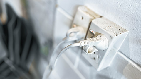
A local community center has reported flickering lights and frequent tripping of circuit breakers. As an electrical trainee, you are asked to perform an inspection (with your supervisor) and identify any issues.
You know that the first thing you need to do is perform a visual inspection which includes:
- Inspecting the visible wiring for any signs of damage, such as frayed insulation, cuts, or abrasions.
- Checking all connections for tightness and security.
- Looking for signs of overheating, such as discoloration, burn marks, or melting on wires, connectors, and outlets.
During your visual inspection, you notice the following:
- A section of wiring in the main hall has frayed insulation and exposed conductors.
- There are burn marks on one of the outlets near the kitchen area, indicating possible overheating.
- Several connections in the electrical panel are loose and show signs of corrosion.
You perform the required tests. During the Insulation Resistance Testing you use a multimeter to measure the insulation resistance of the wiring in the main hall. You get a reading of 0.5 MΩ, indicating a potential issue as the resistance should be much higher for a safe installation.
Then you perform Continuity Tests on the circuits, particularly in the section with the frayed wiring. The test shows a break in continuity, confirming that the electrical path is not continuous.
Finally you conduct polarity tests on the outlet near the kitchen. The test reveals that the live and neutral wires are reversed, which can be dangerous and contribute to the overheating issue.
Now that you and your supervisor know what the issues are, you perform the necessary repairs. You:
- Replace the section of wiring in the main hall with frayed insulation and exposed conductors.
- Replace the outlet near the kitchen and ensure proper connections.
- Tighten and clean the loose and corroded connections in the electrical panel.
Once the repairs are done you complete functional testing to make sure the issues have been resolved. You:
- Check the operation of all lighting, switches, and outlets: All devices now operate correctly without flickering or failure.
- Test the circuit breakers and RCDs and determine that they function correctly, without tripping unnecessarily.
- Test all appliances and equipment connected to the installation. Everything works as expected without any signs of malfunction.
The issues reported by the community center, including flickering lights and frequent tripping of circuit breakers, were resolved after the repairs. The functional testing confirmed that the electrical installation is now operating safely and efficiently. Your supervisor completes the necessary documentation to confirm that the work has been completed to a safe and compliant standard.
Case Study
Identifying Potential Hazards
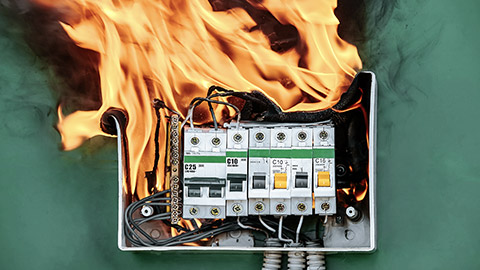
A small retail store has experienced a small electrical fire caused by an overloaded circuit. You and your supervisor have been tasked with conducting a thorough inspection to identify any other potential hazards.
Your supervisor asks you to perform the following tasks:
- Inspect the electrical panel and circuits for signs of overloading, such as frequently tripping breakers and warm or discolored outlets.
- Check for faulty wiring, including frayed wires, exposed conductors, and improper connections.
- Examine connections for signs of looseness or corrosion that could lead to arcing and overheating.
During your inspection, you notice the following:
- Several breakers in the electrical panel are warm to the touch and show signs of discoloration, indicating potential overloading.
- There are multiple instances of frayed wires and exposed conductors in the storage area.
- A few connections in the electrical panel are loose and corroded, which could lead to arcing and overheating.
- In one section of the store, you find that an overloaded power strip is being used to power multiple high-wattage appliances, contributing to the circuit overload.
You and your supervisor then inspect the shop for any environmental factors that could cause a further hazard. You are looking for things like:
- moisture and water exposure, especially in locations prone to spills or leaks.
- the impact of temperature extremes on electrical components, like heat damage or brittle, cracked insulation.
- electrical installations that could be vulnerable to physical damage, such as high-traffic zones or areas with heavy equipment.
During your assessment, you find:
- Signs of water damage near the back of the store where cleaning supplies are stored, with some outlets showing signs of moisture exposure.
- Heat damage on wiring insulation in areas near heating units, causing the insulation to become brittle and cracked.
- Electrical installations in high-traffic zones have protective covers missing, making them vulnerable to physical damage.
- The environmental factor contributing to the overloaded power strip hazard is the store's poorly ventilated storage area, causing excessive heat buildup.
You and your supervisor then:
- Review installations in the shop for any mistakes, such as incorrect wiring, poor connections, and failure to follow installation guidelines.
- Examine the maintenance records to ensure proper procedures and guidelines have been followed when installing or making repairs
As a result of your inspection you and your supervisor find and report back to the owner of the shop on the following potential hazards:
- Incorrect wiring in several outlets, with live and neutral wires reversed.
- Several connections made with improper techniques, not following standard installation guidelines.
- Maintenance records show inconsistent checks and some missed maintenance routines.
The shop owner advises your supervisor that during a previous renovation, a less experienced electrician (a family friend) installed the electrical panel. You and your supervisor have a discussion about how failing to adhere to load balancing guidelines most likely contributed to the circuit overload and eventual fire in the shop.
As part of your training your supervisor asks you:
“What steps would you recommend to mitigate the identified hazards?”
Write your ideas in the forum - 4.1.2 CASE STUDY - Identifying Potential Hazards.

What we’re covering:
- Understand the procedures for testing electrical installations.
- Learn to use tools and equipment for electrical testing.
- Interpret test results to ensure safety and compliance.
Procedures for Testing Electrical Installations
Now that you are more than halfway through this qualification, many of the things in the learning content will be familiar to you. Safety procedures should be one of these things. However, let’s review them here again.
Pre-Test Preparations
Before starting any tests, it's essential to ensure the safety of yourself and others. Follow these steps:
- Power Isolation: Always isolate the power supply before testing. Use proper lockout/tagout procedures to prevent accidental re-energization.
- Visual Inspection: Conduct a preliminary visual inspection to identify any obvious issues, such as damaged wires or loose connections. Address these issues before proceeding with further tests.
Types of Tests and Their Importance
There are several key tests to perform when testing electrical installations. We introduced them in an earlier topic in this module. They are:
Insulation Resistance Testing
This test checks the quality of the insulation around conductors to prevent electrical leakage. A high resistance value indicates good insulation, while a low value suggests potential issues.
Earth Continuity Testing
This test verifies that the earth connection is intact and provides a safe path for fault currents. It ensures the safety of the installation by preventing electric shocks.
Polarity Testing
This test ensures that the live, neutral, and earth wires are correctly connected. Proper polarity is crucial for the safe operation of electrical equipment.
Residual Current Device (RCD) Testing
This test verifies that RCDs operate correctly and disconnect the circuit when a fault is detected. RCDs are essential for preventing electric shocks and fires.
Step-by-Step Testing Procedures
Let’s review the detailed steps for each type of test.
Tools and Equipment for Electrical Testing
Common Testing Tools
Several tools are commonly used in electrical testing. You should be well familiar with what each tool does and how to use it by this point in the learning. However, here’s review for you:
- Multimeters
Used to measure voltage, current, and resistance. Ensure the multimeter is set to the correct measurement type and range before use. - Insulation Testers
Used to measure the resistance of insulation materials. Connect the tester according to the manufacturer’s instructions and interpret the readings. - Earth Loop Impedance Testers
Used to measure the impedance of the earth fault loop. Follow the testing procedure to ensure accurate results. - RCD Testers
Used to test the functionality of residual current devices. Simulate fault conditions and measure the response time.
Proper Handling and Safety Precautions
- Always follow the manufacturer’s guidelines for using testing tools.
- Ensure tools are properly calibrated and maintained.
- Use insulated tools and wear appropriate PPE (Personal Protective Equipment) such as gloves and safety glasses.
- Double-check connections and settings before conducting any tests to prevent damage to equipment or personal injury.
Interpreting Test Results
Understanding Test Readings
Interpreting test results is crucial for determining the safety and compliance of an electrical installation:
Normal vs. Abnormal Readings
Understand what constitutes normal readings for each type of test. For example, a high insulation resistance value is normal, while a low value indicates potential issues.
Identify common issues such as low insulation resistance, high earth loop impedance, or incorrect polarity, and understand their implications for the safety of the installation.
Here are some scenarios and readings for each test based on New Zealand standards and practices:
Insulation Resistance Testing: You are inspecting the wiring of a newly installed lighting circuit in a residential building in Auckland. Which of the following readings indicates a normal/expected response for the situation? Decide, then click the + button to see if you were correct or not.
The insulation resistance between conductors and earth is measured to be 500 MΩ, indicating good insulation integrity.
The insulation resistance measurement shows 5 MΩ, which is significantly lower than expected. This suggests a potential insulation breakdown or moisture ingress, requiring further investigation and possible remediation.
Earth Continuity Testing: You are conducting earth continuity testing on the main distribution board of a commercial building in Wellington. Which of the following readings indicates a normal/expected response for the situation? Decide, then click the + button to see if you were correct or not.
The continuity test fails to show any reading, indicating an open circuit. This suggests a poor or broken earth connection, which needs immediate attention to ensure safety and compliance.
The continuity test between the earth point and the exposed conductive part shows a reading of 0.1 Ω, indicating a low resistance path and a good earth connection.
Polarity Testing: You are verifying the electrical connections in a newly renovated kitchen in Christchurch. Which of the following readings indicates a normal/expected response for the situation? Decide, then click the + button to see if you were correct or not.
The polarity tester shows that the live and neutral wires are reversed. This misconnection can lead to potential hazards such as electric shock and equipment malfunction, requiring immediate correction.
The polarity tester indicates that the live, neutral, and earth wires are correctly connected as per the wiring diagram, ensuring safe operation of electrical appliances.
RCD Testing: You are testing the residual current devices (RCDs) in a newly constructed office building in Hamilton. Which of the following readings indicates a normal/expected response for the situation? Decide, then click the + button to see if you were correct or not.
The RCD trips within the specified time and current rating (e.g., 30 mA), indicating it is functioning correctly to protect against electrical faults.
The RCD either does not trip or trips slowly during testing, indicating a potential fault in the device or its installation. This requires immediate investigation and repair to ensure proper protection against electrical hazards.
Documentation and Reporting
Accurate documentation of test results is essential for compliance and future reference:
Recording Results
Use standardized forms and templates to record test results, such as the ones provided on the WorkSafe website. Ensure all fields are completed accurately.
Include details such as the date of the test, the equipment used, the measured values, and any observations or notes.
Reporting Findings
Compile the test results into a clear and organized report.
Highlight any issues or non-compliance found during testing.
Provide recommendations for corrective actions if necessary.
Here are two examples of what a report might look like:
Insulation Resistance Testing
Date: 26 June, 2024
Location: Residential Building, Auckland
Inspection Details:
- Procedure: Insulation Resistance Testing
- Tool Used: Insulation Tester
Findings:
During the insulation resistance testing of the newly installed lighting circuit, the following observations were made:
- Insulation Resistance Reading:*500 MΩ
- The insulation resistance between conductors and earth was measured at 500 MΩ, which is well within acceptable limits. This indicates good insulation integrity throughout the circuit.
Issues or Non-Compliance:
No issues or non-compliance were identified during this testing phase. All readings were within expected parameters, indicating a well-installed and insulated electrical system.
Recommendations:
Based on the findings of the insulation resistance testing, no corrective actions are required at this time. Regular maintenance checks should be conducted to ensure continued integrity of the insulation.
Conclusion:
The electrical installation in the residential building has passed the insulation resistance testing without any issues. The system is deemed safe and compliant with current regulations.
Insulation Resistance Testing
Date: 26 June, 2024
Location: Residential Building, Auckland
Inspection Details:
- Procedure: Insulation Resistance Testing
- Tool Used: Insulation Tester
Findings:
During the insulation resistance testing of the newly installed lighting circuit, the following observations were made:
- Insulation Resistance Reading: 5 MΩ
- The insulation resistance between conductors and earth was measured at 5 MΩ, which is significantly lower than expected. This indicates a potential issue with insulation integrity, possibly due to moisture ingress or insulation degradation.
Issues or Non-Compliance:
The low insulation resistance reading suggests a potential insulation breakdown or moisture ingress, which poses a safety hazard.
Recommendations:
Immediate corrective actions are recommended to address the low insulation resistance:
- Conduct further investigation to identify the source of moisture or insulation damage.
- Repair or replace the affected wiring or insulation to restore proper insulation integrity.
- Perform re-testing after repairs to ensure compliance with safety standards.
Conclusion:
The current insulation resistance testing has revealed a significant issue that requires prompt attention to ensure the safety and compliance of the electrical installation in the residential building.
Explore
Use the example reports above from the insulation resistance testing scenario to write one report about the abnormal result from the scenarios above for either:
- Polarity testing
- Earth continuity testing
- RCD Testing
What we’re covering:
- Understand the different types of electrical fittings and components.
- Learn the uses and applications of various electrical fittings and components.
- Identify and understand electrical accessories and their applications.
Overview of Electrical Fittings and Components
Definition and Importance
Electrical fittings and components are essential parts of any electrical installation. They include devices and accessories that are used to connect, protect, and manage electrical circuits. These components ensure the safe and effective operation of electrical systems by providing secure connections and protection against electrical faults.
Common Electrical Fittings and Components
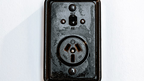
Outlets and Receptacles: Devices that provide a connection point for electrical appliances and equipment.
Switches: Devices used to control the flow of electricity to lights and other electrical devices.
Junction Boxes and Enclosures: Protective housings for electrical connections, preventing accidental contact and providing a mounting point for wiring.
Conduits and Conduit Fittings: Tubes used to protect and route electrical wiring, available in various materials such as PVC, EMT (electrical metallic tubing), and flexible conduits.
Connectors and Terminals: Devices used to join electrical conductors securely and reliably.
Uses and Applications of Electrical Fittings and Components
Outlets and Receptacles
Types:
- Standard Outlets: Used for general electrical connections in homes and buildings.
- GFCI (Ground Fault Circuit Interrupter) Outlets: Designed to protect against electrical shock by shutting off power when a ground fault is detected.
- AFCI (Arc Fault Circuit Interrupter) Outlets: Protect against electrical fires by detecting and interrupting arc faults.
Watch
Socket Outlets - Aussie Wiring Rules & Rough-in/Fit off
This video shows how to wire a CFCI socket. It’s from Australia, but as you should be aware of by now New Zealand and Australia share the same standards for wiring, so the information applies to NZ installations as well.
Expected Duration: 13:13 minutes
Applications:
- Residential: Commonly used in living areas, kitchens, and bathrooms.
- Commercial: Found in offices, retail spaces, and public buildings.
- Industrial: Used in factories, warehouses, and other industrial environments.
Switches
Types:
- Single-Pole Switches: Control a single light or device from one location.
- Three-Way Switches: Allow control of a light or device from two different locations.
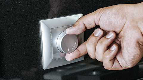
- Dimmer Switches: Adjust the brightness of lights.
Applications and Installation Considerations:
- Ensure proper wiring and connections.
- Follow manufacturer's instructions and local electrical codes.
Junction Boxes and Enclosures
Purpose and Types:
- Metal Junction Boxes: Provide a durable and fire-resistant housing for electrical connections.
- Plastic Junction Boxes: Lightweight and non-conductive, suitable for various applications.
- Proper Installation Methods and Safety Considerations:
- Securely mount junction boxes to structures.
- Ensure all connections are enclosed and protected.
Conduits and Conduit Fittings
Types:
- PVC Conduits: Non-metallic and resistant to corrosion, suitable for outdoor and underground applications.
- EMT (Electrical Metallic Tubing): Lightweight and easy to bend, used for indoor wiring.
- Flexible Conduits: Provide flexibility in routing wiring around obstacles.
Uses:
- Protect electrical wiring from physical damage and environmental factors.
- Route wiring through walls, ceilings, and floors.
Connectors and Terminals
Types:
- Wire Nuts: Twist-on connectors used to join multiple wires.
- Terminal Blocks: Modular blocks used to secure and organize multiple wire connections.
- Crimp Connectors: Used to join wires securely by crimping a metal sleeve around them.
Importance of Secure and Reliable Connections:
- Prevent electrical faults and ensure safe operation.
- Follow proper techniques for making secure connections.
Identifying Electrical Accessories and Their Applications
Common Electrical Accessories
Plugs and Sockets: Connect appliances to the power supply. Ensure proper voltage and current ratings.
Extension Cords and Power Strips: Provide additional outlets and flexibility in connecting devices. Use rated for the load and avoid overloading.
Lighting Fixtures and Controls
Types of Lighting Fixtures:
- Ceiling Lights: Provide general illumination for rooms.
- Wall Sconces: Add accent lighting and decorative elements.
- LED Panels: Offer energy-efficient lighting solutions.
- Lighting Controls:
- Dimmers: Adjust the brightness of lights to save energy and create ambiance.
- Timers: Automatically turn lights on and off at set times.
- Motion Sensors: Activate lights when movement is detected, enhancing security and convenience.
Safety Devices
- Circuit Breakers: Automatically interrupt the electrical flow in case of an overload or short circuit.
- Fuses: Protect against overcurrent by melting and breaking the circuit.
- Residual Current Devices (RCDs): Protect against electrical shocks by disconnecting the circuit when a fault is detected.
Specialty Components
- Surge Protectors: Protect electronic devices from voltage spikes.
- Uninterruptible Power Supplies (UPS): Provide backup power during outages, protecting sensitive equipment.
- Smart Home Devices: Include smart switches, plugs, and lighting systems that can be controlled remotely via smartphone apps.
Explore
Check your learning so far by completing this activity on electrical fittings.
Read the following scenarios and use what you have learned to provide a solution for each one. You can type your answers then save them to a pdf that you can download to your own device and keep as a record of your learning. If you are unsure of your answers, then you can show your pdf to your tutor and ask them for feedback the next time that you are on campus.

What we’re covering:
- Understand the procedures for installing and connecting electrical fittings, components, and appliances.
- Learn to test installations for safety and proper operation.
- Apply knowledge of electrical fittings and components in practical installations.
Installation Procedures
Planning and Preparation
Proper planning and preparation are crucial for successful electrical installations. This involves:
Assessing the Installation Site:
- Evaluate the layout and determine the best locations for outlets, switches, and other components.
- Identify potential challenges such as limited space or accessibility issues.
Selecting Appropriate Fittings, Components, and Appliances:
- Choose the right type and rating of components based on the installation requirements.
- Ensure compatibility with the existing electrical system and the specific needs of the site.
Step-by-Step Installation
Follow these steps for installing various electrical fittings and components:
Installing Outlets, Switches, and Junction Boxes:
- Mark the locations and cut openings for installation.
- Securely mount the outlets, switches, and junction boxes to the structure.
- Run the necessary wiring and make secure connections.
Routing and Securing Conduits and Wiring:
- Use conduits to protect and organize wiring.
- Secure conduits to the structure and ensure proper routing to avoid damage or interference.
Connecting Appliances and Ensuring Proper Integration:
- Follow manufacturer guidelines for connecting appliances.
- Ensure all connections are secure and that appliances are properly integrated into the electrical system.
Ensuring Compliance
Adhering to electrical codes and standards is essential for safety and compliance:
Following Electrical Codes and Standards:
- Stay updated with local and national electrical codes.
- Ensure all installations meet the required standards for safety and performance.
Adhering to Manufacturer Guidelines and Best Practices:
- Follow the instructions provided by manufacturers for installing and connecting their products.
- Apply industry best practices to ensure safe and reliable installations.
Testing for Safety and Proper Operation
Initial Checks
Before conducting detailed tests, perform initial checks:
Visual Inspection of the Installation:
- Look for any obvious issues such as damaged components or incorrect wiring.
- Ensure all components are securely mounted and protected.
Verifying Connections and Ensuring No Loose Wires:
- Check all connections to ensure they are tight and secure.
- Address any loose or exposed wires to prevent potential hazards.
Electrical Tests
Perform the following tests to verify the safety and proper operation of the installation:
Continuity Testing:
- Use a continuity tester to ensure all electrical paths are complete and unbroken.
- Verify that all switches, outlets, and other components are properly connected.
Insulation Resistance Testing:
- Measure the resistance of insulation materials to ensure there is no electrical leakage.
- High resistance values indicate good insulation, while low values suggest potential issues.
Functional Testing:
- Operate all components and appliances to ensure they work correctly.
- Check the functionality of switches, outlets, and any connected appliances.
Safety Verification
Ensuring the safety of the installation is a critical step:
Checking the Operation of Safety Devices:
- Test residual current devices (RCDs) and circuit breakers to ensure they function correctly.
- Verify that these safety devices can disconnect the circuit in case of a fault.
Ensuring Proper Grounding and Bonding:
- Check that all exposed metal parts are properly grounded.
- Ensure that bonding is in place to prevent electrical shock hazards.
Practical Application
Read the case studies below and then answer the following questions.
Case Study
Residential Installation
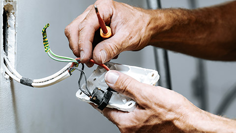
Hone is an electrician in Auckland, New Zealand, tasked with installing outlets and lighting in a newly built home in a suburban area. The home has a modern design with an open-plan living space, three bedrooms, two bathrooms, and a kitchen. The homeowners, a young couple, want the electrical installation to be discreet, functional, and aesthetically pleasing. They are also concerned about safety, particularly in the bathrooms and kitchen.
Hone faces several challenges: the limited space in certain areas like the bathrooms, ensuring the installation is accessible and safe for all users, and maintaining the sleek design of the home. He needs to use compact fittings, carefully plan the installation to meet the aesthetic standards, and ensure compliance with local safety regulations.
Case Study
Commercial Installation

A tech startup in Wellington, New Zealand, is moving into a new office space. The office needs to be wired to accommodate multiple workstations, a conference room, a kitchen area, and a server room. The startup operates on a tight schedule and cannot afford significant downtime during the installation process. Additionally, the office will have a high electrical load due to the numerous computers, servers, and other electronic devices.
Sarah, the electrician assigned to this project, must handle the challenges of a high electrical load, the need for multiple circuits, and ensuring minimal disruption to the startup’s operations. She needs to calculate the electrical load accurately, use commercial-grade components, and plan a phased installation schedule to minimize downtime.
