What we're covering:
- Electrical Faults – open circuit, short circuit, ground fault, overloads, sags and surges.
- Control methods - preventative, diagnostics & correction.
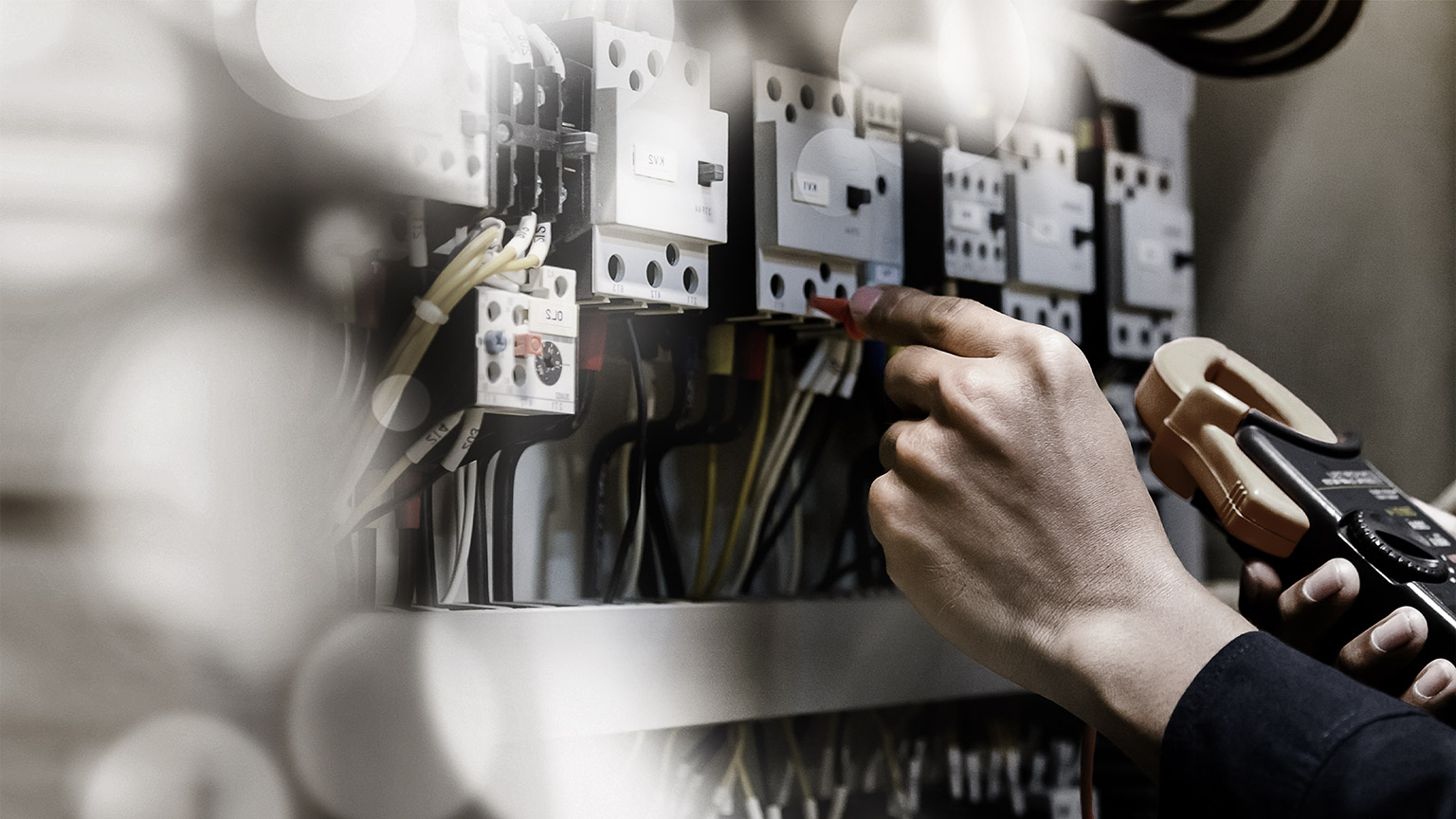
What is an electric fault?
An electrical fault is an abnormal condition in a power system or equipment. It happens when the current flowing through a circuit is partially or completely interrupted.
Faults can occur for various reasons, including equipment failure, environmental conditions, and human error. Some common causes of faults include faulty wiring, damaged insulation, overloaded circuits, lightning strikes, power surges, and voltage fluctuations.
The signs of a fault can vary depending on the type of fault and the location of the fault. However, some common indications of an electrical fault include flickering lights, circuit breakers tripping frequently, burning smells, and overheating equipment.
Detecting and understanding the symptoms and causes of electrical faults is essential for maintaining the reliability of systems, reducing downtime, and ensuring the safety of both equipment and individuals.
You can prevent faults from occurring by following proper safety practices, which includes regular maintenance and inspection of equipment, using the correct type and size of electrical components, and avoiding overloading circuits. It is also essential to safeguard power systems by using protective devices like circuit breakers and relays.
Types of electrical faults
The most common types of faults include open circuit faults, short circuit faults, and ground faults.
Open Circuits
An open circuit fault happens when the path that electricity follows is broken or interrupted. This can occur due to damaged wires, blown fuses, or disconnected parts of the circuit. When this situation arises, the flow of electricity is halted, causing devices or systems connected to that circuit to stop working. This interruption can result in the failure of devices or systems dependent on that circuit.
| Symptoms | Causes |
|---|---|
|
|
Short Circuits
A short circuit fault occurs when two conductors with different electrical potentials directly touch, creating a pathway with very low resistance for the current to flow through. (Usually when a "Live" wire touches a "Neutral" wire or an "Earth" wire.) This situation leads to an overflow of current, which can have severe consequences such as fires or damage to equipment. In simpler terms, it's like two wires that shouldn't touch suddenly coming into contact and causing a rush of electricity.
| Symptoms | Causes |
|---|---|
|
|
Ground Faults
A ground fault happens when an unintended connection between a live conductor and ground occurs, often due to insulation breakdown. This can lead to safety hazards, such as electric shocks.
| Symptoms | Causes |
|---|---|
|
|
Overloads
Overloads occur when a circuit is subjected to a higher current than it can handle, often due to excessive load or faulty devices. This can lead to overheating, component damage, power outages and fire hazards.
| Symptoms | Causes |
|---|---|
|
|
Voltage Sags and Surges
Voltage sags (dips) and surges (spikes) are temporary deviations from the standard voltage level. Sags can lead to equipment malfunctions, while surges can cause immediate damage.
| Symptoms | Causes |
|---|---|
|
|
Harmonics
Harmonics are non-standard frequencies that can distort the sinusoidal waveform of alternating current. These can result from nonlinear loads and cause overheating in devices.
| Symptoms | Causes |
|---|---|
|
|
Control methods

Electrical issues are common, but we can reduce their impact by preventing, detecting, and fixing them promptly in order to avoid greater damage to equipment and personnel:
Preventive Measures
- Regular inspections and maintenance to identify and rectify potential faults before they cause disruptions.
- Proper training for personnel to ensure correct wiring and installation practices.
- Using high-quality materials and components to minimise the risk of faults.
Diagnostic Techniques
- Infrared thermography to identify hotspots caused by excessive resistance.
- Megohmmeter testing to assess insulation resistance.
- Current and voltage analysis to detect imbalances.
Fault Correction
- Isolation and repair of faulty components or connections.
- Replacement of damaged cables or insulation.
- Ensuring proper grounding and bonding.
Strategies for specific faults
Overloads and Short Circuits
- Install appropriate circuit protection devices (fuses, circuit breakers and protective relays).
- Design systems with safety margins to handle transient overloads.
- Balance loads across phases.
Voltage Sags and Surges
- Implement voltage regulation devices.
- Install surge protection devices (SPDs) and lightning protectors.
- Consider uninterruptible power supply (UPS) systems for critical equipment.
Harmonics
- Use harmonic filters to mitigate distortion.
- Avoid excessive use of nonlinear loads.
- Balance phase loads and improve power factor.
Activity
Email your solutions to the following issues to your tutor.
- You're in a workshop, and the lights suddenly flicker when a large machine starts. Explain why this happens and suggest a simple way to prevent it.
- Your computer shuts down unexpectedly during a thunderstorm. Why might this happen, and what basic measure could you take to safeguard your computer?
- A hair dryer suddenly stops working. Describe a step-by-step approach to determine whether it's an open circuit or a short circuit fault causing the issue.
- Explain how using too many devices on the same power strip can lead to a safety hazard and suggest an alternative arrangement.
- A kitchen appliance experiences a ground fault. What danger does this pose, and how can you protect yourself from such a hazard?

What we're covering:
- Cable terminations and connections – what to look for.
- Causes of cable termination faults.
Secure and well-made cable terminations and connections are vital for safe and dependable electrical current transmission, reducing risks like overheating, arcing, and voltage drops. Faulty connections can result in various problems, such as equipment damage, outages, safety risks, and potential fires.
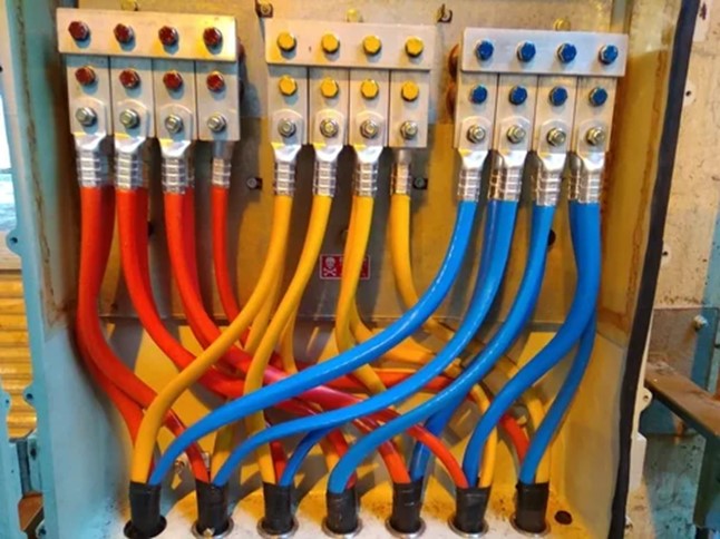
Here's what to look for in secure and well-made cable terminations and connections:
Proper Tools and Materials
Ensure that appropriate tools, connectors, and materials are used for the specific type of cables being connected. This includes selecting the correct size and type of connectors, insulating materials, and any necessary protective devices.
Clean Stripping
Cable insulation should be stripped cleanly and evenly, without damaging the underlying conductor. Avoid over-stripping, which could expose too much of the conductor and increase the risk of short circuits.
Correct Connector Type
Choose connectors that are designed for the specific cable type and application. Connectors should match the size and material of the cable and provide a secure and snug fit.
Proper Crimping or Tightening
Use appropriate crimping tools or methods to secure connectors to the cables. Crimps should be tight and uniform, providing consistent pressure to ensure a strong and lasting connection. For screw-type connections, ensure proper torque is applied according to manufacturer specifications.
Insulation Integrity
Insulation materials (such as heat shrink tubing or electrical tape) should be applied to cover the exposed conductor and connector, preventing contact with other conductive surfaces and reducing the risk of short circuits.
Strain Relief
Implement strain relief mechanisms to prevent excessive tension on the cable, especially at the point of termination. Strain relief can involve using cable glands, clamps, or other devices to secure the cable and reduce mechanical stress on the connection.
Proper Orientation
Ensure that cables are properly oriented and aligned within the connectors. This prevents crossed or twisted connections that could lead to poor conductivity and increased resistance.
Visual Inspection
Perform a thorough visual inspection of the termination to check for any signs of damage, poor alignment, or inadequate insulation. Look for irregularities such as exposed conductors, uneven crimps, or loose connectors.
Pull Test
After making a connection, perform a gentle pull test to ensure that the cable is securely attached to the connector. It should not come loose or detach under reasonable stress.
Documentation
Keep detailed records of the termination process, including connector types, sizes, torque values, and any other relevant information. Proper documentation helps with troubleshooting, maintenance, and future modifications.
Compliance
Ensure all terminations and connections adhere to relevant electrical codes, standards, and regulations. Non-compliance can lead to safety hazards and legal issues.
Testing
Depending on the application, consider conducting appropriate electrical tests, such as continuity tests or insulation resistance tests, to verify the integrity of the connections and ensure proper functionality.
Activity
Complete the table in this worksheet summarising the importance of secure well-made cable terminations and connections.
Activity
Four common causes of cable termination faults are:
- Poor Workmanship.
- Corrosion.
- Mechanical Stress.
- Environmental Factors
Write a brief explanation (2-3 sentences) for each cause, detailing how it contributes to the occurrence of cable termination faults. There is space on the worksheet for Exercise 14 for you to do this.
Activity
Test your learning via this set of multi-choice questions.

What we're covering:
- Fault diagnosis – gather and analyze information, find fault, resolve issue and check system before reconnection.
Identifying and resolving issues, conducting repairs, and reinstating the functionality of an electrical system are essential components of electrical installation. While the goal is always to achieve error-free installations, the reality is that unforeseen problems can arise. Mistakes and defects may surface during installation, and encountering faulty components, fittings, fixtures, or cables is a normal part of the job.
This is the reason that as an electrician you must test and commission any installation, and the reason that you must learn fault-finding (diagnostic) techniques. The ability to diagnose and resolve issues within an electrical system is a vital skill set. In addition, you must have a solid grasp of how to effectively use testing instruments to tackle these situations.
Ensure you take a step-by-step approach when fault finding:
Step 1
Start fault finding by gathering all the important details about what happened. Talk to as many people as you can who were there when the problem occurred. They might have seen or know something that can help. There are three main things you should do:
- Find out what doesn’t work - figure out which parts of the equipment or system are not working like they should. This helps you understand where the problem is.
- Ask questions - talk to people who saw the problem happen. Ask them about what they noticed and when it happened. They might have noticed things you didn't.
- Observe the equipment or system closely - use all your senses to gather information. Listen for any unusual sounds, feel for anything hot or cold, and see if anything looks strange.
Remember, you should focus on collecting information that matters and might help solve the problem. If you're not sure if something is important, include it for now. You can decide later if it's needed.
Refer to any manufacturer’s documentation and data. Sometimes this has useful information.
Check the diagnostics list or self-diagnostics facility where available if it's available.
And don't forget, the person who uses the equipment regularly can give you important details. They know how things should work and can tell you about what they've seen before.
Here are some important things to write down:
- Did the equipment suddenly stop working or did it gradually slow down over time?
- Did anything happen to the equipment, like getting wet or being dropped?
- Did you smell something burning or see smoke?
- Was there any bright light or sparks?
- Is there any visible damage?
- Can you turn the equipment's parts by hand?
- Do switches make the usual sounds when you use them?
- Do the small brushes move freely in the brush boxes?
By gathering this key information, you're building a strong foundation to help you figure out what's wrong and how to fix it.
Step 2
Next comes the crucial step of analysing information, where you use the details you've gathered to figure out what's likely causing the problem. This step involves:
- Consider everything you know - look at all the information you've collected. If something doesn't seem important after thinking more about it, you can leave it out. Focus on the most important details.
- Find the key clues - concentrate on the most relevant pieces of information. Use logical thinking to connect the dots and come up with a possible reason for the problem. You might not know exactly what's wrong, but you can figure out the general area where the issue might be.
- Use past experience and training - think about problems you've seen before or things you've learned in your training. Sometimes, similar issues have happened in the past, and you can use that knowledge to help you understand what's going on now.
- Check previous faults - if there's a record of similar problems happening before, it can give you hints about what might be wrong this time.
- Look at how often it happens - if this kind of problem has occurred frequently in the past, it could suggest a specific cause.
- Consult the manufacturer’s information - the documents that came with the equipment might have useful information about common problems and how to fix them. Also, if the equipment has self-diagnostic features, check the results.
By analysing all of this information, you can make an educated guess about what's likely causing the problem and focus your efforts on the right direction.
Step 3
This is where you use your prior analysis to find the fault. By methodically applying investigation techniques and conducting appropriate tests, you should uncover the root of the problem. Investigative techniques to find the fault include:
- Observation - looking for any visible signs of damage, wear, or irregularities in the equipment or system.
- Simulation - you may be able to recreate the conditions that led to the fault. This might involve using diagnostic data provided by the manufacturer or utilizing built-in diagnostic tools if available.

If there are no visible defects, you should proceed to electrical testing:
- Continuity Test - check there is a continuous path for the electrical current through the components, such as the motor, heating element, or solenoid.
- Insulation Test - verify there are no low-resistance faults between conductors and earth. For low-voltage systems, the reading should be higher than 1 megaohm.
- Energise - If it's safe to do so, turn on the equipment and observe its behaviour. See if it's operating as expected, making an educated guess about what might be causing the problem based on these observations.
- Further tests - Conduct additional tests to confirm your initial assumption.
There are three main approaches you can take to track down faults in electrical systems. Choose the one that fits the equipment and circumstances you're dealing with.

Direct Path Approach
- Start by isolating the power supply to ensure safety.
- Check that all control switches are in the closed position.
- Use an ohmmeter to connect across the circuit terminals. This should reveal a load resistance, such as around 23-24 ohms for a 2.4 kW heating element.
- If the load resistance isn't present, check the connection of the neutral or return conductor.
- Move step by step along the circuit, testing until you find where the resistance returns.
- Only turn the power supply back on when insulation and continuity tests confirm it's safe to do so.
Reverse Path Approach (Working Backwards)
This approach is suited for control circuits where activating a contactor coil is necessary. It involves tracing the path backwards from the end to identify the fault.
- Begin by turning off the power supply to ensure safety,
- Use an ohmmeter set to around 1000 ohms to check the coil's existence (approximately 600 ohms for a 230V coil),
- Test the continuity of the return wire back or neutral to the power supply.
- Connect one end of the ohmmeter to the return wire, then trace back along the supply side, checking switches and contacts until the connection is lost,
Middle-Out Approach
This method is effective for more intricate systems, particularly those controlled by a programmable logic controller (PLC) or programmable relay. It works on the concept of starting from the middle and working your way out through the circuit.
- Begin by taking measurements and examining the circuit from the middle.
- Move in one direction through the circuit, observing and measuring as you go.
- If the fault isn't evident, move in the opposite direction from the middle, investigating and measuring components along the way.
- A PLC, which can monitor input devices and display their operation through illuminated LEDs, is an ideal starting point.
- Check the output LEDs for energised output devices, and also perform a physical inspection to verify the operation of devices like contactors or solenoids.
A word of warning…
Assumptions from Observed Effects
Keep in mind that the assumptions you make about the fault's cause should be carefully evaluated. False assumptions can lead you down the wrong path and waste time. Always verify the soundness of each assumption through thorough follow-up.
For instance, you should not assume a switch is making contact just because it is in the ‘ON’ position. Similarly, don’t assume two parts are identical just because the replacement part has the same part number as the original.
Activity
Step 4
Once the fault has been identified, it's time to take action and resolve the issue.
This step involves both:
- Determining and removing the root cause of the fault to ensure a lasting solution. Just fixing the immediate problem won't ensure it doesn't happen again. Think about a flickering light in a room. Just changing the bulb won't help if the real problem, like a loose wire connection, is still there.
- Safely repairing the fault. Once you know where the problem started, start fixing it step by step. This can involve doing a variety of things, like making small changes or doing more complex repairs. The process of fixing is like putting together all the insights gained from earlier steps in the fault-finding process.
Preventing recurring faults is a proactive approach to repairs. Strengthen weak points, use upgraded components, and ensure proper lubrication and cleaning. Adjust maintenance intervals based on wear and tear patterns and provide training for proper equipment use. Keep detailed records to track trends and make targeted improvements. This strategy enhances equipment durability, reduces downtime, and saves resources in the long run.
Intermittent faults can be a challenge, especially in areas with high vibration. Regular checks of terminals are crucial, as vibrations can cause nuts and screws to loosen over time. To combat this issue, consider using vibration-absorbing mounts and ensuring proper protection with washers on both sides of clamped surfaces.
Metal fatigue, particularly in aluminum conductors and busbars, is another concern. Monitor these components closely to detect signs of wear and deterioration. Implementing vibration-absorbing mounting techniques can help mitigate metal fatigue and extend the lifespan of these elements.
Step 5
- After rectifying the fault, the final step involves carefully checking the system for proper functioning and safety before it is put back into use. This involves a diligent testing process to ensure that everything is back to normal and operating smoothly.
- Electrical safety tests ensure that the electrical components and connections are safe and meet the required standards, while operational tests check the equipment's actual functioning.
Activity
Work on these questions and complete during your SDL time. Email your answers to your tutor.
- What are the essential steps involved in identifying and resolving faults in an electrical installation?
- Name some sources of information that can aid in fault finding during Step 1- the gathering information stage.
- Imagine you are called to investigate a malfunctioning lighting circuit. Describe the type of information you would gather during Step 1 to assist in fault finding.
- What is the purpose of the analysis step (Step 2) in fault finding?
- During Step 2 of fault finding, how might past experience and training be useful in analysing information?
- List some techniques mentioned for analysing information during Step 2.
- In Step 3, what are some investigative techniques used to find the fault in an electrical system?
- Suppose you have a motor that is not starting. Describe which investigative techniques you would use to identify the fault in the motor.
- What is the primary purpose of the Direct Path Approach in fault finding, and when might it be preferred?
- In which type of scenario would the Reverse Path Approach be most suitable for fault finding?
- Suppose you have a circuit breaker that keeps tripping due to overloading. Describe how you would resolve this issue after identifying the root cause.
- Develop a checklist of safety tests that need to be conducted after resolving a fault in an electrical system.
- Why is it important to conduct operational tests as part of Step 5 after resolving a fault?
- You are called to investigate a situation where a motor is intermittently stopping during operation. Describe the steps you would take to systematically identify and resolve the issue.
- A lighting circuit is not functioning in a specific area. Describe how you would apply investigative techniques to find the fault and outline the sequence of tests you would perform.

What we're covering:
- Using test instruments – measuring continuity, resistance, insulation resistance, RCD performance.
Electrical measurements are crucial for ensuring the safety, reliability, and optimal performance of electrical systems. Accurate testing and assessment are essential to identify potential faults, troubleshoot issues, and ensure compliance with industry standards.
By now you should be familiar with a variety of test instruments and how to use each effectively. The following section is intended to be revision rather than new material.
Measuring conductor continuity
Conductor continuity testing is a process to ensure the integrity of electrical pathways and the absence of breaks or interruptions. Conductor continuity testers, digital multimeters, and analog multimeters are suitable instruments for quickly identifying breaks in circuits, ensuring reliable current flow and maintaining the integrity of electrical connections.
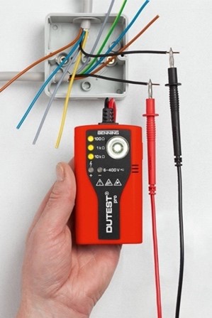
Conductor Continuity Tester
A conductor continuity tester, often referred to as a buzzer or beeper, is a simple and cost-effective tool used to determine whether a circuit is complete or broken. It emits an audible sound or a visual indicator when a continuous path for current flow exists.
Operation:
- Ensure the circuit is de-energised before conducting any tests.
- Connect the test leads of the continuity tester to the points of the circuit being tested (e.g., two ends of a wire or connection).
- The conductor continuity tester will emit an audible sound or display a visual signal if the circuit is complete (continuous).
- If the circuit is broken or interrupted, there will be no sound or visual indication.
Digital Multimeter (DMM)
A digital multimeter is a versatile instrument that can measure various electrical parameters, including continuity. Many modern DMMs include a dedicated continuity test mode.
Operation:
- Set the DMM to the continuity or diode test mode, often indicated by a symbol resembling a sound wave (∿) or diode icon.
- Ensure the circuit is de-energised before testing.
- Touch the test leads together briefly to verify that the continuity function is functioning correctly.
- Connect the test leads to the two points of the circuit being tested.
- The DMM will emit a beep or display a specific symbol (such as "0.000" or "1") if the circuit is continuous.
- If the circuit is interrupted, the DMM will display an open circuit symbol or not emit a beep.
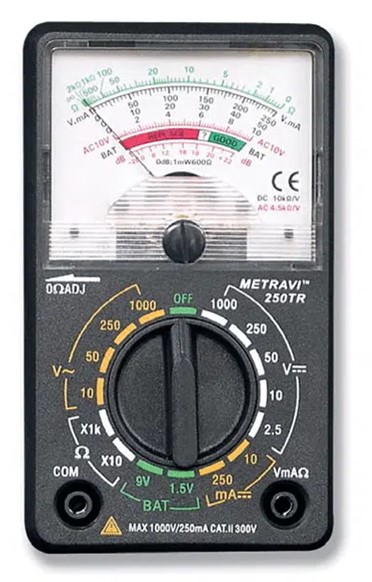
Analog Multimeter
Analog multimeters, although less common than digital ones, can also be used for continuity testing. They provide a visual indication of continuity using a needle on a scale.
Operation:
- Set the analog multimeter to the lowest resistance range or the continuity setting if available.
- Ensure the circuit is de-energised.
- Connect the test leads to the circuit points to be tested.
- The analog needle will deflect to the right or indicate a value close to zero if the circuit is continuous.
- If the circuit is open, the needle will not move, indicating no continuity.
Clamp Meter
A clamp meter is used to measure the current flowing through a conductor without breaking the circuit. Clamp meters typically measure AC current only. They are useful in monitoring current draw of devices to ensure they're operating within expected ranges; diagnosing issues like overloaded circuits, imbalanced loads, or faulty components; and verifying the functionality of circuit breakers, fuses, and safety switches.
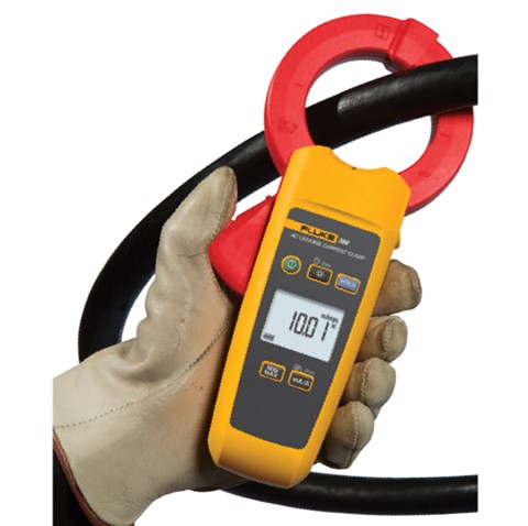
Operation:
- The clamp meter's jaw is opened and placed around the conductor.
- When current flows through the conductor, it generates a magnetic field around the wire.
- The ‘Hall Effect’ sensor in the clamp detects the strength of the magnetic field.
- The sensor converts the magnetic field strength into an electrical signal.
- The signal is then processed by the meter's electronics to display the current reading on the meter's display.
Measuring resistance
Measuring resistance is essential for assessing the flow of current diagnosing faults, optimizing circuit performance, and ensuring the proper functioning of components.
Digital multimeters and ohmmeters can efficiently evaluate resistive elements within electrical systems.
Digital Multimeter (DMM)
A digital multimeter (DMM) is a versatile and widely used tool that can measure various electrical parameters, including resistance. It provides precise and quick resistance readings.
Operation:
- Ensure the circuit is de-energised before performing resistance measurements.
- Set the DMM to the resistance (Ω) measurement mode.
- Connect the test leads to the component or points being tested.
- For accurate readings, avoid touching the test leads or the measured object while taking measurements.
- Read the displayed resistance value on the DMM screen.
- For components with low resistance values, switch to a lower resistance range on the DMM to get a more accurate reading.
Ohmmeter
An ohmmeter is a dedicated instrument designed specifically for measuring resistance. It is available in both analog and digital versions.

Operation:
- Ensure the circuit is de-energised before conducting resistance measurements.
- Set the ohmmeter to the appropriate resistance range based on the expected resistance value.
- Connect the test leads to the component or points being tested.
- Observe the resistance value displayed on the ohmmeter's scale or screen.
- If using an analog ohmmeter, read the needle position on the scale for the resistance value.
- For accurate measurements, ensure the test leads are securely connected and avoid touching the measured object while taking readings.
Activity
Discuss the appropriate test instruments for measuring Voltage and describe how to use each instrument effectively. Email your tutor with your answers.
Activity
Discuss the appropriate test instruments for measuring Current and describe how to use each instrument effectively. Email your tutor with your answers.
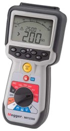
Measuring insulation resistance
Measuring insulation resistance is used to assess the quality of insulation materials and detect potential faults that could compromise the safety and performance of electrical systems. Insulation resistance testers (Meggers), insulation resistance measurement functions in digital multimeters, and analog insulation testers are suitable instruments for this purpose.
Insulation Resistance Tester (Megger)
An insulation resistance tester, commonly referred to as a Megger, is a specialised instrument designed specifically for measuring insulation resistance. It applies a high voltage across the insulation material and measures the resulting current to assess the insulation's integrity.
Operation:
- De-energize the circuit and ensure all components are disconnected from the system under test.
- Select the appropriate test voltage on the Megger, considering the insulation system's rating.
- Connect one test lead to the conductor under test and the other lead to the grounded component or structure.
- Initiate the insulation resistance test, and the Megger will apply the test voltage and measure the resulting current.
- Observe the insulation resistance value displayed on the Megger's screen or scale.
- Compare the measured insulation resistance value to acceptable industry standards or manufacturer specifications.
Digital Multimeter (DMM)
Some digital multimeters offer an insulation resistance measurement function, typically using a lower test voltage compared to dedicated insulation resistance testers.
Operation:
- De-energize the circuit and ensure all components are disconnected from the system under test.
- Set the DMM to the insulation resistance measurement mode.
- Connect one test lead to the conductor under test and the other lead to the grounded component or structure.
- Initiate the measurement, and the DMM will apply a test voltage and measure the resulting current.
- Observe the insulation resistance value displayed on the DMM's screen.
- Ensure that the measured value meets applicable insulation resistance requirements and guidelines.
Analog Insulation Testers
Analog insulation testers, although less common than digital versions, are still used for measuring insulation resistance. They provide a visual indication of insulation quality based on the deflection of a needle on a scale.
Operation:
- De-energize the circuit and ensure all components are disconnected from the system under test.
- Set the analog insulation tester to the appropriate test voltage and resistance range.
- Connect one test lead to the conductor under test and the other lead to the grounded component or structure.
- Observe the needle deflection on the scale. A higher deflection indicates better insulation quality.
- Compare the deflection to acceptable levels specified by industry standards or guidelines.
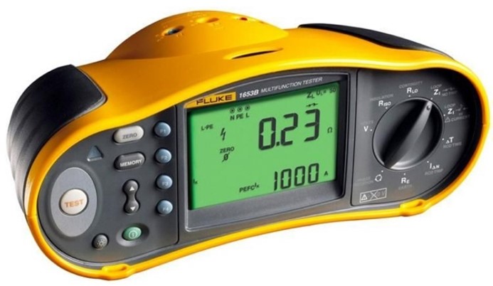
Measuring RCD performance
Measuring RCD performance is vital to ensure electrical protection's safety and effectiveness. Instruments like RCD testers, multifunction installation testers, and RCD trip time testers assess RCD functionality. Proper usage and result interpretation within safety standards and specifications allow electricians to confirm RCDs' proper operation, enhancing system safety and reducing electric shock and fault risks.
Residual Current Device Tester
An RCD tester, or loop tester, is a specialised tool designed specifically for testing the performance of RCDs. It simulates fault conditions to assess the RCD's response time and sensitivity.

Operation:
- Ensure the circuit is de-energised and the RCD is in the OFF position before performing tests.
- Connect the RCD tester to the RCD's test points, following the manufacturer's instructions.
- Select the appropriate test mode on the RCD tester (e.g., trip time, trip current, or ramp test).
- Initiate the test, and the RCD tester will simulate a fault condition to assess the RCD's response.
- Observe the test results displayed on the RCD tester's screen, which may include trip time, trip current, or other relevant parameters.
- Compare the measured values to the RCD's specifications and relevant safety standards to ensure proper performance.
Multifunction Installation Tester
A multifunction installation tester is a versatile instrument used for various electrical tests, including RCD performance testing.
Operation:
- De-energize the circuit and ensure the RCD is in the OFF position before conducting tests.
- Connect the multifunction tester to the RCD's test points, following the manufacturer's guidelines.
- Select the appropriate RCD test mode on the instrument.
- Initiate the test, and the multifunction tester will apply the required test signals to assess the RCD's performance.
- Review the displayed test results, which may include trip time, trip current, and other relevant data.
- Compare the measured values with industry standards and RCD specifications to verify proper functioning.
RCD Trip Time Tester (Stopwatch Method)
The RCD trip time tester uses a simple stopwatch method to measure the time it takes for an RCD to trip in response to a simulated fault condition.
Operation:
- De-energize the circuit and ensure the RCD is in the OFF position before conducting tests.
- Prepare a known fault condition (e.g., a resistor connected in parallel to the RCD's protected circuit).
- Manually reset the RCD to the ON position.
- Activate the fault condition and simultaneously start the stopwatch.
- Observe the stopwatch and stop it when the RCD trips.
- Calculate the RCD trip time based on the stopwatch reading.
Activity
Answer the following questions. Email your tutor with your answers.
- You need to measure the insulation resistance of a motor winding to ensure its integrity. Which test instrument would you use, and why?
- You want to measure the current flowing through a live circuit without breaking it. Which instrument would you choose, and how would you use it?
- You need to determine if a circuit is complete and uninterrupted. Which test instrument should you use, and how would you perform the test?
- You have a suspected faulty Residual Current Device (RCD), and you want to assess its response time and sensitivity. What test instrument would be suitable, and how would you conduct the test?
- You're tasked with measuring the voltage across a live electrical component. What instrument would you use, and what steps would you take to perform the measurement?
- You suspect a component in a live circuit is drawing excessive current. How would you measure the current accurately without interrupting the circuit?
- You need to measure the resistance of a resistor in a circuit. Which test instrument would you use, and how would you perform the measurement?
- You suspect a malfunctioning electrical outlet in a commercial building. How would you go about diagnosing the issue using the correct test instrument?
- You're working on an industrial motor and need to check the insulation resistance of its winding. Which test instrument would you employ, and how would you perform the test?
- You're troubleshooting a flickering light in a residential setting. How would you use the correct test instrument to identify the issue?

What we're covering:
- Dangers of DC power; continuous PV outputs in daylight; stored energy in large batteries.
DC versus AC
Both Direct Current (DC) and Alternating Current (AC), have advantages and disadvantages. DC power, while essential for many applications, presents distinct hazards compared to AC. Some risks associated with DC over AC are listed below:
Muscular Contraction and Tissue Damage
DC has a continuous unidirectional flow of current. When a person comes into contact with a DC source, the continuous current can cause sustained muscular contractions, making it difficult to release from the source of shock. This can lead to prolonged exposure and potentially severe tissue damage.
Higher Voltage Threshold for Perception
In general, humans have a higher threshold for perceiving DC voltage compared to AC voltage. This means that a person may not be aware of a DC shock until it reaches a higher voltage level, potentially increasing the risk of injury.
Electrolytic Effects
DC can cause electrolytic reactions in the body, especially if the current path includes fluids or tissues with varying conductivity. These reactions can lead to the formation of harmful chemicals, tissue damage, and potential long-term health issues.
Difficulty in Breaking the Circuit
DC circuits can be more challenging to interrupt compared to AC circuits. Circuit breakers and protective devices designed for AC may not be as effective in interrupting DC, increasing the risk of electrical fires and other hazards.
Arcing and Welding
When a DC circuit is interrupted, it can lead to arcing that persists longer than in AC circuits. This arcing can cause more significant heat and potentially lead to welding of contacts, which poses a danger to equipment and personnel.

Reduced Availability of Protective Devices
AC systems benefit from well-established protective devices, such as residual current devices (RCDs), that can quickly detect and disconnect the circuit in case of a fault. Similar protective devices for DC systems are less common, making it more challenging to mitigate risks.
Complexity in Isolation
DC systems require additional considerations for isolation due to the potential for sustained current flow. Isolating DC sources can be more complex and time-consuming, increasing the risk of accidental contact during maintenance or repairs.
It's important to note that while DC does carry these increased dangers, proper safety measures, training, and awareness can significantly reduce the risks associated with working around DC sources. Professionals working with any electrical system, whether AC or DC, should be well-informed and follow appropriate safety guidelines to ensure their own safety and the safety of others.
Activity
AC or DC – Defending the Safer Current
Which is safer: AC or DC? Defend your choice between AC and DC by analysing their potential dangers and presenting your argument for why you consider your chosen current to be safer.
Instructions:
- Review the provided information about the dangers of AC and DC electrical currents.
- Choose whether you believe AC or DC is safer based on your analysis.
- Create a list of reasons supporting your choice, focusing on characteristics, effects, and risks.
- Consider factors such as muscular contractions, fibrillation, severity of injury, involuntary muscle spasms, and any other relevant aspects.
- Write a paragraph, defending your choice of the safer current with well-reasoned arguments and clear explanations.
- Post it to the class forum. You can find the link to the forum - 4.4.5 Activity - AC or DC – Defending the Safer Current.
Information:
| Alternating Current | Direct Current |
|---|---|
|
|
Dangers of continuous PV outputs in daylight
Solar Photovoltaic (PV) systems offer clean and renewable energy, generating electricity from sunlight and converting it into direct current (DC) electrical power. While this sustainable energy source has numerous benefits, continuous PV outputs, especially during daylight hours, can result in heightened electric shock hazards.
Dangers requiring careful consideration include:
Electric Shock
Continuous PV outputs generate DC electricity, which can cause electric shock if proper precautions are not taken. Even low-voltage DC can be hazardous if there's direct contact with exposed conductors or faulty wiring. Anyone working on or around PV systems without proper training and safety measures is at risk of electric shock.
Arcing and Fire Hazards
Faults or damage in PV systems, such as wiring issues or equipment malfunctions, can lead to arcing - electric sparks that jump through the air. Arcing poses fire hazards, especially if the PV system is installed near flammable materials. The constant sunlight can exacerbate these risks by providing a continuous energy source for potential faults.
Maintenance and Repair Risks
PV systems require regular maintenance and occasional repairs. The presence of continuous PV outputs means that even during maintenance, there's a potential for electrical generation. This makes maintenance tasks riskier, as technicians must take extra precautions to work safely around live electrical components.
Isolation and Emergency Shutdown
Isolating PV systems for maintenance or emergency shutdowns can be challenging due to continuous daylight generation. In case of emergencies or repairs, shutting down the system completely might involve additional steps, increasing the complexity of isolating the power source.
Unpredictable Faults
Daylight conditions might mask certain faults or malfunctions within a PV system, making them difficult to identify without specialized testing equipment. This can lead to unnoticed issues that accumulate over time, potentially resulting in more significant hazards.
Energy Storage Hazards
Some PV systems incorporate energy storage solutions, such as batteries. Continuous outputs can lead to overcharging of batteries, which can cause overheating, swelling, or even thermal runaway - a hazardous condition that could result in fire or explosion.
Maintenance tasks on live PV systems require specialised training and protective equipment to minimise risks. Additionally, implementing proper protective measures, such as appropriate wiring, insulation, and emergency shutdown procedures, can help reduce the risks associated with continuous PV outputs in daylight.
Stored energy in large batteries
The danger of stored energy in large batteries is a critical consideration in various applications, including renewable energy storage, electric vehicles, and industrial systems. While large batteries offer significant benefits in terms of energy storage and utilization, they also present specific hazards that need careful management.
Understanding these dangers is essential for ensuring the safety of personnel, equipment, and the surrounding environment:
Fire and Explosion Risk
Large batteries store substantial amounts of energy, often in chemical forms that can be highly reactive under certain conditions. If the battery cells become damaged, overcharged, or exposed to extreme temperatures, they can release this stored energy rapidly, leading to fire, explosion, or even the release of toxic gases. The potential for thermal runaway - a self-sustaining, uncontrollable increase in temperature - poses a significant risk.

Overheating and Thermal Events
Intense usage or environmental factors can lead to excessive heat build-up within large batteries. This excessive heat can lead to a dangerous situation called thermal runaway or cascading failures. In thermal runaway, if one battery cell gets too hot, it can make the nearby cells heat up as well. Such events can generate extreme heat and flames, putting nearby objects, people, and buildings at risk.
Chemical Exposure
Batteries often contain corrosive or toxic chemicals. In the event of a breach or damage to the battery casing, these substances can leak or escape, posing a risk to those nearby. Chemical exposure can result in skin irritation, respiratory problems, or other health hazards.
Electrical Hazards
Stored energy in large batteries is released as electrical energy. Accidental short circuits, improper connections, or damaged components can cause rapid discharge of energy, leading to electrical shock, burns, or even fatalities for individuals who come into contact with the system.
Delayed Hazards
Even if a battery appears undamaged, underlying faults or defects can lead to dangerous situations over time. As such, regular monitoring, maintenance, and thorough inspection are essential to detect potential issues before they escalate into emergencies.
Complex Emergency Response
Addressing emergencies involving large battery systems can be challenging due to their unique characteristics and potential hazards. Firefighters and emergency responders require specialised training and equipment to safely manage incidents involving battery fires, explosions, or chemical releases.
To ensure the safe use of large battery storage systems, it's vital to follow safety guidelines, regulations, and best practices. This involves proper battery design, installation, and maintenance, as well as thorough monitoring and management systems. Training personnel, planning for emergencies, and providing protective gear are essential steps to minimise the risks associated with stored energy.
Activity
Watch this video ‘Gas vs electric cars: which is really better?’
Explore the differences between Electric Vehicles (EVs) and Internal Combustion Engine (ICE) vehicles, and formulate a well-reasoned opinion on which type of vehicle you would prefer to buy, considering various pros and cons.
Instructions:
- Review the statements below to get you thinking about EVs and ICE vehicles.
- Gather additional information about the advantages and disadvantages of both EVs and ICE vehicles.
- Consider the environmental impact, cost, maintenance, driving experience, and other relevant factors.
- After conducting thorough research on EVs and ICE vehicles, write a short report explaining which type of vehicle you would choose to buy and the reasons behind your decision. Consider the pros and cons, as well as any additional factors that influenced your choice.
- Post your report on the class forum for discussion amongst your peers. You can find the link to the forum here - 4.4.5 Activity - Gas vs electric cars: which is really better?
Statements to consider:
- Electric cars are easier to maintain than gas cars (e.g., no need for oil changes)
- Electric cars produce no tailpipe emissions.
- Electric cars tend to be cheaper than gas-powered cars over time.
- EVs provide less driving flexibility than ICE vehicles due to fewer charging stations.
- EVs have a higher initial purchase cost than an ICE vehicle.
- Electric cars rely on lithium, which faces a global shortage that could impact battery maintenance.
- The environmental friendliness of electric cars depends on the source of electricity used for charging.

What we’re covering:
- installing, connecting, and testing luminaires, lights, and light control circuitry to meet given requirements.
Installation of Luminaires and Lights
In the module on Electrical Wiring, Fittings and Lighting we learned about light fittings and electrical plans. The learning here continues from that, with a focus on testing and fault diagnosis.
Tools and Materials:
These are the common tools that you will require to install luminaires and lights in most situations.
- Screwdrivers (flathead and Phillips)
- Pliers (needle-nose and lineman’s)
- Wire strippers
- Voltage tester
- Drill and drill bits
- Tape measure
- Utility knife
- Insulated gloves
- Ladder
- Multimeter
These are the common materials required for lighting installations:
- Luminaires or light fixtures
- Light bulbs (appropriate type and wattage)
- Electrical cables
- Junction boxes
- Wire nuts/connectors
- Mounting hardware (screws, anchors)
- Electrical tape
- Cable clips or ties
Ensuring safety while working with electrical systems.
The specific steps for the safety precautions needed while working with electrical systems should be very familiar to you buy now as we have covered this extensively in the learning content. Here’s review of them:
- Turn Off Power: Always switch off the power supply at the circuit breaker before starting any electrical work.
- Verify Power is Off: Use a voltage tester to ensure the power is off at the work area.
- Wear Protective Gear: Use insulated gloves and safety goggles.
- Follow Manufacturer Instructions: Read and follow the installation instructions provided by the manufacturer.
- Use Proper Tools: Ensure all tools are in good condition and rated for electrical work.
- Work in Dry Conditions: Avoid working in wet or damp environments to prevent electrical shock.
- Clear Work Area: Keep the workspace free of clutter to avoid accidents.
- Proper Ladder Use: Ensure ladders are stable and positioned correctly.
- Inspect Materials: Check all materials for defects before use.
Detailed steps for installing various types of luminaires and lights.
The steps involved in installing lights should also be very familiar to you. Let’s test your understanding. Complete the activity below by putting the steps into the correct order.
Activity
Now have a go at this example step-by-step Instructions for installing a wall-mounted light fixture:
Wiring Methods: Proper techniques for wiring lights and control circuits.
This is the process for wiring light fittings and control circuits.
Strip the insulation from the ends of the wires to the appropriate length
Twist the exposed ends of wires together securely before adding wire nuts.
Screw wire nuts onto the twisted wire ends to secure the connection.
Wrap electrical tape around the wire nuts and exposed wire to ensure insulation
Ensure that the wire gauge is appropriate for the load and does not exceed the circuit's capacity
Keep wires neat and organized inside junction boxes, avoiding tight bends and kinks
Ensure all metal parts are properly earthed to prevent electric shock
Connection to Power Supply: Ensuring secure and compliant connections.
Once you have completed wiring you will need to check your work.
- Inspect Connections: Visually inspect all connections to ensure they are tight and secure.
- Check Insulation: Ensure that no bare wire is exposed outside the wire nuts or terminals.
- Test Continuity: Use a multimeter to test the continuity of connections.
- Proper Labeling: Label wires and connections if necessary for future maintenance.
- Compliance Check: Ensure all connections comply with AS/NZS 3000 standards and local regulations.
Installation of switches, dimmers, and other control devices.
| Step-by-Step Instructions for Installing a Dimmer | Step-by-Step Instructions for Installing a Light Switch | Step-by-Step Instructions for Installing a Motion Sensor Light Control |
|---|---|---|
| Turn Off Power: Switch off the power supply to the circuit at the breaker. | ||
| Prepare the Switch Box: Install or locate the existing switch box. | ||
| Run Electrical Cable: Run the electrical cable from the power source to the switch box. | ||
| Make Connections: Connect the power supply wire (black) to the black wire of the dimmer. Connect the load wire (black) to the red wire of the dimmer. Connect the ground wire to the green wire of the dimmer. If there is a neutral wire, connect it to the white wire of the dimmer. | Make Connections: Connect the power supply wire (black) to one terminal of the switch and the load wire (black) to the other terminal. Connect the ground wire to the green terminal. | Make Connections: Connect the power supply wire (black) to the black wire of the sensor. Connect the load wire (black) to the red wire of the sensor. Connect the ground wire to the green wire of the sensor. If there is a neutral wire, connect it to the white wire of the sensor. |
| Secure the Dimmer: Insert the dimmer into the switch box and secure it with screws. | Secure the Switch: Insert the switch into the switch box and secure it with screws. | Mount the Sensor: Secure the motion sensor to the junction box with screws. |
| Install Cover Plate: Attach the cover plate over the switch. | ||
| Turn On Power: Restore power at the breaker and test the switch. | ||
Methods to test the functionality of installed lighting systems.
Once your installation is complete you will need to check that the lighting system is working. The following is list of methods for checking system functionality.
Visual Inspection: Check for correct installation, secure mounting, and proper connections.
Operational Test: Turn on the power and operate the lighting system to ensure it functions as intended.
Continuity Test: Use a multimeter to check the continuity of the wiring and connections.
Voltage Test: Measure the voltage at various points to ensure proper power supply.
Load Test: Ensure the system can handle the load without tripping breakers or overheating.
RCD Test: If an RCD is installed, use an RCD tester to ensure it operates correctly.
Verifying that installations meet given requirements and standards.
Before you finish your job you will also need to confirm that you meet the requirements and standards for the installation type. These include:
Compliance Check: Ensure all installations comply with AS/NZS 3000 and local regulations.
Manufacturer Specifications: Verify that the installation meets the specifications provided by the manufacturer.
Inspection: Conduct a thorough inspection to ensure all components are correctly installed and functioning.
Testing: Perform all necessary tests (continuity, voltage, load, and RCD tests) to ensure proper operation.
Documentation: Complete and maintain documentation for all installations, including test results and compliance certifications.
Recording test results and completing necessary documentation.
The final part of the installation is completing the necessary paperwork. This looks like:
Test Results Log: Maintain a log of all test results, including date, time, and tester’s name.
Compliance Certificate: Complete a compliance certificate indicating that the installation meets all standards and regulations.
Installation Report: Prepare a detailed report of the installation process, including materials used, steps taken, and test results.
Record Keeping: Store all documentation securely for future reference and inspections.
Customer Documentation: Provide the customer with copies of relevant documentation, including test results and compliance certificates.

What we’re covering:
- Identifying common faults and issues in lighting systems.
- Applying troubleshooting steps to locate and fix faults in lighting systems.
- Executing re-commissioning procedures to re-test and certify repaired systems.
- Choosing appropriate lighting fixtures for hazardous areas.
- Applying best practices for installing and maintaining lighting in explosive atmospheres.
Common Faults/Typical Issues in Lighting Systems
- Burnt-out Bulbs: Light bulbs that no longer function.
- Loose Connections: Poor electrical connections causing intermittent lighting or flickering.
- Faulty Switches: Malfunctioning switches that fail to turn lights on or off.
- Tripped Breakers: Circuit breakers that frequently trip due to overloads or faults.
- Damaged Wiring: Frayed or damaged wires causing short circuits or open circuits.
- Faulty Ballasts: Defective ballasts in fluorescent or HID lights leading to flickering or non-functioning lights.
- Overheating Fixtures: Fixtures that overheat due to improper wattage or installation.
- Corrosion: Corroded connections or fixtures, particularly in outdoor or damp environments.
Tools and Techniques Used to Diagnose Electrical Faults
Tools:
- Multimeter: For measuring voltage, current, and resistance.
- Continuity Tester: For checking the continuity of wires and connections.
- Insulation Resistance Tester: For measuring insulation resistance.
- Voltage Tester: For checking the presence of voltage.
- Circuit Tracer: For tracing wiring and identifying circuit paths.
- Screwdrivers and Pliers: For accessing and manipulating electrical components.
- Wire Strippers and Cutters: For preparing wires for connections.
- Thermal Imager: For detecting overheating components.
Techniques:
- Visual Inspection: Checking for obvious signs of damage or wear.
- Continuity Testing: Ensuring continuous electrical pathways.
- Voltage Testing: Verifying proper voltage levels at various points in the circuit.
- Load Testing: Checking the system under load conditions to identify faults.
- Isolation Testing: Isolating sections of the circuit to pinpoint faults.
- Insulation Testing: Measuring insulation resistance to detect leaks or shorts.
Specific Troubleshooting Steps for Locating and Fixing Faults
- Turn Off Power: Ensure safety by switching off the power supply.
- Visual Inspection: Look for obvious signs of damage, wear, or loose connections.
- Check Bulbs and Fixtures: Verify that bulbs and fixtures are functioning and properly installed.
- Test for Continuity: Use a continuity tester to check for broken wires or poor connections.
- Measure Voltage: Use a multimeter to check voltage at various points to identify drops or absences.
- Inspect Switches and Controls: Test switches and controls to ensure they are operating correctly.
- Examine Wiring: Check for frayed, damaged, or improperly installed wiring.
- Test Circuit Protection Devices: Verify that circuit breakers or fuses are functioning correctly.
- Isolate Sections: If the fault persists, isolate sections of the circuit to narrow down the problem area.
- Repair and Replace: Fix identified issues by repairing or replacing faulty components.
- Re-test System: Restore power and test the system to ensure the fault has been resolved.
Specific Techniques for Repairing Faulty Components and Connections
- Replacing Bulbs and Fixtures: Swap out burnt-out bulbs or faulty fixtures with new ones.
- Tightening Connections: Secure loose connections using appropriate tools.
- Replacing Switches: Install new switches to replace faulty ones.
- Repairing Wiring: Splice and insulate damaged wires or run new wiring if necessary.
- Replacing Ballasts: Install new ballasts in fluorescent or HID fixtures.
- Cleaning Corrosion: Clean corroded connections and apply anti-corrosion treatments.
- Securing Fixtures: Ensure fixtures are mounted securely to prevent overheating and wear.
Activity
In this activity you will troubleshoot common faults with lighting systems.
Specific Re-commissioning Procedures and Steps to Re-test and Certify Repaired Systems
- Restore Power: Turn the power back on to the repaired circuit.
- Operational Testing: Operate the lighting system to ensure it functions correctly.
- Verify Continuity: Test continuity in all connections to ensure they are secure.
- Voltage Measurement: Measure voltage levels at various points to confirm proper power distribution.
- Load Testing: Apply a load to the circuit to ensure it handles the expected current without tripping breakers or overheating.
- Insulation Testing: Use an insulation resistance tester to verify the integrity of insulation in repaired wiring.
- RCD Testing: If applicable, test Residual Current Devices (RCDs) to ensure they are working correctly.
- Documentation: Record all test results and repair activities in a log for future reference.
- Certification: Complete and issue a compliance certificate if required, indicating the system meets safety and operational standards.
Ensuring Safety During and After Repair Activities
- Turn Off Power: Always switch off the power before starting repairs.
- Use Insulated Tools: Use tools with insulated handles to prevent electric shock.
- Wear Protective Gear: Wear appropriate PPE, including insulated gloves and safety glasses.
- Follow Standards: Adhere to relevant standards and best practices to ensure safety.
- Verify Isolation: Double-check that the circuit is de-energized before working on it.
- Clear Work Area: Keep the work area free of hazards and obstructions.
- Test After Repair: Test the system thoroughly after completing repairs to ensure it is safe and functional.
- Document Repairs: Record details of the repairs and tests for accountability and future reference.
- Inform Users: Communicate with users about the repairs performed and any precautions they should take.
Standards and Regulations Covering Lighting Requirements for Explosive Atmospheres
- AS/NZS 60079: Electrical equipment for explosive atmospheres.
- Provides standards for the design, selection, installation, and maintenance of electrical equipment in explosive atmospheres.
- Defines hazardous area classifications (Zones 0, 1, 2 for gases; Zones 20, 21, 22 for dust).
- Specifies protection levels for equipment based on the zone of installation.
- Guidelines for installing equipment to minimize ignition risk.
- Specifies regular inspection and maintenance procedures to ensure ongoing safety.
- AS/NZS 2381: Electrical equipment for explosive atmospheres—Selection, installation, and maintenance.
Choosing Appropriate Lighting Fixtures for Hazardous Areas
- Explosion-Proof Design: Ensure fixtures are rated as explosion-proof or intrinsically safe for the specific hazardous area.
- IP Rating: Select fixtures with a high IP rating to protect against dust and moisture ingress.
- Material: Use corrosion-resistant materials suitable for the environment.
- Temperature Rating: Ensure fixtures can operate safely within the ambient temperature range of the hazardous area.
- Certification: Verify that fixtures have appropriate certifications for use in explosive atmospheres.
Best Practices for Installing and Maintaining Lighting in Explosive Atmospheres
- Planning: Thoroughly plan the installation to minimize risk and ensure compliance with standards.
- Sealing: Use proper seals and glands to prevent the ingress of explosive gases or dust.
- Regular Inspections: Conduct regular inspections to check for wear, damage, and compliance.
- Maintenance Logs: Maintain detailed logs of all inspections, maintenance activities, and repairs.
- Training: Ensure all personnel involved are trained in working with hazardous area equipment.
- Emergency Procedures: Have clear emergency procedures in place for dealing with faults or failures in hazardous areas.
- Documentation: Keep all relevant documentation, including certifications and inspection reports, up to date and accessible.
Activity
Check your learning by completing the following multi-choice review questions.
Well done on reaching the end of this module. You have one final module to go before you will complete your programme and gain your Level 3 certificate. Keep up the good work!