What we're covering:
- Single-phase transformers - key components; winding configurations; designs.
A single-phase transformer is an electrical device that transfers electrical energy between two or more windings through electromagnetic induction. It consists of a laminated core and two windings: the primary winding and the secondary winding. Single-phase transformers are designed to work with single-phase alternating current (AC) systems.
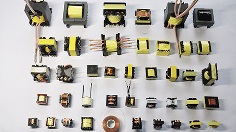
Single-phase transformers operate based on Faraday's law of induction. This law states that a changing magnetic field induces an electric current in a conductor. In a transformer, the alternating current in the primary winding generates a changing magnetic field. This field then induces an alternating current in the secondary winding. The number of turns in the windings determines the output voltage.
AS/NZS 61558.1:2018
Safety of Power Transformers, Power Supplies, Reactors and Similar Products.
AS/NZS 61558.1:2018 is a safety standard that applies to various types of dry-type transformers, power supply units (including switch mode power supply units), reactors, and their combinations. It specifically focuses on stationary or portable equipment that operates independently or in association with each other. The standard covers both encapsulated and non-encapsulated windings.
Key components of a single-phase transformer
- Core: The core is the material that the windings are wrapped around. It is typically made of laminated steel to minimise energy losses and provide a path for the magnetic flux generated by the windings.
- Primary Winding: The windings are the coils of wire that are wrapped around the core. The primary winding is connected to the input voltage source and receives the electrical power.
- Secondary Winding: The secondary winding receives the induced current from the magnetic field and delivers the transformed output voltage.
- Insulation: Insulators prevent the flow of current between the windings and the core.
- Varnish is used to protect the windings and the core from moisture and corrosion.
Step-Up and Step-Down Transformers
- A step-up transformer increases the input voltage to a higher output voltage. It has more turns in the secondary winding than in the primary winding, resulting in voltage amplification.
- Conversely, a step-down transformer decreases the input voltage to a lower output voltage. It has fewer turns in the secondary winding than in the primary winding, resulting in voltage reduction.
Winding Configurations
Different kinds of winding configurations are used in transformers to meet specific application requirements and achieve desired electrical characteristics.
Reasons for using different winding configurations include:
- Voltage Transformation: Transformers are primarily used for voltage transformation, where the primary winding is connected to the input voltage source, and the secondary winding delivers the desired output voltage. The winding configuration is selected to achieve the desired voltage transformation ratio.
- Power Transfer: Transformers are designed to efficiently transfer electrical power from the primary winding to the secondary winding. The winding configuration, such as the number of turns and their arrangement, is optimized to minimise power losses and maximize power transfer efficiency.
- Isolation and Safety: Transformers can provide electrical isolation between the input and output sides, which is crucial for safety purposes. By using separate windings or insulated sections, transformers can ensure that there is no direct electrical connection between the primary and secondary circuits, preventing the transmission of faults or voltage spikes.
- Step-Up or Step-Down Voltage: Different winding configurations allow transformers to step up or step-down voltages. For example, a transformer with more turns on the secondary winding than the primary winding will step up the voltage, while a transformer with fewer turns on the secondary winding will step down the voltage.
- Tap Selection: Transformers may have taps or additional connections along the windings to allow for voltage adjustments. This can be useful in applications where variations in input voltage or specific output voltage levels are required.
The main types of winding you will probably come across are the:
- Double Wound Transformer: A double wound transformer, also known as a two-winding transformer, is a type of transformer that has two separate windings: primary winding and secondary winding. The primary winding is connected to the input power source, while the secondary winding is connected to the load or the output. The purpose of the double winding design is to step up or step down the voltage and/or current levels according to the specific requirements of the application. It enables the efficient transfer of electrical energy from the primary side to the secondary side with a desired voltage transformation ratio.
- Auto Transformer: An auto transformer is a type of transformer that consists of a single winding that acts as both the primary and secondary winding. It has a common portion that is shared by both the input and output sides. The auto transformer is designed to provide voltage transformation by tapping different points along the winding to achieve the desired voltage ratio. Unlike the double wound transformer, the auto transformer does not provide electrical isolation between the input and output. It is commonly used in applications where a small voltage adjustment is required, such as in voltage regulation or as a voltage converter.
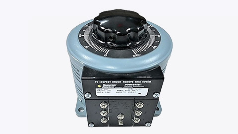
- Instrument Transformer: An instrument transformer is a type of transformer specifically designed for measuring and protecting electrical systems. It is used in conjunction with various instruments and devices to accurately measure high voltage and high current levels. Instrument transformers are primarily of two types:
- Current Transformers: used to step down high currents to a safe and measurable level.
- Voltage Transformers or Potential Transformers: used to step down high voltages to a safe and measurable level.
Transformer Designs
Several designs of single-phase transformers are found in electrical systems according to their intended purposes and specific voltage requirements.
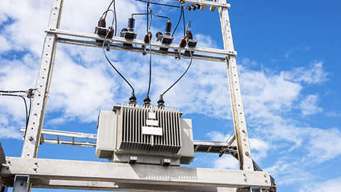
- Distribution Transformers are widely used in electrical distribution networks to transfer electrical power from the transmission system to consumer premises. They typically operate at lower voltage levels and are responsible for stepping down the voltage for domestic and commercial use. Distribution transformers are found on utility poles, in substations, and various industrial settings.
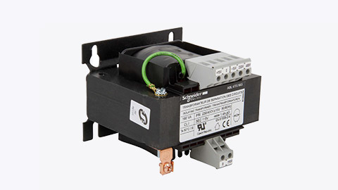
- Isolation Transformers are primarily used to provide electrical isolation and safety in sensitive electronic and medical equipment. They are designed to separate the input and output circuits electrically while maintaining the same voltage level. Isolation transformers protect equipment from electrical noise, voltage spikes, and ground potential differences.
- Autotransformers as previously mentioned have a single winding that serves as both the primary and secondary winding, making them more compact and cost-effective than traditional transformers. (The "auto" in autotransformer refers to the single coil acting alone, not any automatic mechanism.) The autotransformer has electrical connection points called taps. Each tap corresponds to a different voltage, allowing a portion of the winding to act as both the primary and secondary winding. Unlike traditional transformers, autotransformers do not provide electrical isolation between the input and output circuits.
Autotransformers are commonly used for voltage conversion in appliances, lighting systems, and motors when a small voltage adjustment is needed.
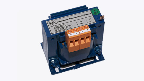
- Control Transformers are used to supply power to control circuits in machinery and equipment. They provide a consistent and stable voltage output for operating control devices such as relays, contactors, timers, and solenoids. Control transformers are commonly found in industrial automation, HVAC systems, and motor control centres. A control transformer is specifically designed to step down the voltage and power the control devices of a circuit or machine. This reduced voltage creates a safer environment for technicians working on the equipment. Control transformers are typically used in electronic circuits that require constant voltage or constant current with a low power rating. Various filtering devices, like capacitors, are employed to minimise output variations and ensure a more constant voltage or current.
- Toroidal Transformers are compact and efficient transformers that use a toroidal (doughnut-shaped) core. They have improved magnetic coupling and reduced electromagnetic interference compared to traditional transformers with laminated cores. Toroidal transformers are commonly used in audio equipment, telecommunications, and renewable energy systems. A toroidal transformer has a core shaped like a donut, and both the primary and secondary windings are wound around the entire surface of the core, with insulation in between. This design helps minimise magnetic flux leakage and makes the toroidal core the preferred choice for transformer construction. Toroidal transformers offer several advantages over traditional square or rectangular transformers. They are highly efficient, operate quietly, generate minimal heat, and have a compact size. These transformers are commonly found in power supply systems, audio systems, control equipment, power inverters, and various other electronic devices. They are especially suitable for sensitive and critical electronic circuits.

Activity
Test your knowledge by answering the questions on this worksheet. Take your answers to class and check with your classmates and tutor.

What we're covering:
- Transformer selection
- Transformer ratings
- Nameplates
- Load capacity
Transformers are available in multiple designs, specifications, and sizes. Selecting the proper transformer for an application requires careful consideration of several factors, such as voltage, current, type of load, efficiency, environment, and cost.
Transformer ratings and load capacity are important factors to consider when selecting a transformer for a specific application.
Transformer ratings
KVA (Kilovolt-Ampere) is a measure of apparent power. It combines both the actual power used (kW) and the power needed to support certain electrical components (reactive power). In a 100% efficient system kW = kVA. However electrical systems are never 100% efficient and therefore not all of the systems apparent power is being used for useful work output.
KVA is a measure of the product of the voltage and current in the transformer.
KVA RATING FOR SINGLE PHASE TRANSFORMER: P = (V X I)/1000
(When applying the formula, always use voltage and current readings from the same side of the transformer.)
Transformers are usually specified in KVA or VA (Volt-Ampere) ratings, e.g., a transformer with a KVA rating of 500 can handle a maximum load of 500,000 VA or 500 kVA.
- Primary Voltage and Secondary Voltage: These values indicate the input and output voltage levels respectively, based on the transformer's turns ratio. The primary voltage is the voltage applied to the primary winding, while the secondary voltage is the voltage output from the secondary winding. Example: A transformer with a primary voltage rating of 480V and a secondary voltage rating of 240V is designed to step down the voltage from 480V to 240V.
- Current Rating: Defines the maximum current that the transformer can safely carry without exceeding its thermal limits. It is expressed in amperes (A) or kiloamperes (kA). Example: A transformer with a current rating of 1000A can handle a maximum current flow of 1000 amperes.
- Frequency Rating: Specifies the nominal frequency at which the transformer operates. The most common frequencies are 50 or 60 Hertz (Hz), depending on the region. Specialized transformers may have different frequency ratings for specific applications.
- Impedance Rating: Represents the total impedance offered by the transformer to the flow of current. It is expressed as a percentage and indicates the transformer's ability to withstand short-circuit conditions. A lower impedance rating indicates a higher short-circuit current capability.
- Efficiency Rating: Indicates the efficiency of the transformer in converting electrical power from the input side to the output side. It is expressed as a percentage and represents the ratio of output power to input power, taking into account losses in the transformer.
Nameplate Rating of a Transformer
The data on the nameplate of a transformer provides important information about its size and capabilities. It includes the transformer's rated kVA (apparent power) indicating its capacity to deliver power to the load continuously. The nameplate also specifies the voltage rating, frequency, number of phases, temperature rating, type of cooling, percentage impedance and reactance, manufacturer's name, and year of manufacture. The nameplate may have multiple voltage ratings depending on the different windings of the transformer. Always check the information on the nameplate before carrying out work involving a transformer.
Watch this video discussing transformer ratings and markings.
Activity
Select the correct answer to the questions using the picture below.
Transformer load capacity
Transformer load capacity refers to the maximum voltage or current that a transformer can safely handle. It is determined by the transformer's design, including its power rating, voltage rating, and current rating. The power rating is calculated based on the temperature rise caused by losses in the transformer. Effective cooling systems can increase the load capacity.
Load capacity is typically expressed in KVA or VA and is important for selecting the right transformer. Transformers have nameplates with information about power capacity, voltage ratios, current limits, frequency compatibility, impedance, and efficiency. Different load capacities, such as 15 kVA, 30 kVA, 45 kVA, etc., are available to meet various needs. The load capacity depends on the voltage and current ratings.
Calculating the transformer load involves understanding the power requirements of appliances and choosing the appropriate transformer size. Full load represents the maximum current that can be transmitted, while the safe load is typically 75-80% of the maximum current and indicates the permissible load.
The transformer load calculation uses the output voltage and current to determine the power in kilovolt-amperes (kVA). Apparent power is calculated from the input voltage and current and then divided by 0.8 to determine the transformer's power rating.
Example
Calculate the rated power of a single-phase transformer with a load voltage of 24 V and a maximum load phase current of 5 A.
The VA rating of the transformer
= V × I
= 24 × 5
= 120 VA
Dividing the VA by 0.8, the revised VA = 150
Choose a transformer with a VA rating of approximately 150 for the load.
Activity
Answer the questions on this worksheet and email your answers to your tutor.
Activity
Carry out some research on the use of oil as an insulator in transformers and answer the following questions. Email your findings to your tutor.
- What is the role of an insulator in a transformer, and why is it necessary?
- What are the properties of oil that make it suitable for insulation?
- Are there any alternative insulating materials used in transformers? If yes, what are they, and how do they compare to oil?
- Are there any safety considerations or environmental impacts associated with the use of oil in transformers?
- Provide examples of practical applications where oil-insulated transformers are commonly used.
