In this topic we’ll:
- introduce landscape graphics symbols used in concept and proposal drawings
- describe some strategies to help “sell” the concept
- explain how to colour-in your concept plan
- describes the steps involved in drawing the concept plan.
By the end of this topic you’ll be able to:
- Draw up your concept plan ready to submit it to your client.
Before we draw our concept plan as part of the design process, it is worth looking at the graphic symbols we need to use. The ones with an * were covered in Site Analysis.
| Object | Description |
|---|---|
| Building wall* | Commonly drawn 2mm wide at 1:100 scale. |
| Window* | The line running the length of the window represents the glass window pane. Where the window has multiple ‘bays,’ divide it up into the relevant number, as shown with the double window in the drawing. |
| Door* | The direction of the arc shows which way the door opens (inwards or outwards, left hinge or right hinge). Use a circle template or drawing compass to draw the arc. |
| Sliding door* | The arrow indicates which panel slides and in which direction it slides open. |
| Bifold door* | Make sure the drawing shows the correct direction of opening (which is almost always outwards). |
| Fence* | Fences are usually shown as a thick line up to 1mm thick. |
| Concrete | Stipples (dots) and small triangles are used to represent the aggregate and sand used in the concrete. You only need to show this detailing in a small part of each area of concrete. |
| Paving | Add this to a small part of the paved area. If the paving pattern changes direction, show this too. Measure the size of the pavers and use this measurement in your drawing, e.g. 400x400mm pavers should be drawn as 4x4mm when working on a 1:100 scale. |
| Brick | Add this to a small part of the brick area. Typically bricks are drawn as 1x3mm at a scale of 1:100. If the brick pattern changes direction, show this too. |
| Decking | Add this to a small part of the decking area. Boards are typically shown as 2mm wide at a scale of 1:100. If the decking pattern changes direction, show this too. |
| Existing trees* | There are many different styles of trees. The one shown here is a really simple (and quick!) one to get you started. Use two different pens, e.g. a 0.2mm and a 0.8mm to do the overlapping circles. The dot in the middle shows that this is an existing tree. A cross is used to show proposed trees (you’ll use this later in the programme). |
| New trees | New trees are shown in the same way as existing trees, except we use a small cross to show the proposed planting location instead of a dot to represent the trunk. |
| Garden areas* | A row of joined up lowercase letter “m” is the simplest graphic for planting masses; a good one to get started with. Where it is important to show masses of taller planting, use a different symbol. |
| Hedges | Drawn in a similar way to garden areas but with regular indentations and a dot or cross to show the approximate centre point of each plant. |
| Lawn | Add stipples (dots) using a fine pen. Take your time doing this so they don’t become short lines, they need to stay as dots. You only need to do this for a small part of each lawn area. |
| Entourage | Add in outdoor furniture to help communicate the scale and function of the garden rooms. |
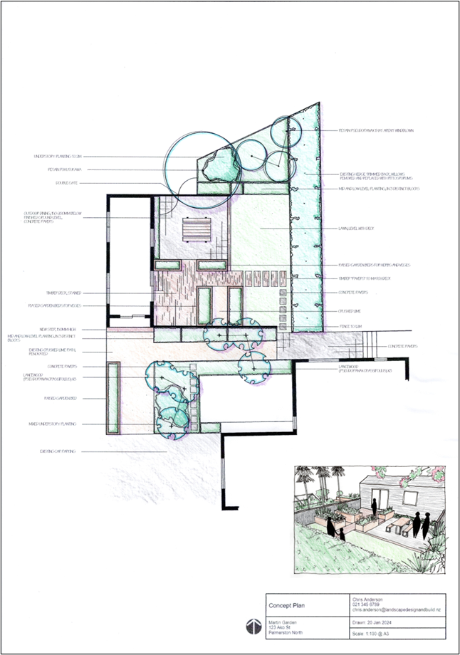
This concept plan for the Martin Garden incorporates most of the landscape graphics symbols. In this plan we’ve opted to use a different tree graphic for the proposed trees.
The concept plan is presented to the client to get their feedback and ultimately their approval to draw up the final proposal. To this end, you need to “sell” them on the concept you are presenting them so that they are excited about the concept and their feedback is for minor changes rather than a complete redesign.
Some things that can help sell your concept are:
- a short written narrative describing what it will be like to be in the garden
- one or more perspective drawings.
Writing a narrative
Use emotive language that plays into the client’s reasons for wanting this new garden.
A narrative could read:
“Enjoy the dappled summer sun on your back as you sit in your beanbag on the lawn under the pohutukawa tree reading your book and sipping tea. Take in the birdsong as you walk to the raised planter boxes to pick a large, ripe tomato and pull off some basil leaves. Pop inside to make lunch, returning shortly after to sit and eat at the outdoor table. The plants rustle in the breeze. You love spending time in your happy place.”
Creating perspective drawings
Because you’ve already created a 3D model of the garden, making a perspective drawing is fairly straightforward. Print a scene or view of the model, trace over it, then render (colour) it in, using the same techniques as for your main plan drawing. We’ll explain this later in this topic.
Using a traced image rather than simply attaching the printout of the 3D model has two main advantages:
- The style of the drawing will be consistent with your main plan drawing.
- The traced image is more abstract and therefore the client is unlikely to become tied to the specifics, as could be the case where you have used identifiable plants in the 3D model.
You may choose to use a ruler to create straight lines, or freehand trace them, as shown below.
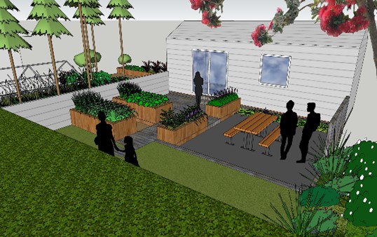 |
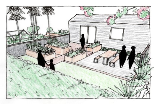 |
| A scene from the 3D model (left) and traced and rendered perspective drawing (right) of the Martin Garden rectilinear design. | |
Rendering means colouring in.
In this programme we are going to use basic or “rough” pencil rendering. This involved using coloured pencils to lightly shade in the different areas using parallel strokes of the pencil. It’s not essential to vary the colouring from light to dark within each shape. It is fine for it to be one colour and intensity.
Watch: Color Pencil Technique - Architecture Daily Sketches
This video (10:05 minutes) by Themodmin provides a good example of the color pencil technique.
Finish your rending by adding shadows. Decide where your light source is coming from. Commonly this is either the top left or top right corner (from the northwest or northeast). Make sure all of the shadows point away from the light source. In the concept plan shown above the light source is at the top left corner of the page so all shadows point down towards the bottom right corner.
An easy, and appealing way to add shadows is by using a purple colouring pencil, as shown in the previous drawing.
The steps to drawing our concept plan are consistent with the steps we’ve used for our other plans, with the addition of rendering our drawings.
The key steps are:
- Add the pencil linework:
- trace those elements from the base plan that you’re going to retain
- draw in the future side of any existing trees
- draw in the elements of the concept design
- add entourage, such as outdoor furniture.
- Add ink lines using the correct graphic symbols and add ink linework for your perspective drawing(s) if required.
- Add annotations for any parts of the concept that need further explanation.
- Add the title block.
- Add your narrative, if required.
- Take a scan or photocopy of your drawing before you render it. This way if you make a mistake you can make another go of the rendering.
- Render it.
Assessment 2
You are now ready to complete Assessment 2: LDB03A2: Produce a concept plan.
Draw up a concept plan for your site so it is ready to submit to your client. You can choose to do one or two concept plans (the minimum is one).
Once you have submitted this assessment, you have made it to the end of this module!
In the next module we’ll work on the last stage of the design process: development of the landscape design proposal.