Practice
Use the PC Building Simulator to practice computer assembly and disassembly, then benchmark different configurations.
Explore
Explore Lessons 1 and 2 of the CompTIA A+ eBooks.Computer hardware is made up of tangible components. These components interact with all 5 of your senses.
But although they are tangible hardware items, the processes that run inside them are intangible.
Computers (i.e. their hardware, software and firmware) require several things to function properly:
- a method to receive
- a method to process data input
- a way to output data
- a way to store data.
(Cyber Pathways Across Maryland, 2016)
Let's discuss them in the following 5 subtopics:
- Receiving data
- Processing data
- Output data
- Store data
- Legacy systems
Receiving data
To receive data input, you generate instructions by clicking, typing, drawing, talking, or performing other actions. The computer processes these instructions through one of the following peripherals:
- a mouse
- a keyboard
- a stylus and a tablet
- a microphone.
The instruction is then translated into a language that the computer understands. Let's have a look at the 3 examples of computer language:
- Binary code
- ASCII
- Extended ASCII
how exactly does Binary code work? (4:40 minutes)
Watch the video below for a succinct overview of how binary code works,
Base 10
The word 'computer' comes from the Greek word compute, meaning to calculate.
Let’s look at how we learn to calculate in school, in base 10 by powers of 10:
101 = 10
102 = 10*10 = 100
103 = 10*10*10 = 1,000
106 = 1,000,000
We count: 0 1 2 3 4 5 6 7 8 9 and then start to combine the single digits:
10
11
15
If someone asks you how old or how young you are, your answer will be based on the base 10 number system you learn in school. Base 10 consists of:
1 for multiples of 10 and
0 to 9 for single digits.
So, if you are 22 years old, the base 10 breakdown will be:
#22
2 x base 10 = 20
2 x single digits = 2
BASE 2
Computers count by base 2:
21 = 2
22 = 2*2 = 4
23 = 2*2*2 = 8
210 = 1,024
220 = 1,048,576
Let’s convert 22 into the digital binary code of 8-bit (lease note in the image above that the final digit in the lower row should be 1 not 0.):

So how do we reach the binary code (above) of 0001 0110 for the decimal number of 22?
Here are the questions that you need to ask to figure out the placements of 1 and 0:
- 128 - Is there 128 in 22? No, so you put 0 in the first 8-bit space.
- 64 - Is there 64 in 22? No, so you put 0 in the next 8-bit space.
- 32- Is there 32 in 22? No, so you put 0 in the next 8-bit space.
- 16 - Is there 16 in 22? Yes, so you put 1 in the next 8-bit space. You will now calculate 22 - 16 = 6.
- 8 - Is there 8 in the remainder (6)? No, so you put 0 in the next 8-bit space.
- 4 - Is there 4 in the remainder (6)? Yes, so you put 1 in the next 8-bit space. You will now calculate 6 - 4 = 2.
- 2 - Is there 2 in the remainder (2)? Yes, so you put 1 in the next 8-bit space. You will now calculate 2 - 2 = 0.
- 0 - There’s no more number to deduct, and you put 0 at the end.
Binary code in digital computers
The binary code is a code used in digital computers, based on a binary number system in which there are only 2 possible states: off and on. This is usually symbolised by 0 and 1.
A binary code signal is a series of electrical pulses that represent numbers, characters and operations to be performed. An internal device (called a 'clock') sends out regular pulses, and components (such as transistors) switch on (1) or off (0) to pass or block the pulses. (adapted from Britannica, 2022)
BIT stands for a BInary digiT.
There are 8 bits in 1 BYTE.
Watch - how transistors work (4:54 minutes)
The following video explains how the binary code is reproduced by a flick of a switch in a transistor.
ASCII
ASCII (American Standard Code for Information Interchange) is a standard data-transmission code used by smaller and less powerful computers to represent textual data (letters, numbers and punctuation marks) and noninput-device commands (control characters).
ASCII converts information into standardised digital formats that allow computers to receive, process, output and store data.
The initial application of this code was for teletypewriters but eventually found wide application in personal computers.
The standard ASCII code uses 7-digit binary numbers, which result in 128 different possible combinations of 7 of either 0 and/or 1.
The following table shows the conversion from the Roman alphabetical letters of A-D to an ASCII code to a binary.
| Letter | ASCII Code | Binary |
|---|---|---|
| A | 065 | 01000001 |
| B | 066 | 01000010 |
| C | 067 | 01000011 |
| D | 068 | 01000100 |
You can view the full conversion chart through this link.
Converting numbers into binary for beginners (10:26 minutes)
Let’s have a look at how the binary code is used in the ASCII system in the following video.
Extended ASCII code
Digital computers use 8-bit bytes--a binary code arranged in groups of 8 rather than 7 digits or bits.
The extended ASCII code is embedded in an 8-bit field consisting of the 7 information bits and a parity bit to check for errors or represent certain symbols.
The 8-bit system expanded the number of characters represented from 128 to 256. The 8-bit system, known as the 'extended ASCII code', was introduced by IBM (International Business Machines) Corporation in its first personal computer model in 1981.

This extended ASCII code has since become the industry-wide standard for personal computers.
So what do the 256 characters consist of?
Here's a breakdown:
- The first 8 bit of the 32 code combinations are used for machine and control commands.
- The second 8 bit of the 32 combinations is used for numbers and various punctuation symbols.
- The third 8 bit of the 32 combinations are used for uppercase letters and a few other punctuation marks.
- The last 8 bit of the 32 combinations is used for lowercase letters.
You can view the extended ASCII conversion chart through this link here.
Processing data
Once data is received through one of the peripherals, it will be processed by a component inside your processing unit.
Let's have a closer look at the major components inside a typical desktop computer system.
Major components of a desktop computer
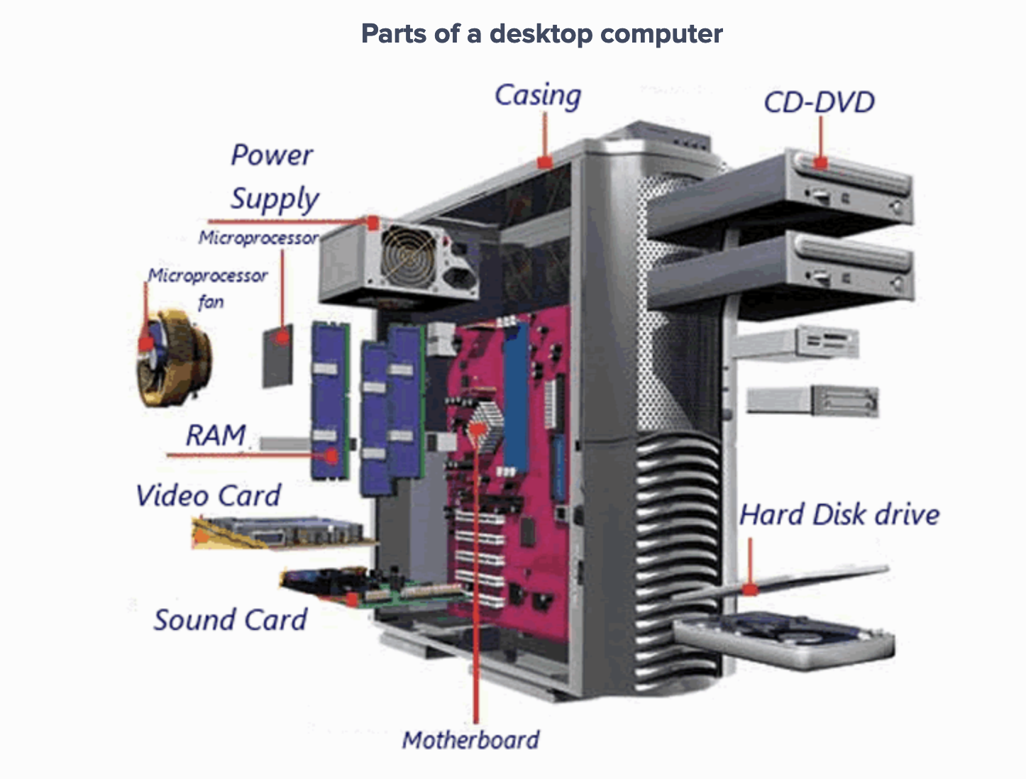
Source: https://www.easypacelearning.com/
You will likely have the following components as part of your desktop computer:
- processor
- motherboard
- case
- expansion
- power supply system
- storage
How do components talk to each other?
The previous diagram describes the major components inside a computer, but how do they communicate with each other?
watch - computer basics: inside a computer (2:17 minutes)
The following short video introduces computer components and how they communicate with each other.
Tiny, yet powerful, transistors
We have looked at the circuit board in the previous video--one of the components within this circuit board is the 'transistor'.
A transistor is a semiconductor device used to amplify, control and generate electrical signals.
Transistors have active components that consist of integrated circuits or microchips. These components often contain billions of minuscule devices etched into their shiny surfaces.
The 3 typical leads in a transistor are the emitter, the collector and the base (or, in modern switching applications as illustrated below: the source, the drain and the gate).
The electrical pulses we see progressing through the components have to go through these transistors.
The previous image shows how negative-channel metal-oxide semiconductors (NMOS) employ a positive secondary voltage to switch a shallow layer of p-type semiconductor material below the gate into n-type. For positive-channel metal-oxide semiconductors (PMOS), all these polarities are reversed.
WATCH - from sand to silicon: the making of a microchip (4.44 minutes)
Watch the following video from Intel on how tiny, yet powerful, transistors are made.
Output data
Data processed through the major components will be sent to one of these output systems:
- screen displays - monitors, projectors, etc.
- printers - laser, inkjet, thermal, 3D, etc.
- audio - headphones, speakers, etc.
Store data
Data can also be permanently stored in one of these storage data options:
- internal or external
- solid-state
- mechanical.
Computer storage and memory are often measured in megabytes (MB) and gigabytes (GB). A medium-sized novel contains about 1 MB of information. Take note that computer binary code use binary (base 2) math, instead of a decimal (base 10) system.
The following table provides examples of the size and capacity of standard storage units.
| Unit | Equivalent |
|---|---|
| 1 kilobyte (KB) | 1,024 bytes |
| Not one thousand bytes as might be expected, because computers use binary (base two) math, instead of a decimal (base ten) system | |
| 1 megabyte (MB) | 1,048,576 bytes |
| 1,048,576 (1024x1024) bytes, not one million bytes A medium-sized novel contains about 1 MB of information |
|
| 1 gigabyte (GB) | 1,073,741,824 bytes |
| 1,073,741,824 (1024x1024x1024) bytes. | |
| A mobile plan of 1GB allows you to browse the web and check your email for up to around 40 minutes per day | |
| 1 terabyte (TB) | 1,099,511,627,776 bytes |
| Equates to about the same amount of information as all of the books in a large library, or 250 of 2 hours long HD movies | |
| 1 petabyte (PB) | 1,125,899,906,842,624 bytes |
| Extremely large unit of digital data, an estimate of 20 million tall filing cabinets or 500 billion pages of standard printed text. |
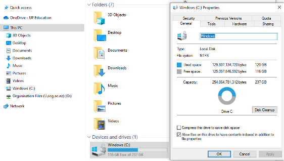
So, how do you check your computer system and storage capacity?
The following screenshots look at a Windows 10 system.
Under Search - type ‘This PC’.
To look up System type, right-click on This PC > Properties.
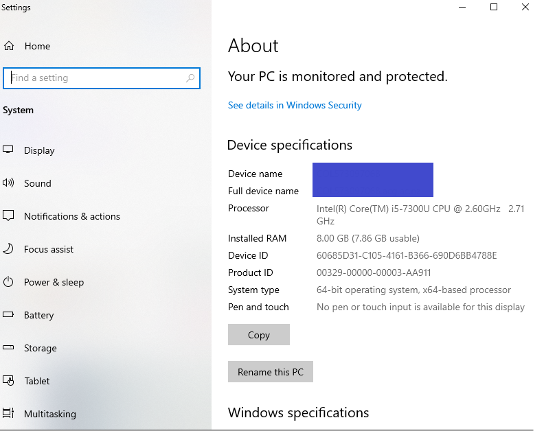
To look up Device capacity, select This PC > Devices and drives.
Legacy systems
The number of transistors in a dense integrated circuit (IC) doubles about every two yearsMoore's law
According to Synopsys (software company), the origin of Moore's Law was originally derived from an observation by Gordon Moore, the co-founder of Fairchild Semiconductor and later the co-founder and CEO of Intel.
In 1965, Moore wrote that the number of components in a dense integrated circuit (i.e. transistors, resistors, diodes or capacitors) had been doubling with every year of research. He predicted that this would continue for another decade.
Later, in 1975, he revised his prediction to the doubling occurring every 2 years.
The following chart from Our World in Data helps plot out the predictions of Moore's Law versus real-world data (note that the Y-Axis is logarithmic).
So, what does this mean for IT Technicians?
As an emerging workforce in the tech industry, you will be working with legacy systems--systems that are now defunct or no longer being updated.
The legacy system applies to transistors and other components within computer systems.
It is important that you know the basics of how these components work and are able to transfer and update your skills and knowledge on the latest technology.
What you see is what you get with hardware - if you can see and touch it then it is hardware. Within those devices that sit on or under desk are a number of components that make it work. The focus of this section is what goes inside different devices.
The key components across all devices are very similar. There must be something to connect the processor to other components for storage, input, and output. This "backbone connector" is the motherboard. The things connected are a processor to make it all work, storage for the data, and a way to input and output the data. In this section going to look at major components in common devices. These same components are found in other IT devices such as those devices used in CCTV (Closed Circuit TV) and VoIP (Voice over IP) systems.

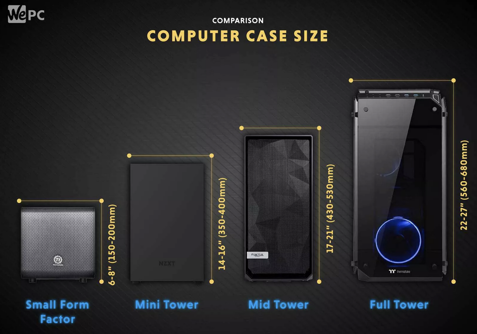
In this subtopic, we will look at the external component that houses all of the internal components of our computer.
The computer case is the largest external component. Its specific functions are to:
- act as a protection and barrier from unwanted elements such as dust, water, etc.
- house and provide structure and layout for the internal components
- allow movability and safety when relocation is needed (note that you must ensure that your computer is turned off before moving it, or you will risk damaging data storage)
- provide portability (an option to consider when deciding on the type of case to use).
The following image provides a size and component comparison between the 4 typical desktop case models.
| Full Tower | Mid Tower | Mini Tower | Smaller Form Factor | |
|---|---|---|---|---|
| Motherboards | Mini-ITX MicroATX ATX EATX |
Mini-ITX MicroATX ATX |
Mini-ITX MicroATX |
Mini-ITX |
| 5.25″ Drive Bays | 3-6 | 2-5 | 1-2 | 1 |
| 3.5″ Drive Bays | 6-13 | 6-7 | 4-6 | 1-3 |
| 2.5″ Drive Bays | 0-10 | 0-6 | 0-4 | 0-2 |
| Expansion Slot | 7+ | 5-7 | 4 | 2 |
| Graphics Cards | 3-4 | 2-3 | 1-2 | 1 |
| Case Fans | 8+ | 3-8 | 2-4 | 1-3 |
As you can see from the previous table, the small size and portability of a smaller form factor and mini-tower can be a winning factor for buyers who value the compact and straightforward functionality.
However, clients that require more customised and powerful features would require the space to insert larger and more specific components.
The following image illustrates the various external aspects of a standard case.

- power supply
- chassis fan outflow
- motherboard I/O panel
- expansion card slot (in use)
- expansion card slot (not in use)
- optical drive
- unused optical drive
- front I/O panel (audio and USB)
- temperature display
- power button
- fan vents for airflow
Activity - Laptop or desktop computer?
Let’s look at a few different scenarios and assist these customers with their desktop case or laptop options.
- Nellie is running a new business from home and would like a compact computer that allows her to run most of the Microsoft Office products, browse the internet and contact her clients. The new computer will be placed in the home office and shouldn’t take too much space on the new work desk.
- Dan is starting a new design course and is required to work on his assignments from both home and campus. He will be using the Adobe Creative suite to complete his design work.
- Andy is an avid gamer and is upgrading his computer to be able to do not only 3D modelling, but also 3D rendering. He will be using Autodesk programmes to do this.
Share your thoughts on the initial decision-making process of choosing the appropriate desktop case or laptop options with your Hardware Task Forum group, or with your tutor in the Live Session.

The motherboard is the central component of the computer. The CPU (processor), memory and storage (hard drives) are directly connected to the motherboard.
If you open a PC case and take a look inside, the motherboard will be the large circuit board in the middle that everything else is connected to.
A computer's motherboard is commonly mounted on standoffs and positioned with its IO (input/output) at the rear of the case.
Some PC manufacturers (e.g. HP, Dell and Lenovo) design and create their motherboards; while others will use motherboards designed by other vendors (such as Acer, ASRock, ASUSTek, Biostar, EVGA, Corporation, Gigabyte, Intel, MSI, Shuttle, Tyan and Via).
Form factor

PC cases are usually designed to accommodate one of the specific motherboard form factors described below.
| Form Factor | Description |
|---|---|
| ATX | The Advanced Technology Extended (ATX) specification was developed by Intel in 1995 to provide a new design for PC motherboards, updating the previous AT form factor. Full-size ATX boards are 305x244mm. ATX boards can contain up to 7 expansion slots. |
| Micro-ATX | The Micro-ATX (mATX) standard is for a 244x244mm square board. mATX boards can accommodate fewer expansion slots with a maximum of 4. |
| Mini-ITX | The Mini-ITX standard specifies a board size of a 170x170mm square board. Mini-ITX boards can only accommodate 1 expansion slot and are suitable for small form factor PCs. |
As well as physical dimensions, each form factor will also share common placement of other components (like CPU, RAM and power or storage connector) making PC building easier and more predictable.
The image below illustrates the generic components found on a motherboard.

- PCI slot
- PCIe slot x16
- PCIe slot x1
- north bridge
- CPU socket
- external ports
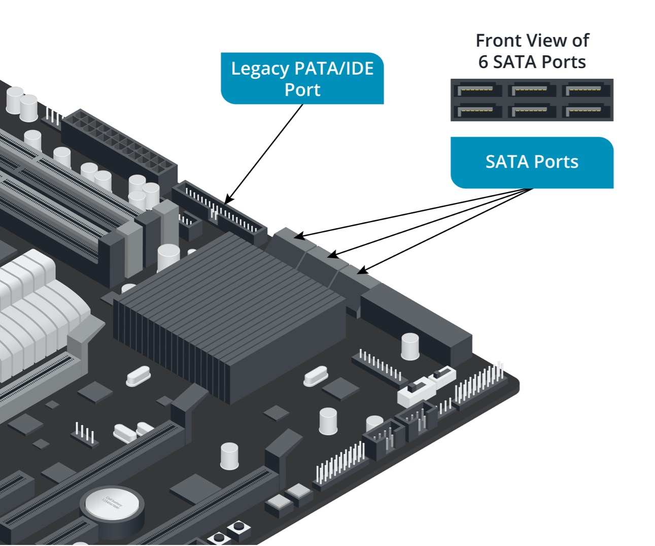
- SATA ports
- south bridge
- memory slots
- power connector
PCIe Slots are always positioned to align with expansion slots on the back of the case. The external IO ports are located at the top left of the board. An IO shield is usually included with each motherboard, specific to each motherboard, to prevent dust and improve electrostatic discharge (ESD) protection.
BIOS/UEFI
BIOS
A Basic Input/Output System (BIOS) lives on a chip on a motherboard and provides a way of interacting with the computer hardware, before the operating system loads.
Common BIOS settings include:
- boot order – the order you want the computer to look for a bootable drive
- power options – whether you want the computer to restart after a power failure
- fan settings – speed and cut-off
- overclocking – CUP multiplier and voltage, memory timing.
UEFI
Most motherboards now use the Unified Extended Firmware Interface (UEFI), which replaces the traditional BIOS.
UEFI has many of the same features as a BIOS with the inclusion of more addressable space--allowing UEFI to feel more like a tiny operating system, and security features like Secure Boot to protect prevent malicious tampering of the boot process.
CPU Cache
The CPU cache is used by the CPU of a computer device to allow you to access information in a faster manner compared to accessing information from your main hard drive. The benefit is improved efficiency in data retrieval.
System bus
Buses within a computer device are high-speed connections used to send signals that connect all internal components (see illustration below).

There are 3 types of buses used:
- Control bus
- Data bus
- Address bus.
The term 'system bus' is used when these 3 buses are together.
The buses can be explained as 'wires on a track circuit'.
Data bus
Like its name, the data bus transfers data and instructions between components within the motherboard. The data bus is bi-directional as it can travel to and from the memory.
Control bus
The control bus is bi-directional, it sends control signals between components within the computer device.
Address bus
An address bus sends single directional signals from the CPU to the main memory. It will send instructions but only goes from the CPU out.
watch - computer architecture- system bus (4:04 minutes)
For further information on the different types of buses and how they work together, watch the following video.

The central processing unit (CPU) is what a computer uses to execute program instructions and perform calculations. It is often described as the 'brain' of the computer.
Over years of development, CPUs have become faster and more capable, integrating new architectures and manufacturing techniques to reduce the size and increase efficiency.
Until a few years ago, CPUs were designed to run 32-bit code. This means that each instruction can be up to 32-bits in length. A 32-bit CPU's General Purpose (GP) registers are also 32-bits wide. However, since 2004, most desktop CPUs (and from 2006, most laptop CPUs) released to the market have been capable of running 64-bit code.
Initially, there were only two major manufacturers of computer processors: Intel and AMD. Between 2005 and 2022, Intel was supplying processors to Apple. Apple had previously been using chips supplied by Motorola and is now designing and manufacturing their own chips for their desktop, laptop and mobile product lines.
Intel and AMD remain the only significant suppliers of CPUs for PCs.
watch - how a cpu works in 100 seconds (12:44 minutes)
Learn more about CPUs by watching this next video.
Operation

The basic operation of a computer is to fetch instructions from the main memory and execute them. There is a 3-stage cycle (see the diagram above) that occurs to deliver and action instructions.
- Fetch: collects the program command from the computer memory.
- Decode: deciphers what the program is telling the computer to do.
- Execute: carries out the requested instruction.
To ensure your computer device is processing data and instructions efficiently, it will need to travel through each of these stages.
Clock speed
Manufacturers use several metrics to describe the performance of their CPUs. 'Clock speed' describes the speed at which the CPU runs.
When comparing CPUs of similar architecture and generation, a higher clock speed will generally indicate a more performant CPU.
Clock speed is now usually measured in gigahertz (GHz), with most CPUs measuring somewhere between 3 and 5ghz.
Overclocking
The term 'overclocking' refers to the process of pushing components past the manufacturer's specified optimum rating.
Manufacturers set the clock speed of CPUs to balance performance, reliability and the likelihood of damage. Some CPUs are unlocked by manufacturers, allowing their core clock speed to be increased by adjusting the clock speed multiplier.
Overclocking puts more strain on a CPU and without adequate cooling can cause damage and decrease its reliability and lifespan.
So why do it? Overclocking is generally performed by hobbyists and games enthusiasts but it is also a means to build a PC more cheaply by specifying lower-cost components, then boosting their performance.
Hyperthreading
'Hyperthreading' is a CPU used to create more efficient scheduling of the work done by the processing cores that you have.
For more information on hyperthreading and the benefits, check out this video.
Multi-core processors
Another metric used to describe the performance of modern CPUs is the number of cores and threads.
Multi-core CPUs combine 2 or more CPUs into a single package, increasing the number of instructions or calculations that can be executed for software that is designed to take advantage of them.
Intel's current (12th generation) core series processors often have 6 or more cores.
AMD's processes often have a higher core count with their flagship Threadripper having up to 128 cores and many of their most popular options having 24 or 32 cores.

Socket
A CPU is mounted to a motherboard in a special socket that makes contact with hundreds of pins.
Intel CPUs use a Land Grid Array (LGA) form factor. The CPU package has a flat bottom with flat contact pads. The socket contains tiny pins for making contact.
The LGA form factor reduces the risk of damage to the CPU; however, increases the possibility of damage to the motherboard.
AMD CPUs use a Pin Grid Array (PGA) form factor. Each CPU package includes hundreds of tiny pins designed to correspond to the socket on the motherboard.
Care must be taken to orient the CPU correctly with the socket and to insert it so as not to bend or break any of the pins.
Cooling
Computers generate heat. Adequate cooling is important for a CPU's smooth operation and longevity.
Heatsink
A heatsink is a passive cooling device that uses highly conductive materials to move heat away from a source, allowing the surrounding air to cool it.
CPU cooling solutions often involve the use of specially designed heatsinks that incorporate special heat pipes and fins to increase their efficiency. To aid the transfer of heat from the CPU to the heatsink, thermal paste is applied to the surface of the CPU.

Fan
Fans (see above) are also used to increase cooling efficiency, by generating a higher amount of airflow over the heatsink.
Modern CPU fans use either a 3- or 4-pin connector.
The 3-pin fans can vary fan speed using voltage; however, it is more likely they are either on or off in response to a particular temperature threshold.
A 4-pin fan uses Pulse Width Modulation (PWM) to vary fan speed. PWM provides greater control over fan speed, helping to reduce noise by allowing fans to spin at slower speeds when the CPU is under lighter loads.
Water cooling
Some high-end gaming PCs utilising multiple graphics or overclocked hardware can produce more heat when under load. This can be adequately dispersed by a traditional heatsink and fan cooling system.
Liquid-based cooling solutions use water blocks in place of heatsinks and small pumps in place of fans. Water is a much more efficient coolant than air.
On the downside, liquid-based cooling systems can make it more difficult to upgrade and repair a PC and care must be taken to avoid leaks and liquid damage to internal components.

System memory is a form of 'volatile' memory (meaning that data stored in it is lost when the power supply is off) called Random Access Memory (RAM).
RAM is used by the system to temporarily store the operating system and applications, giving the system faster access to the data and therefore making the system run faster.
The more RAM a system has the less often it needs to fetch or write data to and from its mass storage devices.

Over the years, the type of RAM used in computer systems has increased in size and speed.
- During the 80s--having a few kilobytes (KB) of RAM was more than adequate.
- In the 90s to early-2000s--having a couple of hundred megabytes (MB) would have been more than okay.
- Today--it is uncommon to see new computers with less than 8 gigabytes (GB) of RAM, and systems with 32, 64 or even 128GB of RAM available for purchase.
Upgrading and increasing the amount of RAM a system has is often one of the easiest and most cost-effective performance improvements you can make.
Types of RAM
SDRAM
Synchronous DRAM (SDRAM) is a type of dynamic RAM that was common in computers from the mid-90s.
DDR-SDRAM
Double Data Rate SDRAM (DDR SDRAM) is what you will find in most modern computers. It was released in 2001 and has been improved and updated over the years to increase clock speed and transfer rate.
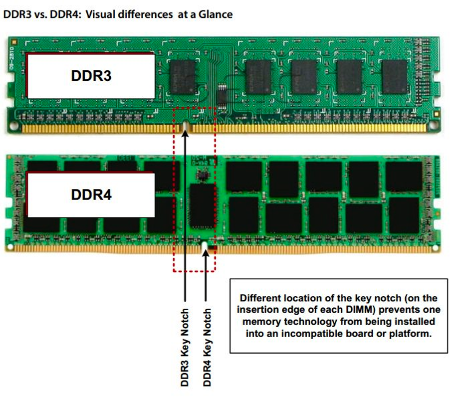
The current generation of DDR SDRAM is DDR4 which has been in use since 2014. If you are working on an older system you may find they are using DDR3.
Memory modules
A RAM module, or memory module, is a printed circuit board that holds a group of memory chips that act as a single unit. These modules are often referred to as DIMMs (dual inline memory modules). DIMMs are inserted into slots on the motherboard, and they are removable and replaceable.
DIMMs from different DDR generations may look similar, but they have different numbers of pins and notch (key) positions to prevent them from being incorrectly used or inserted (see the example below).
Laptop RAM modules are smaller and known as Small Outline DIMMs (SODIMM).
Dual-channel memory
Because of speed improvements being made to CUPs during the 2000s, it became evident that RAM speed was hindering computer performance.
Intel and AMD addressed this issue by developing the dual-channel memory architecture.
Traditionally, single-channel memory uses a 64-bit bus for communication between the CPU and RAM. By utilising a dual-channel memory controller, 2 of the 64-bit buses can be combined in a single 128-bit bus, doubling the amount of data that can be moved during each transaction.
Dual-channel is a feature that is supported by the motherboard and does not require a special type of module.
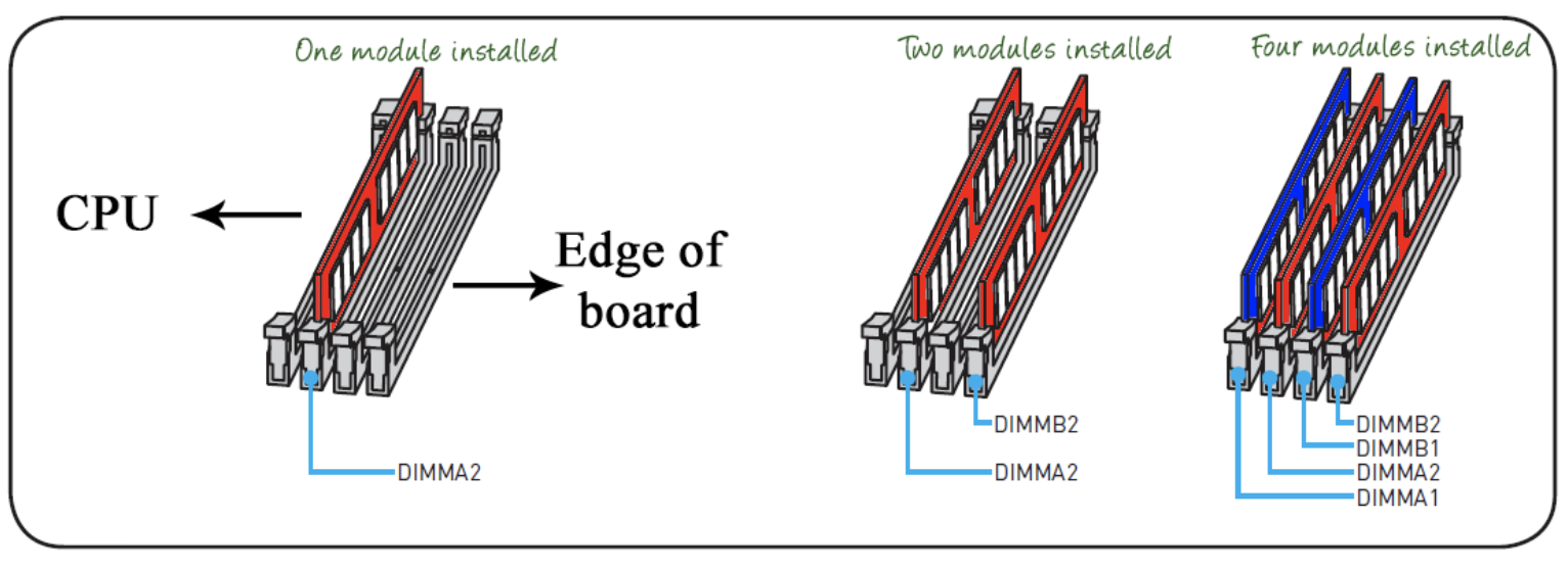
For dual-channel memory to function correctly, DIMMs must be inserted in the correct slots on the motherboard. If a motherboard has 4 RAM slots, they will likely be in colour-coded pairs.
Modules should be inserted into each of the pairs, in the same position (see image below). Each module should have an identical size and speed.
Parity and ECC
Error Checking and Correcting (ECC) RAM is common in servers and workstations where a high level of reliability is required.
ECC RAM includes additional circuitry for the detection and correction of errors. This type of RAM needs to be supported by the motherboard for it to function correctly and is often slower than regular RAM--meaning a slight performance hit for systems that don’t require it.
'Data storage' refers to the storage of information through a device that helps to retain data.
Different types of storage devices can be used to retain information on your computer.
- System memory provides a fast storage medium for the operating system and applications. Data, however, cannot be stored without a power supply.
- Mass storage devices hold data when the system is powered off.
- Removable mass storage devices and removable media allow data to be archived from the PC and transferred between PCs.
- External storage devices are also popular for backup and data transfer or to provide a drive type not available as an internal unit. A device such as an external hard drive would typically be connected to the computer via a USB port.
- Disks are one of the main forms of a physical storage device used to retain information. We'll look at disks in more detail next to learn of the disk types and how they are used to store data.
Types of disks

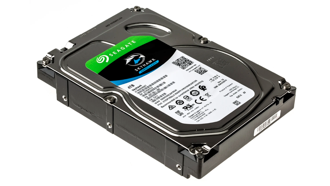
HDD - Hard Disk Drive
Even with the advances in the speed and capacity of other types of storage technology, the hard disk drive (HDD) remains the primary method of persistent storage for PC data.
- On a workstation PC: the hard disk drive will store the operating system files, application program files, system software files (such as drivers), and user data.
- On a server PC: the hard disks will store individual user files and shared sources of information, such as databases.
Advances in hard disk technology have enabled disks of up to 8 terabytes (8,000 GB) to be produced, although smaller capacities are more common for performance and reliability reasons.
HDD characteristics
- Data is stored on several metal or glass platters that are coated with a magnetic substance. The top and bottom of each platter are accessed by its own read/write head, moved by an actuator mechanism.
- The heads do not touch the surface of the platters. The platters are mounted on a spindle and spun at high speed.
- The disk unit is kept sealed to maintain constant air pressure and to prevent the entry of dust.
There are 2 main formats for HDDs:
- 3.5" units are the mainstream format used in PCs
- 2.5" form factors are used for laptops and as portable external drives.
HDDs can also vary in height, with 15mm, 9.5mm, 7mm and 5mm form factors available.

SSD - Solid-State Drive
'Flash memory' is being incorporated onto a new generation of Solid-State Drives (SSDs) designed to replicate or supplement the function of the hard drive.
An SSD might be installed as the computer's only internal drive or as a system drive for use with an additional hard drive. The SSD would normally be used to install the OS and software applications, whereas the HDD would be used for user data files. In this configuration, both drives are available to the user.
Advantages of flash memory-based SSDs
- The lack of moving parts makes them quieter, more power-efficient and less prone to catastrophic failure or damage due to shock (through dropping or moving a device rapidly, for instance).
- Read times are better because seek time, and consequently the effect of file fragmentation, is eliminated.
- They are less susceptible to data loss in the event of power failure.
- Most drives still feature DRAM-based write cache to improve performance.
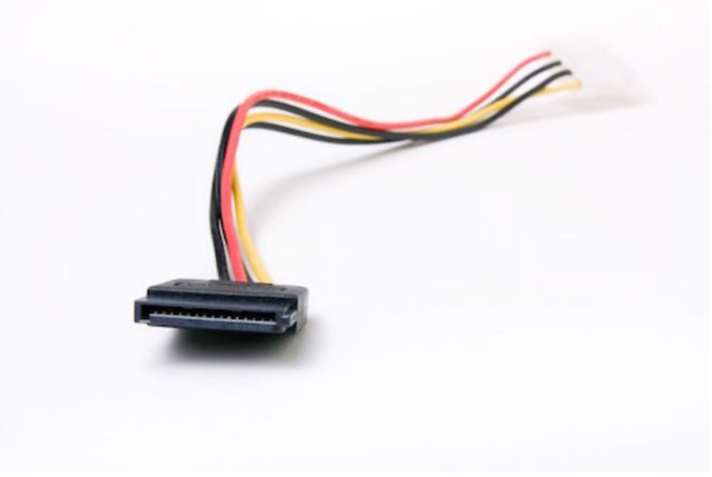
External Devices - SATA, eSATA
Serial Advanced Technology Attachment (SATA) is the standard means of attaching internal storage drives to a desktop PC.
Some of the characteristics are that:
- SATA transfers data in serial format, which allows for thin, flexible cables of up to 1 m (39")
- the cables are terminated with compact 7-pin connectors (each SATA host adapter port supports a single device)
- SATA is a hot-swappable interface, which means that a compatible drive can be connected or disconnected while the system is running.
Optical Drive - CD, DVD, etc.
Optical drives include CD drives, DVD drive, and Blu-Ray drives.
Optical drives are considerably larger than hard disks (5.25" form factor). An internal unit would be installed to a 5.25" drive bay and connected to the motherboard via SATA data and power connectors.
Many optical drives also function as recordable/rewritable CD burners (or writers). An external unit would be connected via USB and typically require their power supply provided via a supplied AC adapter.
A CD drive consists of a spindle motor (to spin the CD), a laser and lens (to read the CD) and a tracking system to move the laser and lens assembly. The mechanism for inserting a CD is either tray- or slot-based. Slot-loading mechanisms have rollers that grab the CD upon inserting.
Legacy devices – floppy
The floppy disk (also known as the flexible disk or simply 'floppy') is a thin, flexible disk that is used to record information.
For more information on how floppy disks are used, view this video.
RAID - Redundant Array of Inexpensive Disks
A Redundant Array of Inexpensive Disks (RAID) can be defined as a virtual disk that combines multiple physical drives into one unit. This can act as a backup and can increase reliability and fault tolerance.
There are 3 reasons why RAID may be used:
- stripping data between multiple disks
- mirroring data between multiple disks
- parity--to rebuild data.
Types of RAID
Different RAID levels exist depending on the purpose and requirements.
The most common levels are numbered from 0 to 6, where each level corresponds to a specific type of fault tolerance. Only levels 0, 1 and 5 are of much relevance on the desktop.
watch - what is raid 0, 1, 5 and 10? (5:04 minutes)
Watch the following video about RAID levels.
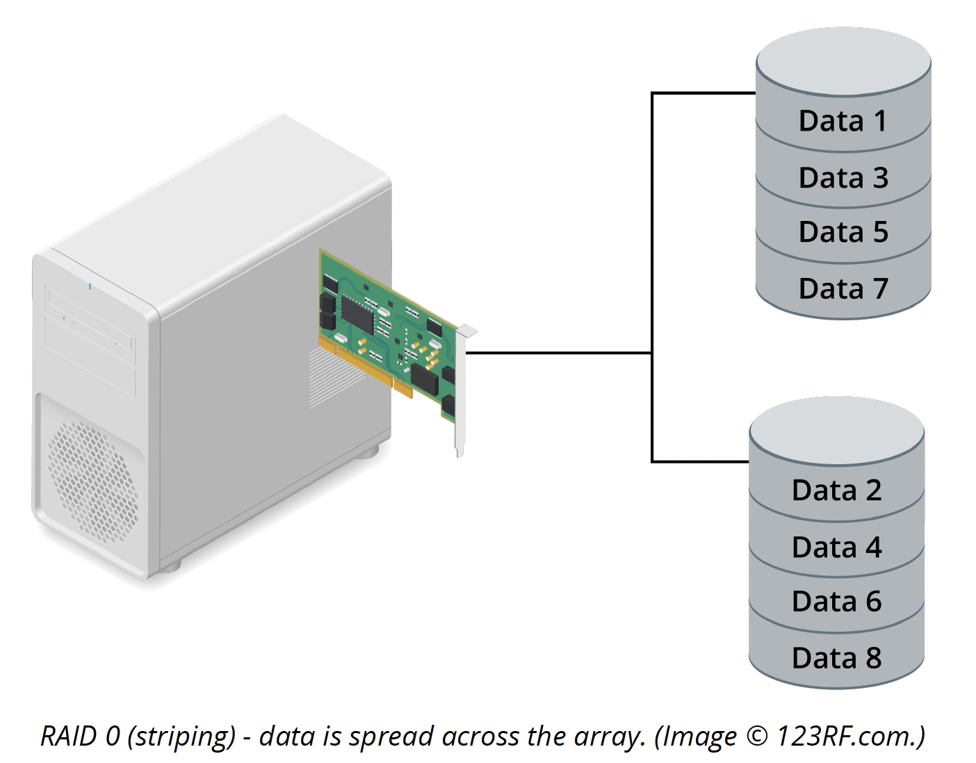
RAID 0
Disk striping is a technique where data is divided into blocks and spread in a fixed order among all the disks in the array. RAID 0 requires at least 2 disks (see below).
RAID 1
Mirroring requires 2 hard disks. The mirror disk is a duplicate of the data disk (see below). Each write operation is duplicated on the second disk in the set, introducing a small performance overhead. A read operation can use either disk, boosting performance somewhat.
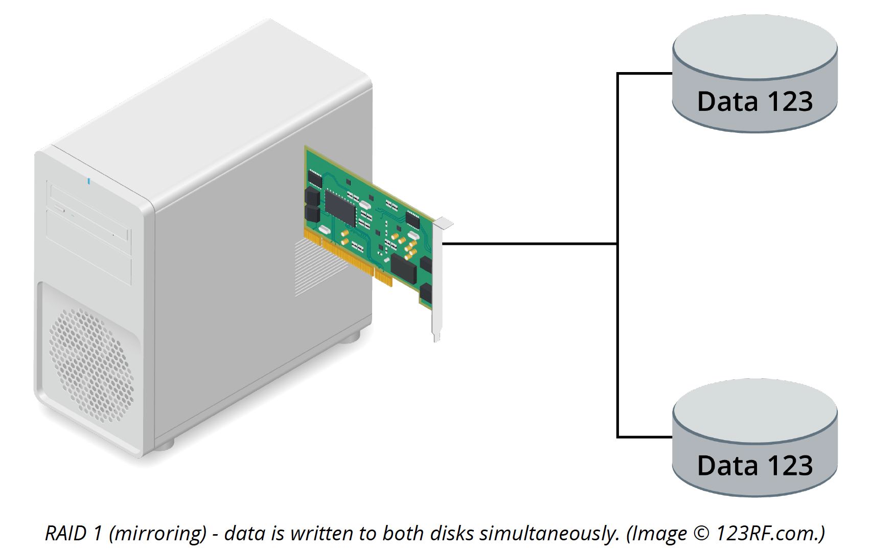
This strategy is the simplest way of protecting a single disk against failure--if one disk fails (degrading the array), the other takes over.
RAID 5
Striped disks is the process of dividing a body of data into blocks and spreading the data blocks across multiple storage devices. With RAID 5 Striped disks distribute information across all the disks in the array. The data and parity information is managed so that the 2 are always on different disks (see image below). If a single disk fails, enough information is spread across the remaining disks to allow the data to be completely reconstructed.
RAID 5 requires a minimum of 3 drives, but can also be configured with more.
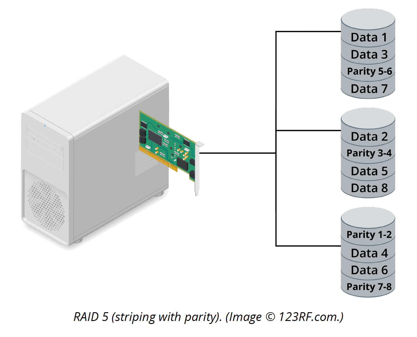
The level of fault tolerance and available disk space is inverse. As you add disks to the set, fault tolerance decreases but usable disk space increases. If you configure a RAID 5 set using 3 disks, one-third of each disk is set aside for parity.
RAID 10 1+0
Four or more drives are made into 2mirrors that are striped (see below).
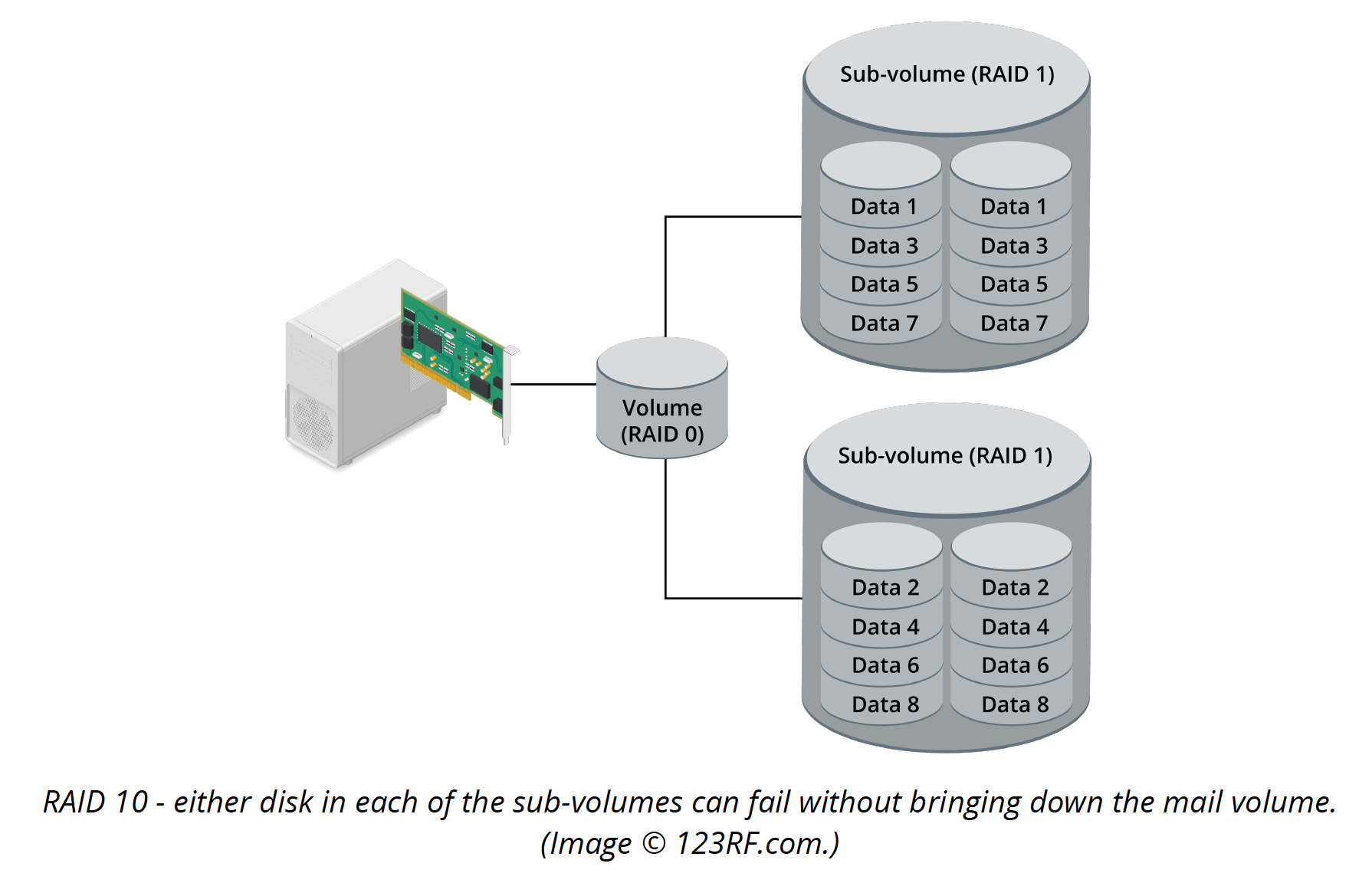
A logical striped volume is configured with 2 mirrored arrays. This configuration offers excellent fault tolerance as 1 disk in each mirror can fail and the array will still function. You will need at least 4 disks to create this configuration and there must be an even number of disks.
Common connectors
There are various types of connectors used when computer parts need to communicate with one another. The purpose and type of disk used will dictate the type of connector that is compatible.
Below are some examples of different types of connectors.
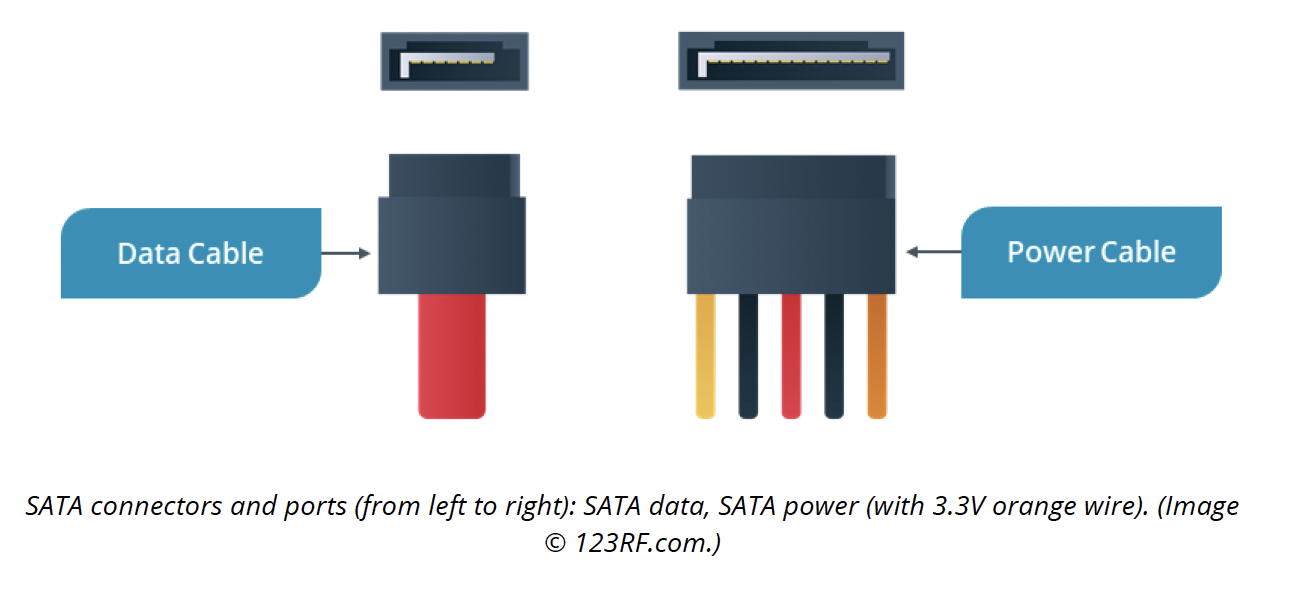
SATA
SATA transfers data in serial format, which allows for thin, flexible cables of up to 1 m (39"). The cables are terminated with compact 7-pin connectors. Each SATA host adapter port supports a single device.
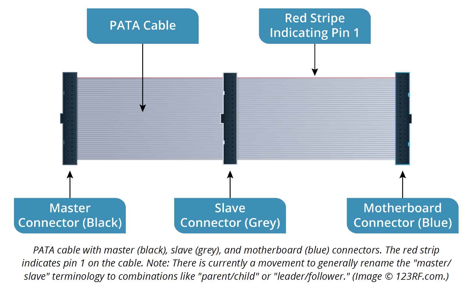
PATA/IDE
A PATA drive features a 40-pin port but typically uses 80-wire shielded cables, which are required for UDMA4 or better transfer modes. PATA cable is supposed to be up to 46 cm (18") long with each PATA cable typically having 3 connectors: 1 for the motherboard and 1 for each device.
The following image illustrates how most cables are 'Cable Select', allowing the master and slave device to be identified by the position of the connector on the cable. Pin 1 on the cable must be oriented with pin 1 on the connector. On the cable, pin 1 is identified with a red stripe. The connectors are also keyed to prevent them from being inserted the wrong way around.
SCSI
A Small Computer Systems Interface is a smart bus used when computer parts need to communicate with one another. There will be 2 connectors that form a connection to allow you to add devices (e.g. a computer and disk drive).
There are various versions of the SCSI connectors, below are a few options.


floppy
A floppy cable is a ribbon cable that is used to allow one or more floppy disks to connect to a computer.
The floppy drive connects to the computer motherboard. The image above is an example of a floppy channel connector.

Firewire
Firewire is a cable used to add peripherals to a computer. Due to its fast performance, it is also popularly used in connecting external hard drives and digital video for portable storage. This is due to its high transfer rate.
The adaptor cables come in 4-, 6- or 9-pin connectors (see image above).
4-pin connector
The 4-pin connector is used to connect peripherals as it holds no power. This is commonly used on laptops.
6-pin connector
The 6-pin connector provides DC power and is often used on desktop computers.
9-pin connector
This is commonly used on Apple computers.

USB
Universal Serial Bus (USB): A hardware interface standard designed to provide high-performance connections for numerous peripherals with minimal device configuration.
Connectors (see image above) and ports:
- Type A (4-pin) connects to hosts.
- Type B (4-pin) connects to devices. Includes B Mini and B Micro.
- Type C connects to hosts and devices.
Cable length:
- Low Speed and Super Speed: 3 m.
- Full Speed and High Speed: 5 m.
Hot swapping
'Hot swapping' is a component that can be inserted or removed whilst the computer is running, without interfering with the normal runnings of the computer.
A positive to hot swapping is that it can be used without causing any damage to your device.
Causes of hard disk damage
There are several reasons why hard disks may fail. These may include:
- human error
- firmware or manufacturer error
- overheating
- electronic failure or power surge
- mechanical or internal failure.
Human error
Unintentional damage to hard disks is one of the most common causes of failure. From dropping them on the floor through to accidental deletion of files or directories are some of the reasons that can cause hard disk failure. This may cause permanent data loss to users.
Although this type of failure can be hard to recover, one possible solution to rectify this type of failure would be to recover lost files using data recovery software.
Firmware failure
Firmware failure may include firmware or manufacturer faults. These typically create damage by providing improper voltage or faults within the disk drive itself. This can cause the hard disk to be unrecognisable which will cause the system to 'hang' or fail to boot.
Overheating
Overheating can occur due to a faulty CPU fan or improper ventilation and airflow obstruction. For example, leaving your computer on a soft surface for a long period will restrict airflow and reduce the ability of the computer to undergo cooling processes.
Electronic failure
Electronic failure in hard disks can be caused by unreliable power sources as well as an improper power supply by UPS. This can cause sudden start-up failure as well as BIOS not being able to identify the hard drive.
Mechanical failure
Mechanical failure can be caused through wear and tear by moving parts over time. It can also be caused by malware or virus attacks on the system. This will lead to a complete system freeze, lack of booting and corrupt files and folders.
To avoid mechanical failure, it is recommended to keep your system updated, including any anti-virus systems.
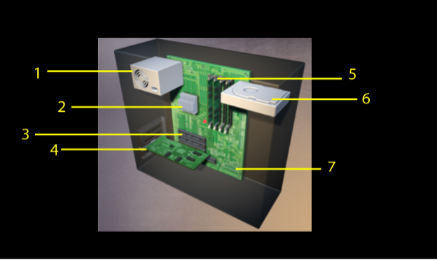
Identify the following components from the image below.

Electrical circuits
Electricity is the flow of electrons through a conductor. The characteristics of the electricity supply are measured as voltage, current (amperage), resistance and power.
- Voltage—the potential difference between 2 points (often likened to pressure in a water pipe) measured in Volts (V).
- Current—the actual flow of electrons, measured in Amps (I). A current flows in a circuit, which is made when conductors form a continuous path between the positive and negative terminals of a power source. The size of the current is determined by the conductivity of the circuit (e.g. a higher current can flow in a thicker wire than can in a thinner wire).
- Resistance—a degree of opposition to the current caused by characteristics of the conductor, measured in Ohms (Ω or R).
- Power—the rate at which electricity is drawn from the supply by the device using it, measured in Watts. Power is equal to the voltage multiplied by the Current (W=V*I).
- Energy—the amount of power consumed by a device over time. This is measured in Watt-hours (or more typically, Kilowatt-hours [kWh]).
In a Direct Current (DC) circuit, the charge flows in one direction from the positive to negative terminals of the power source at a constant voltage.
DC is used for electronic circuits, which require stable voltages.
Grid power is supplied as Alternating Current (AC), which means that the current flows in both directions around the circuit and the voltage alternates between low and high values.
Variations occur across locations; e.g. in the UK, grid power is supplied at 220-240 V; while in the US, grid power is 110-120 V. (This will be addressed in more detail soon!)
AC is a cheap way to distribute electrical power over long distances but is incompatible with PC electronics and so transformers in the PC's power supply are used to convert AC to DC voltages.
The generic electrical components used in a PC's electronic circuits are itemised below.
- Conductor—a material that is good at conducting electricity, such as gold, copper or tin. These are used for wires and contacts.
- Insulator—a material that does not conduct electricity, such as rubber or plastic. These are used as sheaths for wires to prevent short circuits or electric shocks.
- Semiconductor—a material that can act as both a conductor and an insulator. This provides switch-like functionality, where a circuit can be opened and closed, used to represent binary (on/off) digits.
- Resistors—these oppose the flow of current without blocking it completely and are used to manage electronic circuits.
- Diode—a valve, allowing current to flow in one direction only. These are used in a computer's power supply and as protection for components.
- Fuse—a safety device. The flow of electricity creates heat. A fuse is designed so that if the current is too high, the heat will cause the fuse wire to melt and break, breaking the circuit and shutting off the current.
- Transistors—in computers, these are semiconductor switches used to create logic devices. Typically, a type called a Field Effect Transistor (FET) is used to make components such as CPUs and memory.
- Capacitor—this stores electrical energy and is often used to regulate voltages. Note that a capacitor can hold a charge after the power is removed.
Function of a power supply unit
Power supply units (PSUs) are required in all computer systems since computers are designed to run on direct current (DC), but our home and office outlets only provide alternating current (AC).
For a computer to run well, it requires good, clean power from the outlet to the computer’s PSU. The PSU then converts the AC input into DC output to the various subsystems of the computer at the necessary voltages.
The PSU creates heat in this transformation from AC to DC. Therefore, a good power supply fan is essential to remove the heat from the PSU and computer system.
watCh - power specifications (9:44 minutes)
Let’s watch the following video on power specifications.
Power supplies are rated in Watts, with contemporary computer systems requiring 400 Watts of power or more. Every device inside the computer requires power and receives it from the PSU. Therefore, the more devices there are inside the computer, the more power that is required from the power supply.
Europe, US, AU and NZ power standards
A PSU must be able to supply adequate power to all the PC's components.
The maximum power output (power rating) available from a PC power supply is measured in Watts, calculated as voltage multiplied by current (V*I).
The PSU found in a standard desktop PC is typically rated at around 200-300 W. This is normally sufficient for a full range of expansion cards and peripherals.
- Slimline desktop PCs may be fitted with 100-200 W power supplies.
- Tower systems and servers often have units rated over 300 W; enough to power many more disk drives, tape units, and other storage devices than would be fitted in a desktop PC.
- Gaming PCs might require 500 W or better power supplies to cope with the high specification CPU and graphics card(s). (Adapted from CompTIA)
Most of today’s computers are built around the world with different voltages.
In the United States, power is delivered at 115–120 VAC (voltage alternating current) at 60 Hertz (Hz). In Europe and Asia, the typical wall outlet provides 230–240 VAC at 50 Hz.
If the power supply supports dual voltage, you need to ensure the correct setting is selected. In that situation, there should be a slider button that allows you to select the proper voltage. Slide the button to the appropriate voltage before plugging the power supply into the wall or damage to the computer can occur.

Replace or repair if damaged?
A power supply is a field replaceable unit (FRU) and should be replaced—never repaired—because the capacitors will hold voltage well after the PSU has been unplugged.
You should never disassemble a PSU. When it is broken, simply replace the entire unit. Power supply units are relatively inexpensive, so it is best practice to simply replace them.
Some technicians wonder why they should not disassemble or open the PSU and try to fix it, but the reason is simple—it is very dangerous!
A PSU has numerous electrical components that allow it to convert the high-voltage 115-120 VAC (or 230-240 VAC) power into the 12 VDC (volts direct current) that is usable by the computer. Some of these components are capacitors, which cause the power supply to retain lots of voltage (up to 10,000 Volts or more) even after the computer is turned off and even after the computer and PSU are unplugged.
What are the safety risks?
What do you think would happen if we selected the wrong voltage before plugging a unit in?
Well, if we are in Europe and expecting 230 VAC from the wall but incorrectly set the switch to 110 VAC (the United States standard), the power supply would receive an overvoltage condition, damaging the power supply and possibly starting a fire.
If instead we took a European PC, which expects 230 VAC, and plugged it into a United States electrical outlet providing 110 VAC, we would get an undervoltage condition, and the computer would not start.
What are the indicators of a safe and properly tested PSS?
A technician should verify that the backward 'UR' logo appears on the power supply since this indicates that the power supply has been properly safety tested.

Power supply safety standards, agencies and marks, Copyright CUI Inc.
Determine the power required for proper computer operation
When purchasing a new computer, the power supply will already have been selected based on the initial configuration of the machine, but if you are adding new components to the workstation, you will need to verify that the power supply has enough wattage to support the existing and new components.
To do this, you need to determine the wattage by adding all the devices’ wattage together. If the device is measured in Amps, multiply Amps by Voltage (A x V) to calculate the Watts.
Power supplies are not 100 per cent efficient, nor are they rated to be 100 per cent efficient. Therefore, you should always keep the total wattage under 70 per cent of the rated wattage of the power supply to ensure proper computer operations.
CompTIA guidelines in calculating the amount of power needed for a PC will help ensure that you have enough power available for all the devices on the PC. The process is fairly simple:
- List the devices that need to have power served by the PSU. Be sure to include the following:
- motherboard
- CPU
- RAM
- hard drives
- CD drives
- DVD drives
- floppy drives (if any)
- expansion cards.
- Determine the power requirements for each device.
- Add up the power requirements for the existing total power load.
- Consider adding a buffer of 20-30 per cent for future power needs.
- Examine the details on the PSU currently installed, paying particular attention to the maximum output.
- If you have not exceeded the power available, you do not need to upgrade the PSU.
- If you have, you will need to obtain a PSU with a higher output and install it.
PSS Connectors
ATX 12V 2.x power supplies connect to the motherboard by way of a 24-pin cable + 4-pin/8-pin for CPU and 6- or 8-pin for PCIe video.
The purpose of a 'dual-rail' PSU is to separate and limit the current through each wire to avoid overheating.
Originally, the ATX 1.x standard required 20 pins to provide the mainboard (motherboard) power connection. ATX version 2.x expanded this to 24 pins for a standard ATX12V power supply. Many power supplies will provide a 20+4-pin cable so that they are backward-compatible with older systems.
With the higher voltage requirements of the Pentium 4 and onward, the ATX version 2.x standard made this a 24-pin cable +4-pin (original mini-ATX or P4 connector) or an EPS12 8-pin connector. The ATX12V provides a 4-wire square connector for additional motherboard power. ESP12V provides an 8-wire connector (often split into two 4-wire connectors for backward-compatibility) for additional CPU power.
Finally, there is the AUX connector, a 6-wire connector to provide older systems with extra power to the motherboard.
| Power cable | Application | Pinouts/Voltage |
|---|---|---|
 |
IDE/EIDE PATA devices (HDD/ODD); Case Fans; PCI/PCIe Expansion cards requiring external power (i.e. USB, Firewire, Thunderbolt) | Red (+5V), Yellow (+12V), Black (G) |
 |
SATA Devices (HDD/ODD); PCI/PCIe Expansion cards requiring external power (i.e. USB, Firewire, Thunderbolt) |
15-pin (+3.3 V, +5V, +12V)
|
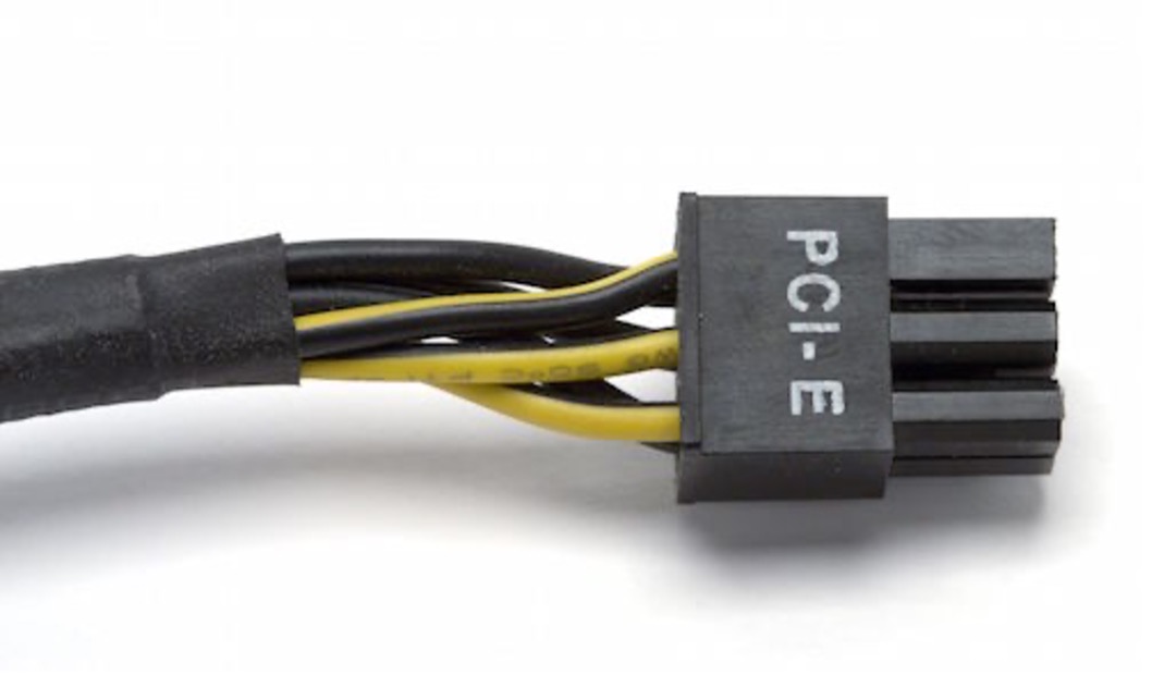 |
PCI Express Video Cards – 6 or 8 pins | 6-pin (+12 v) (ATX12V Vers. 2.1) 8-pin (+12 v) (ATX12V Vers. 2.2) or later |
ATX12V version 2. x eliminated the 3.3V and 5.5V rails in favour of 12V rails due to the nature of CPU and PCIe power requirements. The ATX standards from version 2.x on have all been developed to improve power delivery. The 12V dual-rail PSU is designed to limit overvoltage situations and protect against overheating.
As discussed earlier, in addition to the motherboard needing the power to function, peripherals need the power to function, too. The power supply provides additional connectors for peripherals used throughout the computer system.
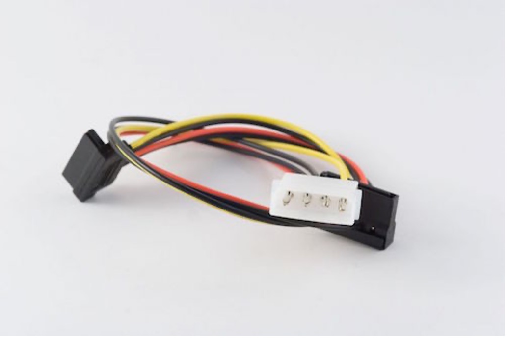
The oldest style connector is the Molex connector and is used for PATA hard drives, PATA CD/DVD drives, and extra cooling fans. The Molex is a 4-pin connector that is usually one of the largest connectors. A mini-Molex or Berg connector is a 4-pin connector that is rather small and only used for floppy disk drives, specifically the 3.5-inch variant of the drive.
SATA devices use SATA power cables, which are 15-pin L-shaped connectors.
PCIe power connectors (peripheral component interconnect express) are 6-pin or 8-pin connectors that are used to provide additional power to PCIe video cards at 12 VDC.
If you run out of connectors of a certain type, there are conversion cables to make a Molex into SATA, or Molex into PCIe. Further, there exist Y-connectors for Molex that allow a single Molex to be split into 2 Molex connectors. As you remember, power supplies convert AC to DC power to provide power to the devices. These connectors have either +/-3.3 VDC, +/- 5 VDC, or +/- 12 VDC.
watch - computer power connectors (5:15 minutes)
Watch the following video about the different power supply connectors available.
Powering Mobile Devices
Until recently, each mobile device you purchased would have a power adapter supplied with it. Laptops would have a specific barrel connector and smartphones would have some form of micro-USB connector. These adapters convert the AC current supplied from the grid to the DC voltage used by the devices. As the DC voltage varied from device to device the barrel connectors differed in size and polarity.
Since these were mobile devices, the AC adapter was normally “universal”, meaning it would handle inputs from 11-240V and 50 or 60Hz. Some adapters had interchangeable pins so that can be used in different regions of the world.
When buying a new mobile device, such as a phone, you may find it does not come with a power adapter at all. That is because these devices can be charged via the ubiquitous USB-C connection The USB-C connector allows the device and the adapter to negotiate the power supplied, meaning one connector can be used for multiple devices.
As these devices are portable, they require an internal power source to allow them to run when not connected to an external power source. This is provided by the battery.
Almost all mobile devices use rechargeable Lithium ion (Li-ion) batteries. While Li-ion batteries are superior to the earlier Nickle Cadmium (NiCad or Ni-Cd) there are safety concerns that have led to airlines restricting the carriage of Li-ion batteries over a certain capacity.
Mobile devices have a battery driver to prevent damage to the battery by implementing things such as “trickle charging” (charging at a low rate just above what is being used by the device), stopping the battery from being fully discharged, and preventing over-charging of the battery.
The following article describes the different types of Li-ion batteries you may encounter: The Six Major Types of Lithium-ion Batteries.
Maximising Battery Life
All rechargeable batteries have a limited lifespan. Eventually, they will no longer be able to store a charge. Maximising the life of a Li-ion battery reduces replacement costs and helps minimise the environmental impact of disposal. The following recommendations have been developed to extend the life of Li-ion batteries:
- Minimise exposure to extremely high or low heat, both when using and storing the battery. This extends to the storage of electric vehicles.
- Minimise the amount of time the battery spends with 100% or 0% charge. Unplug devices when they reach 100% - don’t leave them plugged in all the time.
- Avoid using fast chargers as they can degrade the battery.
- Avoid discharging batteries too quickly. Batteries are quickly discharged when multiple apps are open or when HD videos and 3D games are used.
- Do not store batteries in their charger.
- Avoid puncturing the battery.
- Avoid using or storing batteries in high moisture environments.
- Follow all manufacturers’ instructions.
Many motherboards support expansion through Peripheral Component Interconnect (PCI) or PCI express (PCIe) slots.
PCI is an older standard that uses a parallel bus structure and, while still included on many modern motherboards, it is primarily to support legacy hardware.
PCIe is a new standard that uses a serial bus structure and supports much faster communication.
Expansion slots can be used to add:
- additional network interfaces
- RAID storage controllers
- sound cards
- graphics cards.
PCI express
PCIe slots come in 1x, 4x, 8x and 16x with a corresponding slot length and bus width.
Expansion cards that use a smaller slot can be inserted into a bigger slot leaving the rest of that slot unused.

The 16x PCIe slot is commonly used for discrete graphic cards, which allows a system to render 3D graphics and encode or decode video faster and more efficiently.
Graphics processing unit
Nearly all desktop and laptop systems need to present information on a screen.
Some systems have relatively low graphic requirements, with a basic operating system and browser interactions being their main use. Other systems may have very high graphic requirements for rendering the 3D graphics and lighting for games and video production.
'Integrated' and 'discrete' graphics are the 2 main ways a computer system can access graphics hardware.
Integrated graphics
Most CPUs come with integrated graphics. As the name suggests, it is part of the CPU that has special graphics capability and function. It shares the system memory.
Accessing integrated graphics is done by plugging a monitor into a display connector on the motherboard.

Discrete graphics
Using a GPU that is separate from the CPU is known as discrete graphics. A graphics card is installed into an empty 16x PCIe slot on the motherboard and monitors are connected directly to it.
A discrete GPU has its own process and RAM. The RAM that a graphics card uses is known as VRAM (video RAM) and is much faster than standard RAM.
There are currently 2 main competitors in the graphics card technology market: Nvidia and AMD. Each of these brands can be bought from other brands who are using their technology.
In some cases, the graphics card can be the most expensive component of a computer system.
As mentioned in the section on hardware components, IT systems have a range of purposes, but require similar functionality (input, processing, storage, and output). The components are often customised based on purpose. A laptop is designed for transportability. A desktop is based around airflow to enable more processing power. A VoIP phone is packaged in a way to enhance functionality and demonstrate purpose. A CCTV camera for discretion. A router is an IT device designed for connecting devices to other networks.
In the next subtopic we will review major hardware forms and how the functionality has influenced the way that the components are put together.
While the outside of a computer (or PC) might vary from vendor to vendor, the inside usually conforms to some common standards.
Inside most PC cases, you will find:

Power supply
When sized appropriately, the power supply delivers the required voltages to the different components of the computer.
Motherboard
The motherboard is the central component of the computer. The CPU (processor), memory and storage (hard drives) are directly connected to the motherboard.

- PCI
- north bridge
- processor socket
- south bridge
- memory
- IDE
Hard drive
SSD (solid-state disks) and mechanical hard drives are usually connected to the SATA port on the motherboard. SATA ports are connectors that connect the hard drive to the motherboard. Many PCs however now use M.2 SSDs connected to PCIe on the motherboard for greater bandwidth and data transfer rates.
Depending on the system, you may also find additional expansion cards including graphics and network cards, and an optical drive (either DVD or Blu-ray).

- motherboard
- optical drive bays
- power source
- hard drives
watch -tour of the parts inside a computer (12:34 minutes)
Watch the video below to tour the inside of a computer.
While desktop configurations are relatively standard, internal laptop configurations can be a little more complicated.
The same components that make up a desktop computer will often be part of a laptop, they are just a little harder to access.
A laptop's motherboard remains central to the system and is also responsible for power distribution.
The CPU and graphics chips are generally soldered to the motherboard. There is often a removable panel to access RAM and storage for upgrading; although some manufacturers (e.g. Apple) solder the RAM and storage to the motherboard, making it impossible to upgrade or replace.
Watch - How a laptop works and its components (11:47 minutes)
Watch the video below to learn how a laptop works and more about its components. Once you have watched the video, share aspects you found interesting in the forum.
Mobile Devices

A 'mobile device' can be defined as any device that can send and receive signals through the transmission of voice, video and sound.
Examples of mobile devices include:
- laptop
- tablet
- mobile phone
- smartwatch.
Mobile Hardware
The hardware components within the mobile device support:
- processors
- graphics
- memory and storage
- display/touch screen
- batteries.
See the major components within a mobile device in the following illustrations.


- front camera
- on/off switch
- back camera
- flash
- ringer on/off
- volume up
- volume down
- SIM card slot
- lightning connector port
Processors
A 'mobile processor' is a CPU chip that is also used for laptops and other portable devices. They run on lower voltages and are designed to run cooler than the CPU chips used in laptops and desktops.
The processor within your mobile ensures all processors are running smoothly. This can include opening apps, browsing the internet, playing games and listening to music. These actions are then converted into visual displays on your mobiles interface.
Graphics
The mobile GPU (Graphics Processing Unit) is a co-processor designed to accelerate graphics applications, user interfaces and 3D content on your mobile device.
Memory and storage
Every mobile needs to have an adequate amount of space and memory--this is where RAM (Random Access Memory) is used. This is part of the mobile device that is stored in the operating system where data is kept. It is an important hardware piece as mobile devices use memory and storage to hold photos, videos, games and apps.
Display/touch screen
A display/touch screen is how the user will use to give commands to, and navigate through, the mobile device. With a touch, the user can swipe left, right and click on the various apps needed--typing and sending messages as well as making phone calls. Without the touch screen, the user would not be able to operate the mobile device.
Batteries
Every smartphone requires a battery to keep it running. This is installed within the mobile device. Users need to continually recharge their mobile devices as without a charged battery, the phone will be unable to turn on.
Batteries are made with 2 ingredients: lithium-ion batteries and graphite. Energy is released when lithium ions move from the graphite layer to the lithium cobalt oxide layer.
Check your understanding.
Personal Devices in an IT environment
Even though there have been "smart personal devices" since 1994 (called the IBM Simon) the first iPhone in 2007 revolutionised personal devices. (Smith, 2018) These devices have taken on an important role within IT. They are compact, portable gadgets that have become integral to our daily lives. These devices serve various purposes, from communication to entertainment. Smart phones and tablets have become so powerful that they can perform many functions of devices like laptops.
Personal devices include things like:
- Smartphones
- Tablets
- Wearable devices
- E-readers
- E-writers
Why Are Personal Devices Important?
Once of the major factors around the growth of personal devices is convenience. They are connected via the mobile phone network or a Bluetooth connection which provides connectivity and more frequent updating of information.
The improved connectivity brings productivity benefits. Enhanced communication leads to more productivity through information being received sooner and without the need to visit the office. An order can be put into the system as it is taken in a client's office or a document can be worked on by different people in different places at the same time.
Not only do personal devices allow better communication with colleagues and clients it also provides better access to resources. Up till about 2010 Microsoft used to publish CDs with technical documents on them that engineers would take with them to look up specifications when they came across unfamiliar technologies (which was very frequently). These were called "TechNet". These were updated about every 6 months with significant costs and delays in getting information out about new technologies. These were replaced by online documents (https://technet.microsoft.com). This has become Microsoft Learn and is updated as the new documents become available making it available to Engineers as they need it to learn or research problems while on site. All via their phone.
While not strictly productivity they have also enhanced the work environment. Many workplaces allow employees to use headphones to listen to music while working because this allows them to focus on the task at hand.
What Are the Security Concerns?
There are significant security concerns with personal devices. Personal devices tend not to be as secure as devices owned by organisations, and those seeking to create a backdoor that they can sell to other malware players will target devices such as routers and BYOD (Bring Your Own Device) with phishing attacks.
Once a personal device has been compromised there are many avenues of attack open for intruders. They can use the device to infect other devices, to use the camera to capture information, to get wireless access details, and many other actions.
The fact that there is a mixture of personal and work information on a personal device also puts the corporate data at risk when a device is lost or stolen. A few years ago in New Zealand there was an infamous situation where a Security Intelligence Service (SIS) lost a briefcase and there was significant concern about leaked sensitive information. There have been other similar incidents, but at the end of the day it came out that the only thing in the briefcase was his lunch (a pie) but it demonstrates how easy it is for information to be lost when a phone is misplaced.
These are some of the security risks so while personal devices enhance our lives but come with security trade-offs. Organisations and individuals must strike a balance between convenience and safeguarding sensitive information.
Activity
Consider the following questions:
- What type of computer are you using?
- What are the brands and model numbers of the peripherals you are using?
- Why did you choose to use your hardware?
Nearly all interactions an end-user will have with a computer will be using a peripheral device. A 'peripheral device' is an external or internal device that connects directly to a computer or other digital device, but does not contribute to the computer’s primary function--computing.
Input devices
Human Interface Devices (HIDs) are peripherals connected to a computer that enable users to enter data and give instructions. Keyboards and pointing devices are the most common types of input devices on modern computer platforms. However, a huge range of input devices include game controllers, drawing interfaces, and hand or eye trackers.
Keyboards
Keyboards have been around the longest. Many early computers were only interacted with using a keyboard and a command-line interface.
Most users will be familiar with a standard QWERTY layout that includes a row of function keys and often a number pad on the right-hand side (see below).

- function keys
- numeric keypad
- caps lock
- command
- arrow/navigation keys
A keyboard is used to enter text and execute shortcuts. Most current operating systems and applications share very similar shortcuts.
For example, CTRL+P on a Windows computer is most often used to print a document or page. Command+P in MacOS is the same.
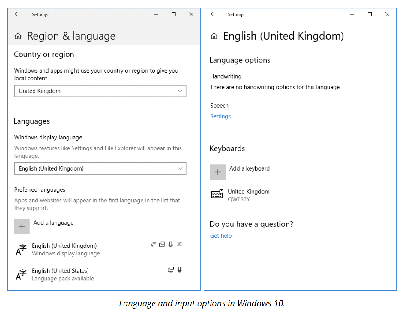
A keyboard's layout and language are often automatically detected by an operating system, and these options can be changed in the Region & Language system settings.
Modern keyboards are connected to a computer with either a USB cable or wirelessly, often using Bluetooth.
Pointing Devices
While it is possible to navigate most modern operating systems using only a keyboard, they are usually designed to be used with a pointing device, often a mouse.
Mouses
Apple is widely credited with popularising the mouse when they introduced a version of the technology on the original Macintosh in 1984.
Early mouses used a rotating ball with encoder wheels to translate movement to a pointer on the screen.
Modern implementations of the mouse use optical or laser technology, enabling improved tracking and reliability.
Mouses are connected using USB or wirelessly, also often using Bluetooth.

Touchpads
Touchpads are the most ubiquitous pointing device found on modern laptops. They are touch-sensitive surfaces that can translate the movement of a user's finger on the surface into the movement of the on-screen pointer.
Over the years, touchpads have become larger on many laptops and are also available as a desktop peripheral.

Displays
There are many types of display technologies that can be connected to a computer, including projectors and VR headsets; although the primary way users will see what they are doing on a computer is by using a monitor.
Cathode ray tube (CRT) monitors were the standard for computer monitors for decades, until the early- to mid-2000s when LCD flat panel displays began to outsell the CRT.
Now, LCD, LED and OLED displays are commonplace at home and in the office for both desktop and laptop computers.
The acronym TFT is often associated with LCD displays. TFT stands for Thin Film Transister and refers to the technology used to control the colour each pixel displays.
There are two common types of TFT:
- Twisted Nematic (TN)
This type of display is known for its low latency and response time and high refresh rate, making them less prone to motion blur. Users interested in competitive gaming often value high refresh rates.
TN panels tend to have a narrower viewing angle and lower colour accuracy, making them less appealing to use in graphic design and video production environments. - In-Plane Switching (IPS)
This type of panel is known for its greater colour accuracy and wide viewing angles, traits often valued by users working in graphic design or video production.
IPS panels are often capable of reproducing a wider colour gamut making it possible to reproduce a greater range of colours.
OLED
Another display technology that is becoming more prevalent is OLED (organic LED). A major advantage of this type of display is that each pixel produces its own light, removing the requirement of a backlight. With no backlight, these displays can be much thinner, and reproduce much deeper blacks.
Modern display resolutions will usually conform to a variant of the XGA standard or more likely HD. Some of the most popular resolutions are listed below.
| Standard | Resolution | Aspect Ratio |
|---|---|---|
| WXGA (wide screen XGA) | 1280x800 | Widescreen (16:10) |
| SXGA (Super XGA) | 1280x1024 | 5:4 |
| HD | 1366x768 | Widescreen (16:9) |
| WSXGA | 1440x900 | Widescreen (16:10) |
| HD+ | 1600x900 | Widescreen (16:9) |
| Full HD | 1920x1080 | Widescreen (16:9) |
| QHD (Quad HD) | 2560x1440 | Widescreen (16:9) |
| 4K UHD (Ultra HD) | 3840x2160 | Widescreen (16:9) |
Display Connectors
If you have been around computers for a while then you will probably be familiar with the (now obsolete) 15-pin, blue VGA connector.

VGA
VGA was an analog interface used on CRT and early LCD monitors and was capable of up 1600x1200 resolution.

DVI
Digital Video Interface (DVI) was the successor to VGA. It became the new standard when it was introduced in 1999.
DVI is capable of both digital and analog signals, meaning it could support older CRT monitors. This does depend on which type of DVI was supported by the output and the cable:
- DVI-I supports both analog equipment (such as CRTs) and digital
- DVI-A supports only analog equipment
- DVI-D supports only digital.
DVI bandwidth in single-link mode is 3.7 Gbps, enough for full HD resolution (1920x1200) at a frame rate of 60 fps. More bandwidth can be obtained through connectors that support dual-link mode. Dual-link supports over 7.4 Gbps, enough for HDTV @ 85 fps. A single-link connector can be plugged into a dual-link port, but not vice versa.
There are economy and premium brands of DVI cable. Cables have to support an HD signal at a length of at least 5 m (16.5 ft). Better quality cables (using thicker wiring and better shielding) will support longer lengths.

HDMI
The High Definition Multimedia Interface (HDMI) is now the most widely used cable standard amongst all display and graphic interfaces. It is found on nearly every consumer product used for displaying video (i.e. television, DVD players, Blu-ray players, game consoles etc.).
The HDMI signal can support both digital video and audio, while also providing remote control, allowing devices to communicate with each other.
There is a range of standards for HDMI, with each supporting different HD resolutions, data rates and cable lengths.

DisplayPort
While HDMI is a standard developed by a collective of consumer electronics companies (requiring a licence to implement), DisplayPort is royalty-free, having been developed by the Video Electronics Standards Association (VESA).
DisplayPort compliments HDMI as it offers similar features and is also capable of supporting multiple daisy-chained monitors on the same cable.

Printers
Printers are often an important tool in many homes or office environments and can use various technologies to produce their output and communicate with a computer system.
Laser printer
Laser printers are popular in office environments because of their speed and capacity for high volume output and ability to duplex (print of both sides of the paper).
As illustrated in the diagram below, an electrically charged drum transfers toner (a very fine powder made from granulated plastic) onto sheets of paper to create the printed images.
A laser is used to indicate where on the drum toner should be applied before transferring to the paper.
The paper and toner are then guided through a fusing unit that applies heat, setting the toner to the paper meaning the images will not smudge or fade.

- laser
- projector
- toner
- corona wire charging the drum
- EP drum
- fusing unit using heat and pressure to adhere toner to paper
- paper source
InkJet printer
Inkjet printers use ink instead of toner (see the diagram below). This ink is a liquid and is usually in the colours cyan, magenta, yellow and black; although some specialised photographic printers include additional colours such as grey, light cyan and light magenta, enabling them to reproduce a wider colour gamut.
Inkjet printers are more common in the home or home office, as their output is usually slower and volume more limited.

- ink sprayed onto paper
- print head and reservoir
- paper
- rollers
Other types of printers
There are many other types of printers including thermal, 3D and impact. Each will have a unique way of creating its output; however, the process for installing almost any printer will have a lot of similarities.

Printer Installation
Local printer connections
USB is the most common connection used for locally connected printers. With the printer powered on and connected to the computer with an appropriate USB cable, the operating system will usually detect the printer and install a compatible driver.
You can confirm that a connected printer is functioning correctly by printing a test page from the Print > Settings window (see example below).
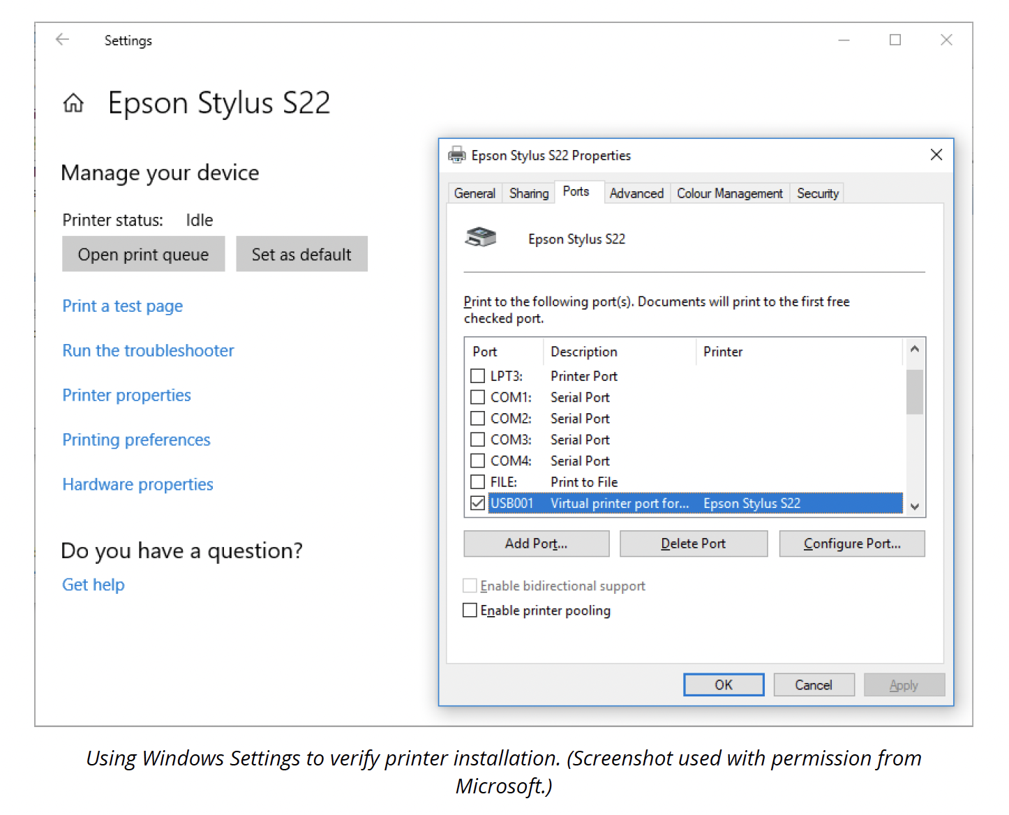
If the printer has specific functionality that is not available using the automatically installed driver, you may need to install the manufacturer's driver software that came with the printer or search the printer-specific driver online.
Network printers
Many consumer-level printers now feature wi-fi, and it is not uncommon for higher-level printers to include an ethernet port, making it possible to connect these printers directly to a network.
A network-connected printer will have its own IP address and can be connected using this, or it may broadcast its availability to the computer on the network for easier connection.
In some cases, multiple printers may be connected to a single print-server responsible for managing print queues and printing.
Safety Procedures
In order to complete PC support tasks without damaging the equipment you are servicing or causing physical injury, there are several tools to use and operational procedures to follow to get the job done quickly, safely and correctly.
Local government regulations
When performing PC maintenance work, you may need to take account of compliance with government regulations.
Regulations that typically affect PC maintenance or the installation of new equipment are:
- Health and safety laws: Keeping the workplace free from hazards.
- Building codes: Ensuring that fire prevention and electrical systems are intact and safe.
- Environmental regulations: Disposing of waste correctly.
For example:
New Zealand's WorkSafe (Mahi Haumaru Aotearoa) provides laws and when installing computers and working with electrical components, you must follow the Electrical codes of practice standards.
While specific regulations may vary from country to country and state to state, employers are generally responsible for providing a safe and healthy working environment for their employees.
Employees have a responsibility to:
- use equipment in the workplace in accordance with the guidelines given to them
- report any hazards.
Employees should not:
- interfere with any safety systems, including signs, warnings or devices (such as firefighting equipment)
- introduce or install devices, equipment or materials to the workplace without authorisation or assessing the installation.
Safety procedures
A company's health and safety procedures should be set out in a handbook--possibly part of an employee's induction handbook.
Health and safety procedures should:
- identify what to do in the event of a fire or other emergency
- identify responsible persons (e.g. for overall health and safety, nominated first aiders, fire marshals and so on)
- identify hazardous areas in the workspace and precautions to take when entering them
- describe best practices for the use and care of the workspace and equipment within it
- establish an incident reporting procedure for detecting and eliminating workplace hazards and accidents.
General emergency procedures
Below is an example of a general procedure for emergencies.
- Raise the alarm and contact the emergency services, giving them a description of the emergency and your location.
- If possible, make the scene safe (e.g. if you are faced with a fire, establish that you have an escape route, or if faced with electrical shock, disconnect the power--if it is safe for you to do so).
- If you have the training and it is safe to do so, do what you can to tackle the emergency (e.g. give first aid or use firefighting equipment).
Of course, circumstances might dictate that you do something differently.
It is vital that you keep calm and do not act rashly.
Electrical hazards
The most prevalent physical hazards that computer technicians face are electrical hazards. Electricity is necessary to run a computer, but it can also damage sensitive computer equipment and, in some cases, pose a danger to humans.
Following established best practices for promoting electrical safety will protect the computer equipment you work on, your safety and the safety of others.
Electrical equipment can give an electric shock if it is broken, faulty or installed incorrectly. It is important to test electrical devices regularly. The frequency will depend on the environment in which the device is used. In some countries, Portable Appliance Testing (PAT) carried out by a qualified electrician or technician ensures that a device is safe to use.
Electrical currents can pass through metal and most liquids, so neither should be allowed to contact any electrical device installations. Damaged components or cables are also at risk and should be replaced or isolated immediately.
The human body is an electrical conductor and a resistor, so a current will pass through it and make it heat up, manifesting as a burn if the current is strong enough. A current can interfere with the body's nervous system, which also uses electrical signals.
This might manifest as spasms or paralysis or, in a severe case, cause a heart attack.
Collateral injuries occur when involuntary muscle contractions caused by the shock cause the body to fall or come in contact with sharp edges or electrically live parts.
Electricity can hurt you even if you are careful and avoid becoming part of an electrical ground circuit. The heat generated by an electric arc or electrical equipment can burn your skin or set your clothes on fire.
Note: High voltages (over about 30V) are more dangerous because they have the power to push more current through you (skin's resistance drops at higher voltages), but it is the current that causes the actual damage. This is why static electricity is not dangerous to you, despite the high voltages. More current will flow if a larger area of your body is exposed.
Fuses
An electrical device must be fitted with a fuse appropriate to its power output. A fuse 'blows' if there is a problem with the electrical supply, breaking the circuit to the power source.
Fuses come in different ratings, such as 3A, 5A, and 13A. A device's instructions will indicate the fuse rating to use, but most computer equipment is rated at 3A or 5A. If the fuse fitted is rated too low, it will blow too easily; if the rating is too high, it may not blow when it should (it will allow too much current to pass through the device).
If multiple devices need to be attached to a single power point, a power strip of sockets should be used. If too many devices are attached to a single point, there is a risk they will overheat and cause a fire. 'Daisy-chaining' one power strip to another is dangerous. The total amperage of devices connected to the strip must not exceed the strip's maximum load (typically 12 Amps).
Electrical grounding
Electrical equipment must also be grounded (or earthed). If a fault causes metal parts in the equipment to become 'live', a ground provides a path of least resistance for the electrical current to flow away harmlessly. Most computer products (PCs, printers and so on) are connected to the building ground via the power plug.
However, the large metal equipment racks often used to house servers and network equipment must also be grounded. Do not disconnect the ground wire. If it has to be removed, make sure a competent electrician replaces it.

High voltage device safety
Most of the internal circuitry in a computer is low voltage (12 V or less) and low current, so there is not much of a threat to your safety. However, there are exceptions to this, which can be very dangerous. Power supplies, CRT monitors, the inverter card in an LCD's fluorescent backlight and laser printers can carry dangerously high levels of voltage.
Charges held in capacitors can persist for hours after turning off the power supply. You should not open these units unless you have been specifically trained to do so. Adhere to all printed warnings and never remove or break open any safety devices that carry such a warning.
Electrical safety
Follow these guidelines to work safely with electrical systems:
- do not work on electrical systems unless you understand the risks and appropriate safety procedures
- do not attempt repair work when you are tired--you may make careless mistakes and your primary diagnostic tool, deductive reasoning, will not be operating at full capacity
- do not assume anything without checking it out for yourself (e.g. a ground wire might have been disconnected or never properly installed)
- disconnect the power to a circuit if you must handle it
- hold down the power button on the device to ensure the circuits are drained of residual power
- test live parts with a multimeter to ensure no voltage is present
- always use properly insulated tools and never grip a tool by its metal parts
- take care not to touch any part of a circuit with both hands to reduce the risk of a serious shock--this is called the 'hand in pocket' rule (it reduces the chance that the current will pass through your chest and cause a heart attack)
- make sure your hands and the surrounding area are dry--sweat can make your hands more conductive
- do not leave any spill hazards in the vicinity and ensure you are not standing on a wet floor
- do not wear jewellery, a wristwatch, or other items such as name badges that may dangle from your neck or wrist, as they can cause a short circuit or become trapped by moving parts.
Toxic waste handling
Computer equipment conditions can be an issue when many airborne particles are flowing in and around various devices.
Contaminants can be gaseous--such as ozone, particles, dust or organics, from industrial processing of fossil fuels or plastics. There is also a risk of poisonous or corrosive chemicals leaking from faulty equipment.
Special care must be taken in respect of the following device types.
CRT monitors
A cathode ray tube (CRT) is an older computer monitor. These are very heavy and bulky and contain substantial amounts of hazardous materials; notably, lead. They also contain a glass vacuum tube and high-voltage capacitors. While the tube is designed to be shatter-resistant, it is still potentially very hazardous if dropped. The capacitors represent a high risk of electric shock.
Batteries
Swollen or leaking batteries from laptops or cell phones and tablets must be handled very carefully and stored within appropriate containers. Use gloves and safety goggles to minimise any risk of burns from corrosive material.
Electronic devices (PCs, cell phones and tablets)
Many electronic devices contain toxins and heavy metals (such as lead, mercury, and arsenic).
These toxins may be present in batteries, circuit boards and plastics used in the case and are not only harmful to human health if ingested, but they also damage the environment. This means that you must not dispose of electronic devices as general waste in landfills or incinerators. If an electronic device cannot be donated for reuse, it must be disposed of through approved waste management and recycling facility.
Toner kits and cartridges
Photocopier and laser printer toner is an extremely fine powder. The products in toner powder are not classed as hazardous to health, but any dust in substantial concentration is a nuisance as it may cause respiratory tract irritation.
ESD
Static electricity is a high voltage (potential difference) stored in an insulated body. Electrostatic discharge (ESD) occurs when a path allows electrons to rush from a statically charged body to another with an unequal charge. The electricity is released with a spark. The charge follows the path of least resistance so that it can occur between an electrical ground (such as a doorknob or a computer chassis) and a charged body (such as a human hand).
Although the voltage is high, the amount of ESD current sustained is very low, so static electricity is not that harmful. It can, however, be slightly painful. You might have felt a small shock when reaching for a metal door handle, for instance.
- You can feel a discharge of over about 2500V.
- A discharge of 20,000V or more could produce a visible spark.
Walking over an untreated carpet in dry conditions could create a charge of around 35,000V.
The human body is mostly water and does not generate or store static electricity very well. Unfortunately, our clothes are often made of synthetic materials (such as nylon and polyester) which act as good static electricity generators and provide insulating layers that allow charges to accumulate.
Humidity and climate also affect the likelihood of ESD. The risk increases during dry, cool conditions when humidity is low.
In humid conditions, such as before or during a storm, the residual charge can bleed into the environment before it can increase sufficiently to be harmful to electrical components.
An electronic component, such as a memory or logic chip, is composed of fine, conductive metal oxides deposited on a small piece of silicon. Its dimensions are measured in fractions of a micron (one-millionth of a metre). Any static electricity discharged into this structure will flash over (spark) between the conductive tracks, damaging or vaporising them. A transistor designed to work with 1-3V can be damaged by a charge of under 100V, though most ESD protection circuits improve this tolerance.
A static discharge may make a chip completely unusable. If not, it is likely to fail at some later time. Damage occurring in this way can be hidden for many months and might only manifest in occasional failures.
Component handling
By eliminating unnecessary activities that create static charges and removing unnecessary materials known as charge generators, you can protect against ESD-related damage and injuries.
There are several other prevention techniques that you can use to protect yourself and equipment when you are working with computer components.
- Self-grounding, or manual dissipation of static build-up by touching a grounded object before touching any electronic equipment. You can accomplish this by touching an unpainted part of a metal computer chassis or another component.
- Using an anti-ESD wrist strap or leg strap can dissipate static charges more effectively than self-grounding. The band should fit snugly around your wrist or ankle to maximise contact with the skin. Do not wear it over the clothing--the strap ground is made using a grounding plug that plugs into a wall socket or a crocodile clip that attaches to a grounded point or an unpainted part of the computer's metal chassis.
- An anti-ESD service mat is also useful. Sensitive components can be placed on the mat safely. The mats contain a snap connected to the wrist or leg strap. If the technician's clothing can produce static charges, an ESD smock, which covers from the waist up, can be helpful.
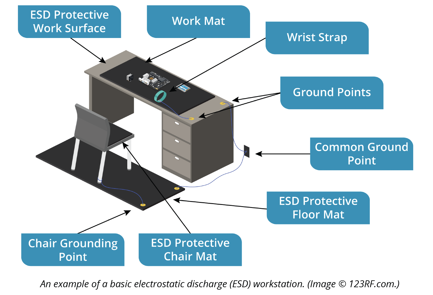
Electronic components, assemblies and spare parts (known as field replaceable units (FRUs)) are often shipped in anti-static bags to protect them from ESD damage.
Anti-static bag types
Anti-static packaging includes either anti-ESD shielding or dissipative material.
- Anti-ESD Shielding: this packaging reduces the risk of ESD because it is coated with a conductive material (such as a nickel compound). This material prevents static electricity from discharging through the inside of the bag. These bags are usually a shiny grey metallic colour. To protect the contents of the bag fully, you should seal it, or at least fold the top over and seal that down.
- Dissipative Packaging: this light pink or blue packaging reduces the build-up of static in the general vicinity of the contents by being slightly more conductive than normal. A plastic bag or foam packaging may be sprayed with an anti-static coating or have anti-static materials added to the plastic compound. This is used for packaging non-static-sensitive components packed in proximity to static-sensitive components.
Answer the following question:
What should Alex use?