
When you are undertaking a levelling task, there are processes that need to be considered. While the levelling tasks may vary, there is a general process that you can follow to ensure you are carrying out the levelling with precision and accuracy. The following steps breakdown the basic levelling process.
Step 1: Planning and preparation
- Reviewing plans and specs
- Checking legislation, Standards, WHS and environmental requirements, workplace requirements
- Selecting tools and equipment
- Selecting PPE
- Inspecting the worksite
- Confirming team roles.
Step 2: Conducting the levelling activity
- Identifying the required heights or levels
- Setting up the device
- Checking tolerances
- Shooting levels and transferring levels
- Documenting results.
Step 3: Cleaning up
- Cleaning up the site
- Checking, maintaining, and storing tools and equipment.
The levelling team
In most cases, you will require at least on other person to assist you with levelling activities. Take some time at the start of the day to decide on your roles and to clarify the plan for communicating with each other. Especially if you are working on a noisy site that requires hearing protection or if you will be working across extended distances.
In some cases, people use standard hand signals to communicate with each other where verbal communication is not possible. While the hand signals themselves may vary, the important thing is that you both share a common understanding of the signals that you will be using.
Safety considerations
Levelling requires a high level of concentration and you are often highly focussed on one specific point. It can be easy to lose track of what is going on around you and to suffer from lapses in situational awareness. Be particularly vigilant when you are moving around the site. Watch for vehicles, pay attention to barricades and signs, and remind yourself regularly of the hazards on site.
Plans and specs
Pay particular attention to the plans and specifications for the task that you will be working on. Levelling is precise and, as you saw earlier, the quality of the work that you do can impact the quality of the rest of the build. It is important that you are accurate to the plans and specs as well as to the work that you do on site.
Plan interpretations
When looking at the plans and specifications, you will find the plans may appear very overwhelming with the images and symbols. The following tables act as a key to help you when it comes to interpreting this complex documents. As you learn them, you will come to find some of the abbreviations are quite self-explanatory. To make it easier to understand, the tables have been divided into the following categories:
- House plan abbreviations
- Plan view annotations
- General plan view and fittings
Please be aware, these are some of many of the abbreviations you will see when you are interpreting plans. At the end of this module, be sure to refer to your additional resources to learn the extended variations of these abbreviations, annotations, and symbols.
House plan abbreviations
The following table outlines some abbreviations commonly identified on house plans.
|
Abbreviation |
Interpretation/ meaning |
|
AL |
Aluminium |
|
AP |
Acoustic plaster |
|
ASPH |
Asphalt |
|
B |
Basin |
|
BWK |
Brickwork |
|
C |
Cooker |
|
CAB |
Cabinet |
|
CF |
Concrete floor |
|
CR |
Cement render |
|
D |
Door |
|
DP |
Downpipe |
|
FL |
Floor level- this is provided as a relative figure to a datum |
|
GM |
Gas metre |
|
GPO |
General purpose outlet; this is also known as a PowerPoint |
|
HW |
Hot water unit |
|
INSUL |
Insulation |
|
KIT |
Kitchen |
|
MSB |
Master switch board |
|
SD |
Sewer drain |
|
SHR |
Shower |
|
TEL |
Telephone |
|
VENT |
Ventilator |
|
WB |
Weather board |
The following table stipulates the key for the plan annotations for each symbol.
|
Symbol |
Annotation |
Meaning |
|
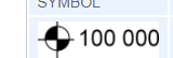
|
Job datum level |
stipulates the elevation at a specific point- the datum is the universal reference point. |
|
|
Special area reference |
References a separate diagram detailing a special area, this may indicate a separate dwelling such as granny flat or a pool area. |
|
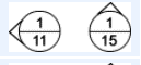
|
Elevation reference |
References a particular elevation diagram. This stipulates where the ground levels differ for example if there is a slope or dip in the ground. |
|
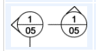
|
Section reference |
Usually associate with different plans for electrical, plumbing or slab pour. This will tell the relevant contractor the depth or measurements. |
|
|
Detail reference |
A special instruction to a contractor |
|
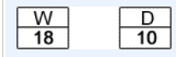
|
Window and door references |
Represents a particular window and door |
|
|
Graduated scale |
This is used to indicate the size and scale of the objects that are in the plans |
|
|
Compass |
Indicates the directions of the plans |
|
|
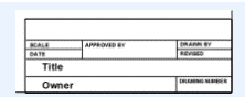
Title block |
The section that stipulates the specifics about the project, job details, builder, architect, dates, and so on. |


General plan view and fittings
|
Symbol |
Key |
|
|
Window |
|
|
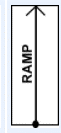
Ramp with indicating arrow |
|
|
|
|
|
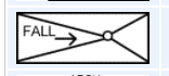
Fall/ drainage |
|
|
Bathtub |
|
|
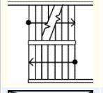
Shower stall, lines stipulate drainage points |
|
|
Basin |
|
|
Basin and vanity |
|
|
Toilet |


You may be surprised to know that there can be specific requirements around the height at which signage is hung. In a commercial environment, this can be to fulfil design and local government requirements. There can also be safety considerations – readability is one factor – signage hung at a particular height is more likely to be noticed. Another factor is whether the height of the sign is likely to cause a physical hazard, either to pedestrians or vehicles.
Suitable equipment/methods
- Information regarding height and other installation details would be located in plans and specs.
- Automatic level and staff to establish height from datum.
- Level could be transferred using a laser level or a spirit level and straight edge.
Sometimes at a building site, it becomes necessary to transfer the datum point. This may be because it will be damaged by the process of construction, it will be obstructed by building work or additional reference points are required. It may also be that you have been asked to establish a recovery point.
The datum point is a point of reference on a plan where the additional measurements can be made. The datum point is the position above sea level. The site datum is also known as a temporary benchmark and can be directly related to a nearby height.
When determining the datum points, the following are examples of suitable equipment/ methods.
Suitable equipment/methods
The datum could be transferred using:
- automatic leveller and staff
- laser level (where there is no obstruction)
- spirit level and straight edge (where there is only a short distance to transfer).
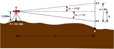
The following is an example of a site datum.
When recording the ground levels, a contour plan needs to be developed. After a site datum has been established, a graphical representation of the site is drawn up to display the land. The surveyor takes several levels (using an automatic leveller) of the site at what is known as grid spacing, the levels are then converted to reduced levels, also known as RLs). These levels are recorded and placed into the grid. The draftsperson will then come in and draw the lines to fit between the equal RLs ergo, the lines that represent the contour levels.
A contour plan is used to determine the fall of a block so that you can determine things like:
- floor levels
- excavation or fill requirements
- heights for services
- height retaining walls.
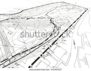
The following is an example of what a completed contour plan looks like.
When carrying out levelling tasks, positioning the offsets and recovery pegs need to be considered. A survey peg is used to help mark the measurements, and boundaries that have been determined at the point where the levelling has taken place on a block of land. A licensed surveyor must carry out these assessments, particularly when establishing the boundaries of the block of land. Unfortunately, there is not always a guarantee the pegs will stay in place, after they are positioned, which is why it is important to have the area double checked and ensure the pegs are in the correct position to avoid breaching the boundary of the block of land that is being built on. You must never assume the fences that may be erected around the land are the boundaries.
Fun fact!
In Australia, many councils require a boundary survey to take place before building is commenced to ensure the work is being carried out within the allocated block of land.
The use of the pegs stretches further than simply marking points on the land. They are also there to determine the following:
- soil levels
- foundation depth
- elevation
- slope distances.
The surveyor will carry with them a series of pegs that can be used to mark out the appropriate areas on the land. Each type of peg is used for a different point and come in a variety of sizes with various coloured tops. Commonly, surveyor pegs are made from wood, but they are also available in plastic or metal.
The following list outlines the types of survey pegs required to mark out the land, read through each type of peg before flicking through the image sliders that follow. Each image in the slider corresponds to the order of the following list.
Indicator survey pegs
An indicator survey peg is one of the most common types of surveyor pegs used. They are commonly made of wood and have the tops painted white, however, the colour painted on the top can be customised on request.
Boundary survey pegs
A boundary survey peg is used to determine where the boundaries are within the block of land. These sharp pointed pegs are used to mark the new boundary subdivisions on a block of land.
Dumpy survey pegs
These pegs are commonly used in conjunction with an automatic or dumpy level. They are used to accurately mark the points determined from the measurements that are taken from the automatic level.
Residential survey pegs
The residential survey pegs are used to mark out the areas in the land pertaining to the exact location of the residential property.
The pegs are all slightly different according to their purpose, this helps the surveyors and contractors determine what areas have been marked out and for what purpose.
The correct fall in drainage is essential in ensuring that sewerage, storm water or whatever it is that you are draining does not pool or block. The accurate recording and checking of drainage measurements against the plans and specs helps ensure that all drainage functions as it should.
Suitable equipment/methods
- Automatic level and staff
- Laser level
- Spirit level and flat edge
The pouring of the slab is one of the most important aspects of a build because it essentially sets the foundations of the build. Before the slab is poured, the area needs to be assessed to ensure the falls are accurate. Using a laser level or automatic level, the site is assessed, and the levels recorded. This needs to be accurate before the slab is poured because if it is not poured correctly, the entire project will be at risk. Often a concrete slab will require a fall so that water runs away from a building or structure.
Suitable equipment/methods
Tools that can be used include:
- laser level and receiver
- auto leveller and staff.
Formwork is the mould that holds concrete which sets to form the slab that a building sits on. It is essential that formwork is erected to the heights and levels which are indicated on the plans, because the foundations are what supports the building and holds it upwards. If the foundations are not right, the structural longevity of the building will become severely implicated.
Before the formwork can begin, a licensed surveyor must assess the building site to ensure the formwork is being erected on the correct land. Essentially, this is a second set of licensed eyes to ensure the task is carried out properly.
To determine the heights and levels that are needed for the formwork, ensure the plans and specifications have been thoroughly checked. Pegs are set up according to the boundaries that have been drawn up from the architect on the plans, the pegs are attached with string lines and nails to create the ‘outline’ of the house or building. Initially, a right angle needs to be established from the boundary point into the block of land itself. It is advised you use the appropriate measurements from the plans and specs to ensure accuracy. Pythagoras theorem is used in conjunction with the measurements on the plans to ensure you have an exact right angle to go by. You are then able to measure the rest of the building from this right angle, you will need pegs, ledgers, and string lines to set the profile of the building.
Suitable equipment/methods
You could use:
- auto level and staff
- laser level
- water level
- spirit level and straight edge
- combination of any or all of above.
By now you should be able to see, the foundations of the building are starting to take place, the slab, the formwork has been placed now it is time for the steel columns and masonry piers to be erected. In the same way that the slab for a building must be level and erected as per the plans and specs, so must the columns or piers that the building sits on.
Before the anchors of the steel columns and piers can be placed, the area needs to be level and the column set on levelling plates, levelling nuts (which is the preferred method). The desired location of these columns and peers should be identified on the plans and specifications after the groundwork has been carried out. Before the columns are erected, the relevant personnel, such as the site supervisor and surveyor will need to ensure the ground is accurately level, this way, the anchors are guaranteed to be secure and the ground enables them to hold the appropriate weight.
Suitable equipment/methods
Depending on the spacing of the piers or columns, suitable equipment could include:
- laser level
- auto level
- straight edge and spirit level.
The site clean-up is a step that is not to be missed. Cleaning up does not also ensure the tools and equipment you are using are kept in good working order, it also ensures the safety of workers and others who are onsite. When you are carrying out a site clean-up, consider the following:
- Follow the site’s procedures for safe environmental clean up
- Follow the site’s procedure to ensure that the clean up process does not put yourself or others at risk of injury or harm
- Always consider the principles of reduce, reuse and recycle
- Avoid contaminating stormwater when cleaning tools, equipment, materials and the work area
- Clean concrete from all tools and equipment
- Follow manufacturer instructions for cleaning and servicing tools and equipment
- Check tools and equipment for defects and/or damage before storing them
- Report any faults in tools and equipment and immediately remove them from service
- Check and clean PPE
- Clean and dry all tools and equipment before storing them
- Store tools and equipment securely and according to manufacturer specifications and instructions
- Store tools and equipment according to workplace specifications.