Welcome to the second module of your Level 3 Certificate in Electrical Pre-Trade.
You will begin by learning about the National Grid and how electrical energy is generated, transmitted and distributed in New Zealand. Safety while working at high voltage will be highlighted here.
Moving on, you will gain some understanding of the MEN system of electricity supply – the principles, configuration and reasons for using it. The focus remains on safety as you next earn about earthing and equipotential bonding.
During the first module you were introduced to some of the legislation regulating the New Zealand electrical industry. Module Two expands on this knowledge with particular emphasis on the AS/NZS 3000 Wiring Rules. This Standard sets out requirements for the design, construction and verification of electrical installations and is an essential guide for the day-to-day work of an electrician.
The final part of this module looks at your soft skills. These are the personal attributes you bring to the workplace that enable you to ‘fit in’. They include your personality, attitude, flexibility, motivation, and manners. Soft skills are so important that they are often the reason employers decide whether to take on, keep or promote an employee.
During the face-to-face sessions of Module Two you will continue learning about circuitry. You will have the opportunity to participate and run Toolbox meetings and the workshop enables you to practice the guidelines outlined in the various legislation you read.
This online self-paced resource contains daily ‘lessons’ as well as self-directed learning (SDL). The SDL reinforces and clarifies what you cover in the lessons, plus it helps you to prepare for the assessments. Make sure you commit to putting in the extra hours required – the final result will be worth it.
With the support of your Tutor, you’ll review your work, and receive feedback towards set development and performance objectives.
Credits: 12
Length: 14 days
Learning Outcomes:
- LO 1 - Demonstrate foundation knowledge of the national supply grid and safety with high voltage equipment.
- LO 2 - Demonstrate foundation knowledge of the MEN system.
- LO 3 - Demonstrate foundation knowledge of earthing and equipotential bonding.
- LO 4 - Demonstrate introductory knowledge of electrical legislation and industry governance bodies.
- LO 5 - Demonstrate an introductory knowledge of the fundamental principles of AS/NZS 3000.
- LO 6 - Demonstrate knowledge of electrical workplace ethics.
| Day 1 | Day 2 | Day 3 | Day 4 | |
|---|---|---|---|---|
| Course content |
Describe the NZ national electrical supply system. Ex 1 - 2 |
Dangers of high voltage Safety principles when working near high voltage. Ex 3-5 |
Review AC/DC. Ex 6 |
Principles, configuration and reasons for MEN earthing system. Ex 7-12 |
| Self-directed learning | Residential Power Bill | Research PPE for HV linesmen. | MEN system video. | MEN quiz |

What we're covering:
- How electricity is generated in New Zealand
- The National Grid
How is electricity generated in NZ? How does it reach our homes and workplaces?
In New Zealand, the process of getting electricity from start to finish through to your home or business goes through four different stages: generation, transmission, distribution and retail/user.

Generation
Generation is the process of creating electricity through different methods such as hydroelectric, geothermal, gas, wind, solar, coal and diesel. There are six major generation companies and over 200 generation plants, responsible for creating New Zealand’s electricity from a range of sources. The primary method is hydro which accounts for approximately half of New Zealand’s electricity generation. Over 80% of New Zealand’s electricity is generated from renewable sources.
Transmission
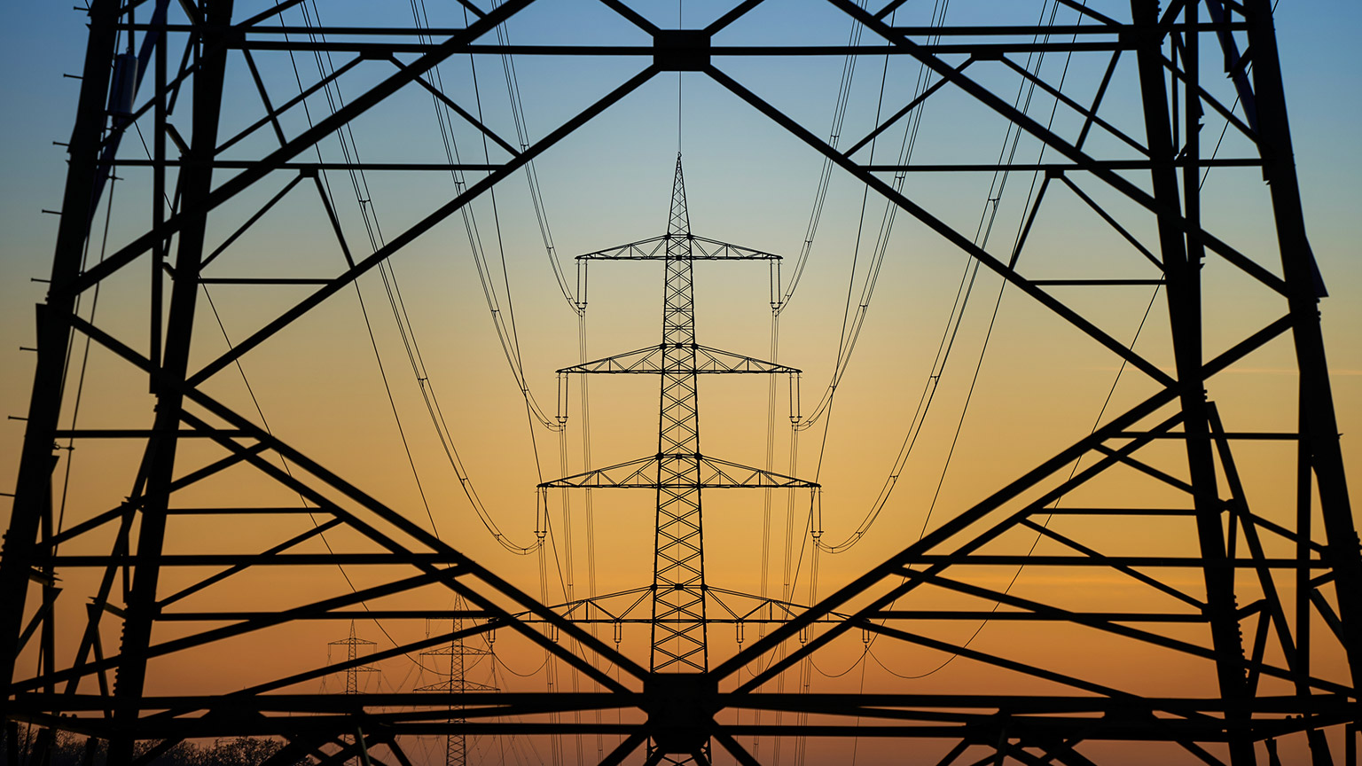
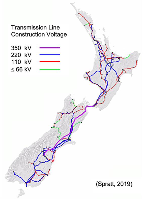
The electricity generated by power stations is transmitted through high-voltage transmission lines throughout the country. These lines make up a network known as the National Grid, consisting of more than 12,000 km of high-voltage transmission lines and more than 170 substations. The transmission network is carried by the big pylons and lines you may have seen throughout the countryside.
Some large industrial users of electricity receive their power directly from the national grid, but most consumers receive power via regional distribution companies.
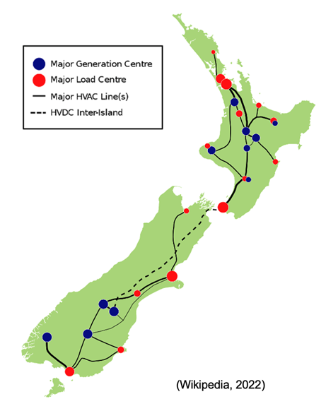
Most of the grid operates on the high voltage alternating current (HVAC) system, but there is also a high voltage direct current or HVDC link between the North Island and the South Island, which includes the Cook Strait cable. Voltages are typically 110 to 220 kV before being reduced (stepped down) at local substations to levels that make it suitable for distribution to commercial and residential areas.
Supplementing the major 110 or 220 kV transmission lines are sub-transmission lines and cables, operating at lower voltages such as 33 kV, 50 kV and 66 kV. These sub-transmission lines supply provincial towns and cities with electricity from the 220 kV grid, and also connect smaller power stations to the grid.
The national grid is owned, operated, maintained and developed by Transpower, a state-owned enterprise.
Most of New Zealand's electricity is generated from renewable energy sources (like hydro and wind). These energy sources are located in remote areas, a long way from where most of the population lives. The national grid is important in transporting electricity to where it is required.
Distribution
Power is transformed into lower voltages (25,000 volts or less) at substations and transported by distribution companies to homes and businesses. Before entering your home or business, the voltage is further reduced to 240/120 volts making it safe for typical residential and commercial use. Power is typically delivered to homes and businesses through overhead powerlines or underground cables.
Almost all consumer premises in New Zealand are connected to a distribution network. Keeping the network in reliable, working order is the job of distribution companies, or lines companies. Each region of NZ has an allocated company responsible for maintaining the power lines and power poles (both above and underground) in their area and making sure the lines have enough capacity to cater for each customer.
Retail
An electricity retailer is a company that buys power on the ‘electricity market’ at wholesale prices, packages it along with transmission and distribution costs, then on-sells it to consumers. The amount a retailer charges to the end user includes:
- The cost of the electricity supplied to the consumer – a variable charge calculated on usage. (The electricity meter at your house records the amount of electricity you use.)
- Charges for transmission and line charges – usually a fixed amount.
There are 31 energy retailers in NZ, all with different methods of charging, so it is worth shopping around to choose who to buy your power from.
How is Electricity Made?
Power stations contain large machines called turbines, which are turned very quickly. Large amounts of energy are needed to turn the turbines. This energy comes from burning fossil fuels, moving water or wind. The spinning turbine causes large magnets to turn within copper wire coils – these are the generators. The moving magnets within the coils of wire cause the electrons to move within the coils of wire creating electricity.
Steam turbine generators, gas turbine generators, diesel engine generators and alternate energy systems all operate on the same principle:
magnets + copper wire + motion = electrical current
The electricity produced is the same, regardless of the source.
Watch the following videos which look at the basics of power generation.
Exercise 1
This video shows you how to make your own Hydroelectric Generator. You will have the opportunity to make something similar in class with your tutor’s guidance. Make notes on the equipment you will need, and the steps required to make the generator.
How to generate electricity from water
Exercise 2
Match the energy source; convertor; and final stage to each method of power generation.
Self-Directed Learning
Study the residential power bill on the following page.
- Who is the retailer?
- What is the address of the house?
- How much is the daily fixed charge? What does this charge cover?
- What is an ICP number? Does this change if you move house?
- How does this company charge for actual electricity used?
- When is the most expensive time to use electricity? Why do you think this is?
- What does ‘controlled energy’ refer to?
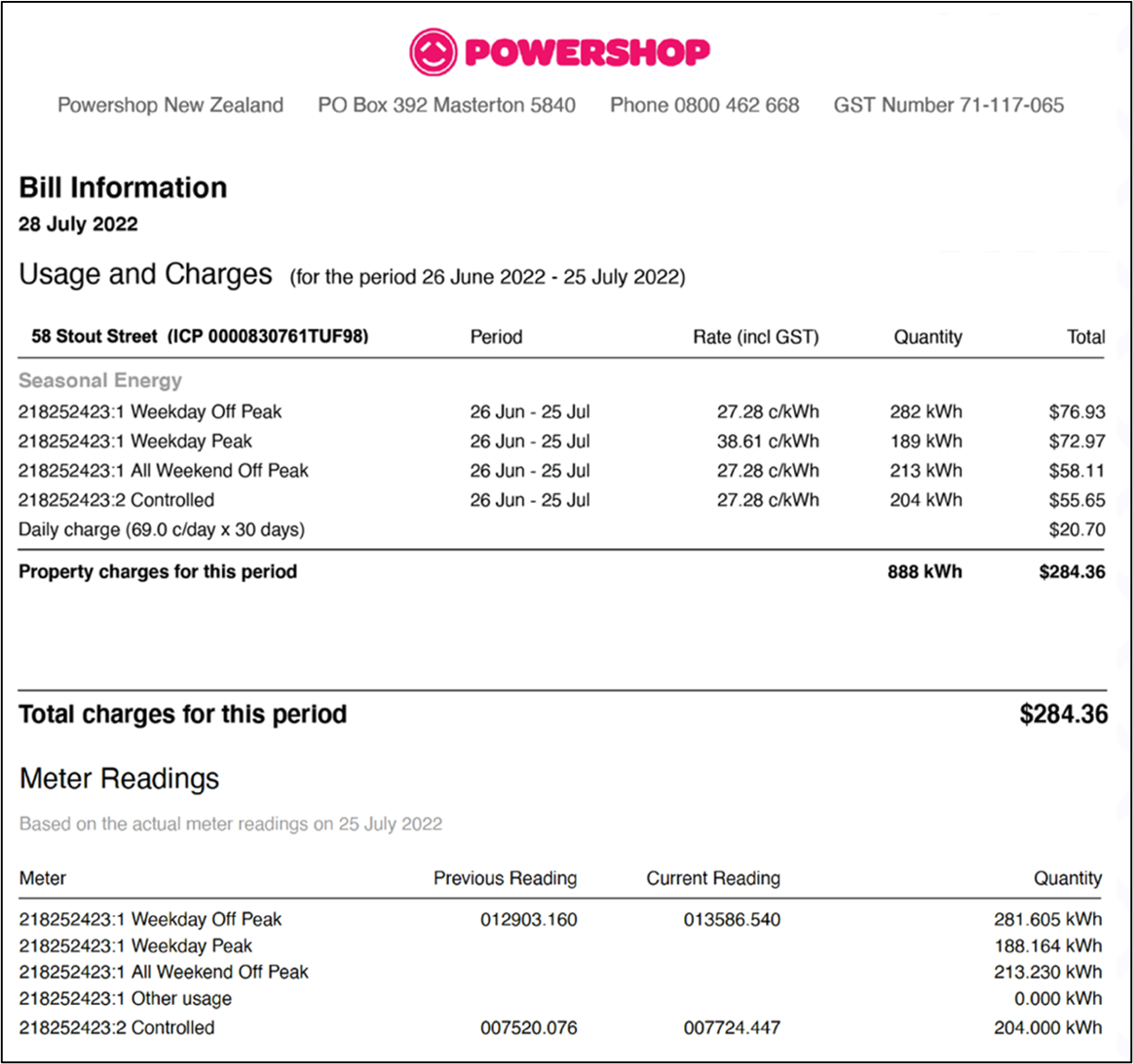
Now compare the rates charged by Powershop either to your own provider, or to Vector below.
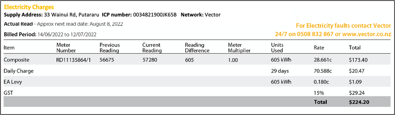
This bill includes a charge for the Electricity Authority Levy.
- What does this cover?
- What is the daily charge?

What we are covering:
- what high voltage lines are
- where they are found
- the dangers of high voltage
We are going to begin this lesson with a sobering story about a young Australian electrical worker who tragically lost his life when he was exposed to arcing electricity from high voltage lines when performing a routine electrical task. You can watch 'Young worker safety: Tim's story' here.
According to the Electricity (Safety) Regulations 2010, high voltage (HV) means voltage exceeding 1,000 volts AC or 1,500 volts ripple-free DC.
(Ripple voltage refers to the amount of AC voltage that appears on a DC voltage.)
High voltage is used for electrical power distribution. The electricity generated at the power plant passes through a ‘step-up’ transformer converting it into high-voltage electricity (110 or 220 kV) before travelling around the national grid. Once the electricity reaches its destination, a second transformer ‘converts the electricity back to a lower voltage safe for homes and businesses to use.
Exercise 3
Carry out some research to find answers to these questions, then write a brief explanation for each in your own words.
- Why is power is transmitted at high voltage?
- Why is power transmitted as AC rather than DC?
Exercise 4
Pylons – or electricity transmission towers – are the structural supports that carry the network of high-voltage overhead power lines around NZ. Pylons are usually made from galvanised steel, due to its strength. Transmission lines consist of uninsulated aluminium/steel or aluminium alloy stranded conductors. These conductors are insulated from the tower by porcelain or glass insulators.

Since transmission lines are uninsulated, it is important that nothing come close enough to cause an electric arc. An arc can start a fire and cause a serious outage. At the voltages used for power transmission, a tree doesn’t need to touch the line to create an arc.
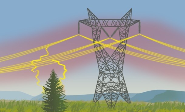
The average height of pylons in our national grid is 55 m. The heavy electric cables must be kept at least 11.5 m above ground to maintain safety from the powerful electric and magnetic fields generated around them.
Shorter, wooden poles have a limited voltage capacity and run a fire risk if exposed to extreme heat. They require regular maintenance to ensure that they are not rotting or deteriorating. Wooden utility poles commonly carry distribution lines.

Note: Towers carrying live conductors should never be climbed in case the tower is energized.
The Dangers of High Voltage
In Module 1 we looked at the general hazards of electricity, i.e., electric shock, burns, fire and arc or explosion. Similar hazards are present at high voltage; however, the possibility of serious injury or damage is greatly increased. For example, a person providing a path for a high voltage through their body will be subject to burns but is also likely to burst into flame, owing to the heating effect of the current being passed through him or her.
High voltage conductors are likely to carry high currents and therefore run at much higher temperatures than low voltage conductors, so extra care must be taken to prevent burns or fires.
The most significant electrical shock and fire hazards are due to the fact that at high voltages a current can arc or “jump” (like lightning) across quite significant spaces — at 25 kV a current can jump 25 cm. Direct contact with an electrical conductor is not necessary for a person to receive a shock or for a fire to start from the discharge.
Watch the short clip of an electrician disconnecting high voltage wiring - the Arc Flash almost touches him.
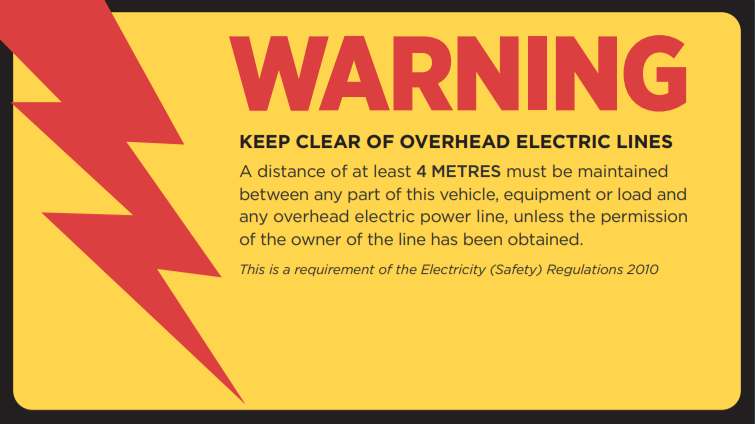
You should avoid any machinery, people or equipment coming within a ‘safe distance’ of transmission lines. The New Zealand Electrical Code of Practice for Electrical Safe Distances (NZECP 34:2001) sets these distances at within 4 m of overhead power lines and 6 m of overhead transmission lines.

Contact with, or near proximity to, a high voltage conductor can occur when operating vehicles with a long boom, e.g., a crane or mobile elevated work platform, or by people carrying long conductive objects, e.g., metal ladders or scaffold poles.
You should also take care when working at height – your initial safe distance may be reduced once you commence work at an elevated level.
Given the high risks involved, there should always be at least two people present during high voltage work, with both being aware of the responsibilities they hold and the emergency procedures which may need to be carried out.
The physical risk controls required for working on high voltage plant or equipment must be explicitly specified by the authorized person in the permit to work.
Isolation should be by means of a device that has a safe isolating gap between live parts and those that have been made dead for work to be carried out. Earthing conductors at the point where the supply is disconnected are essential and additional earths may be necessary at the place of work.
General physical risk controls when working in the vicinity of high voltage should include:
- Isolation of the plant or equipment being worked on, including the means to ensure this remains isolated, such as locking off.
- Discharge of conductors and equipment to remove any residual electrical charge that could be present.
- Earthing of the part of the electrical system being worked on to ensure that a dangerous voltage cannot occur on it.
- Caution during storms or strong winds - transmission towers may become energized due to the conductivity of water and live conductors may fall down.
Exercise 5 (part 1)
Exercise 5 (part 2)
Self-direct Learning
Equipment and conductors that carry high voltage have specific safety requirements and procedures. Find out what PPE must be worn by linesmen working at HV.
Post your answers on the class forum.

What we're covering:
- alternating and direct current
- single and multiphase power
- delta and wye configurations
Before learning about single phase and multiphase power supply systems it is important to check your understanding of the two types of electric current - direct current (DC) and alternating current (AC).
Direct Current
In Direct Current, the voltage is always constant, and the electricity flows in a certain and constant direction (from high electron density to low electron density).
DC is unsuitable for power transmission because changing the direction and voltage is expensive and difficult to achieve. In addition, DC is unable to travel long distances as it begins to lose its energy.
DC can store electricity. Everything that runs on a battery and uses an AC adapter while plugging into a wall, or uses a USB cable for power, relies on DC. Examples include cell phones, electric vehicles, flashlights, flat-screen TVs (AC is converted to DC inside the TV).
Alternating Current
In Alternating Current, the voltage periodically changes from positive to negative and from negative to positive, and the direction of the current changes accordingly. On an oscilloscope, DC and AC are represented in the following way:
AC can be identified in a waveform called a sine wave. These curved lines represent electric cycles. The number of periods or cycles per second is called frequency. The SI unit for frequency is the Hertz (Hz). One hertz is the same as one cycle per second. (Notice the frequency of DC is zero.)
AC, with its cyclic positive and negative voltage, has the advantages of:
- Easily transformed (stepped-up or -down).
- Easily shut down while power is flowing.
- Less power loss due to high voltage transmission.
- No concerns about positive and negative voltage.
Electricity produced at power plants and sent to households and work locations is transmitted as AC. AC is used ‘as-is’ for motors not requiring delicate control, such as vacuum cleaners and ventilation fans, but in motors for air conditioners, washing machines, refrigerators, etc., inverters are used for the fine control of AC power.
Exercise 6
Single Phase and Multiphase Power
Alternating current is used to transport electric power all across the electric grid, from generators to end users. An AC circuit can be configured as a single-phase or a three-phase (multiphase) system. Single-phase systems are simpler and can deliver enough power to supply an entire house, but three-phase systems can deliver much more power in a more stable way, which is why they are frequently used to supply power for industrial applications.
Watch this video explaining how Three Phase Electricity works.
Single phase is the preferred method to supply current to individual homes or offices, so as to distribute the load evenly between lines. Single phase power systems consist of only two wires - the phase (also called the Line/Live/Hot) and the neutral wire. Current flows through the phase wire to the load and the neutral wire provides the return path.
In New Zealand single phase voltage is 230 volts and the frequency is 50 Hz. A single-phase power supply is the preferred method to supply current to individual homes or offices, so as to distribute the load evenly between lines.

Because of the structure of a single-phase system, there are peaks and dips in power that change during the cycle. They cannot transfer as much power to loads as multiphase systems do and they are more prone to power failures. Their advantage however is to allow the use of much simpler networks and devices.
Multiphase systems use or generate three or more alternating voltages of the same frequency but differing in phase angle. Three-phase electric power consists of three conductors (or four if a neutral wire is included), which each carry an alternating current of the same frequency and voltage amplitude, but with a relative phase difference of 120°. These systems are the most efficient at delivering large amounts of power and are commonly used in high-voltage power transmission. Power delivery in three phase supply is always steady and consistent since the peaks and dips of the three AC signal are compensated by each other and the less chance of an overall fault is low because even if there is fault in one or two phases, the remaining phase(s) will continue to deliver power.

Once sent to a household outlet, three-phase power is converted to one phase along with the voltage conversion.

Delta and Wye Configurations
In a three-phase power supply during one cycle of 360 degrees, each phase would have peaked in voltage twice. Also, the power never drops to zero. this steady stream of power and ability to handle higher loads makes a three-phase supply suitable for industrial and commercial operations, there are two types of circuit configuration in a three-phase power supply. The Delta and the Star (or Wye) configurations enable a circuit to present an equal or balanced load to all three phases.
An important difference between the two configurations is the number of nodes - Delta has three (one node for each phase), and Wye has four. This fourth node allows for the connection of a neutral wire. A neutral wire must be available if one of the phases is going to be used to power equipment that runs on single-phase AC.
The Wye configuration is the most commonly used for power distribution. It can supply both phase voltage - the single-phase voltage supplied to homes, and line voltage - for powering larger loads. This way, both homes and industrial machinery can be supplied with the same transmission line.

In Delta there is no neutral wire. Delta connections offer greater reliability and are typically used to power three-phase loads, in particular all the high voltage systems as well as large electric motors.

Self-directed Learning
Read this information about the MEN system and watch the video. This will help you to get your head around the content of the next lesson.

What we're covering:
- earthing systems
- the MEN system configurations
- the MEN system components
Two forms of protection against electric shock are recognized. The first of these is termed ‘basic protection’, which is protection against direct contact with live parts and the second is ‘fault protection’, which is protection against indirect contact with a conductive part of an apparatus which is normally dead and earthed, but which has become live due to a fault.
- Basic protection, or direct-contact protection, includes measures to prevent contact with live parts, in particular protection by the insulation of live parts and protection by means of barriers or enclosures.
- Fault protection, or indirect-contact protection can be achieved by automatic disconnection of the supply if the exposed-conductive-parts of equipment are properly earthed.
In an electrical network, an earthing system is a safety measure which protects human life and electrical equipment.
Earthing systems differ from country to country, but with few exceptions, New Zealand uses the Multiple Earthed Neutral (MEN) system for electrical distribution and installations.
Refer to these two pieces of legislation:
- Electricity (Safety) Regulations 2010 (Section 1.4).
- AS/NZS3000:2018 (Australian/New Zealand Wiring Rules).
“MEN is a system of earthing in which the parts of an electrical installation required to be earthed in accordance with this Standard are connected together to form an equipotential bonded network and this network is connected to both the neutral conductor of the supply system and the general mass of earth.”AS/NZS3000:2018 Clause 1.4.83
In the MEN system of earthing the low voltage neutral conductor is used as the low resistance return path for fault currents and where its potential rise is kept low by having it connected to earth at a number of locations along its length.
The neutral conductor of the distribution system is connected to earth at:
the source of supply (either the generating station or the substation from which electricity, at the voltage at which it is delivered to the consumer, is derived); and
regular intervals throughout the supply system; and
every electrical installation connected to that system.
Characteristics of the MEN System
- The main earthing electrode is installed in a soil that is effectively conductive.
- The neutral of the supply transformer must be earthed.
- A link connects neutral and earth in the main distribution panel.
- All exposed metal parts in the electrical system are earthed.
Earthing Configurations
The International Electrotechnical Commission (IEC) uses five basic methods of earthing systems, abbreviated to TN-C, TN-S, TN-C-S, TT and IT, where:
- T stands for earth or terra.
- N for neutral.
- I for isolated.
- S for separate.
- C for combined.
So, in a TN-C (Terra Neutral – Combined) system, Earth and Neutral are combined (also referred to as PEN – protective earth-neutral), whereas in a TN-S system, separate conductors for Earth and Neutral run to consumer loads from the site’s power supply.
A TN-C-S system is very common as it allows the single-phase loads to be supplied by phase and neutral with a completely separate earth system connecting together all the exposed conductive parts before connecting them to the PEN conductor via a main earthing terminal which is also connected to the neutral terminal.
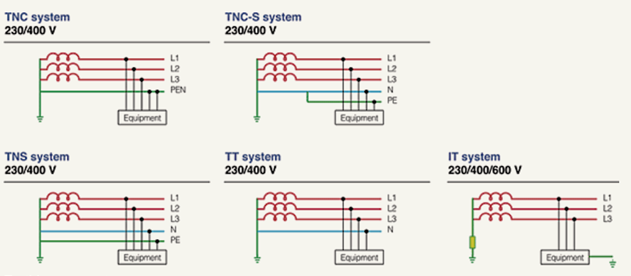
According to AS/NZS3000 TN-C is used for distribution, and (generally) TN-S within the installation. The usual point for the change from TN-C distribution to TN-S installation happens within the installation at the Main Switchboard, specifically at the MEN link. When considering the system as a whole, it is treated as TN-C-S. It is a feature of TN-C systems that the N is earthed at origin and at intervals along its length. The term "MEN" specifically refers to this fact that the N is earthed at multiple places.
Watch this video explaining the earthing arrangements TN-C-S in a single-phase installation.
TN-C-S System Earthing
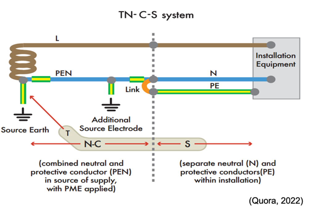
The TN-C-S system, shown above, has the supply neutral conductor of a distribution main connected with earth at source and at intervals along its run. This is usually referred to as protective multiple earthing (PME). With this arrangement the distributor’s neutral conductor is also used to return earth fault currents arising in the consumer’s installation safely to the source. To achieve this, the distributor will provide a consumer’s earthing terminal which is linked to the incoming neutral conductor.
Components of the MEN System
The MEN system of earthing requires an electrical connection to be made between the protective earthing system and the neutral connections of the installation, usually made at the main neutral link in the main switchboard of the installation (MEN connection). The effectiveness of the system depends on:
- The incoming main neutral conductor.
- The MEN link between the main earth terminal bar and the main neutral conductor bar.
- The connection of the main earthing conductor to the earth electrode.
Why is MEN so Important?
- It makes the circuit safe – in an electrical fault where the neutral conductor is disconnected and the active conductor is connected to the exposed metal network, the current flows through the earth conductor to the switchboard, which allows the protective device (such as fuses or circuit breakers) to open circuit and make it safe. In this way the MEN system makes it safe.
- It helps during earth fault currents – When there are earth fault currents, the MEN system uses the network neutral conductor as the conductive path for installation. It is called the ‘earth fault current’ because the fault current of an electric appliance or an equipment goes to the earthed frame.
- It provides an environment for circuit protection to operate correctly – these faults currents should be large so that the protective devices (such as fuses and circuit breakers) can operate. When an Active to Earth fault occurs, the fault path is through the low resistance circuit to the MEN link to the source of power (such as a generator or transformer). The neutral conductor provides the low resistance path so that the power can return. In the absence of the MEN link, the fault current would return via ground.
- It prevents fatal voltage on electrical appliances and exposed metal parts - Earth has a higher resistance than the MEN/neutral conductor path. Thus, the fault current’s capacity would be limited to a degree that it might not be able to operate the protective devices. As a result of this, a fatal voltage can remain on the metallic enclosure of equipment or electrical appliance.
(Electricians Success Academy, 2020)
Despite its popularity, the MEN arrangement could be hazardous if the PEN conductor becomes an open circuit in the supply because the current would not have an immediate path back to sub-station level. Because of this, there are certain installations where it is not allowed to be used – including petrol stations, building sites, caravan parks and some outbuildings.
Exercise 7
Exercise 8
Exercise 9
Exercise 10
Exercise 11
Exercise 12
Self-directed Learning