| Day One | Day Two | Day Three | Day Four | |
|---|---|---|---|---|
| Course Content |
Step Voltage & Touch Voltage Ex 13-15 |
Earthing & equipotential bonding. Ex 16-17 |
Earth continuity and disconnection times of protective devices. Importance of fast disconnection times. |
Industry governing bodies & agencies. Ex 18 |
| Self-directed Learning | Nomogram Exercises | Nomogram Exercises | Revision exercises | Revision exercises |
What we're covering:
- what step and touch voltage are
- power systems earthing
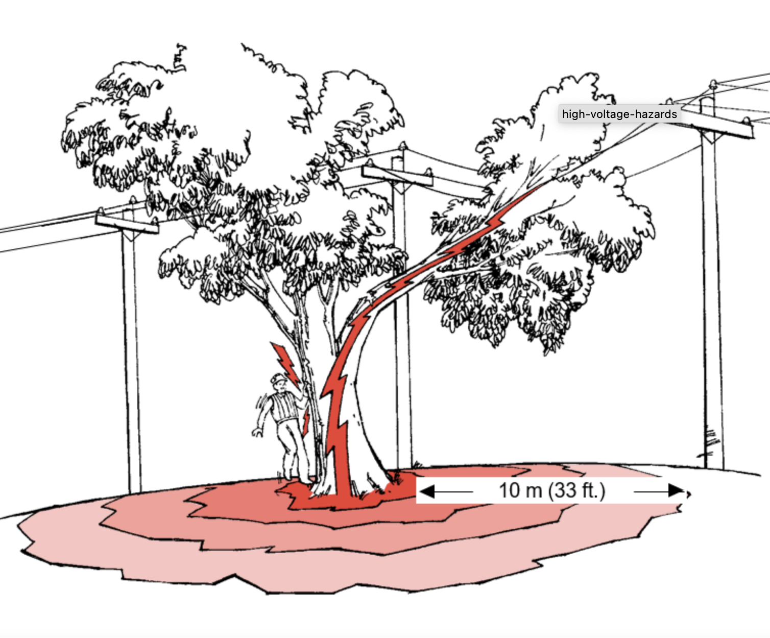
Watch this video explaining Step Voltage and Touch Voltage.
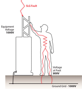
Does the picture below show step or touch voltage?
Refer to NZECP: 35:1993 for Power Systems Earthing. This code of practice is intended to provide guidance on acceptable methods for determining the safety of earthing systems associated with works. (Links and explanations for various New Zealand Electrical Codes of Practice (ECPs) can be located at the WorkSafe website.
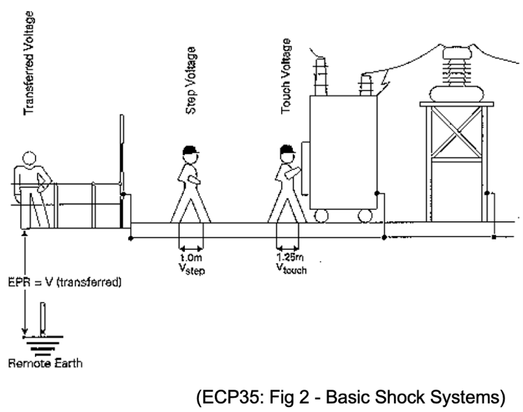
Section 1.2.14 Step voltage means the difference in surface potential experienced by a person bridging 1 metre with the person’s feet apart, without contacting any other earthed object.
Section 1.2.17 Touch voltage - means the voltage which will appear between any point of contact with uninsulated metalwork located within 2.5 m from the surface of the ground and any point on the surface of the ground within a horizontal distance of 1.25 m from the vertical projection of the point of contact with the uninsulated metalwork.
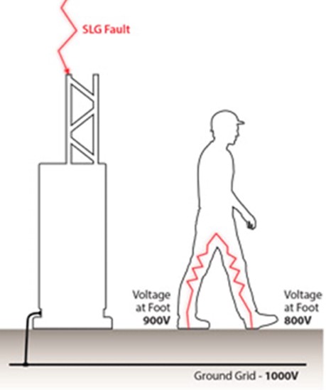
When current flows from an overhead conductor to the earth, a high-voltage condition is created and a voltage gradient will occur based on the resistivity of the soil, resulting in a voltage difference, or potential difference, between two points on the ground. This can cause voltage difference between a person’s feet.

| The diagram below represents a “Step Voltage” of 100 Volts. | The diagram below illustrates a “Touch Voltage” of 200 Volts. |
 |
 |
Exercise 13
Self-directed Learning (Lesson 5 & 6)
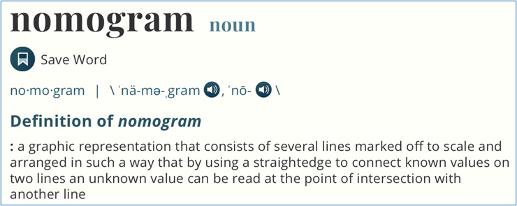
Sections 6.7.1 and 6.8 of the ECP35 refer to a Nomogram for calculating minimum conductor size. The Merriam-Webster dictionary defines a nomogram as:
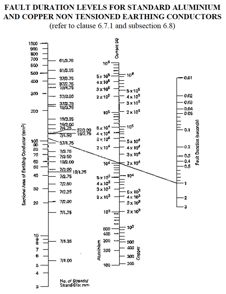
6.7 EARTHING CONNECTIONS 6.7.1 Earthing conductors used for making connections of fittings to earth shall have a capacity not less than the size calculated on the Nomogram in figure 4, page 19 of this Code. The clearance times specified in the Nomogram relate to the protection associated with the portion of high voltage line and the distribution centre fuses.
6.8 LOW VOLTAGE EARTHING CONDUCTORS ASSOCIATED WITH LV SYSTEM Conductors used to connect the neutral terminal or bar of a LV system to the earth bar, or the neutral conductor of an outgoing overhead line, shall not be smaller than that calculated in the Nomogram of figure 4, page 19 of this Code based on the expected fault current and duration.
The nomogram contains lots of numeracy to get your head around - before you even begin using it for its intended purpose. All those things you thought you’d never use when you were in school!
Let’s begin by looking at each of the three parallel lines:
- Line 1 – The LHS (left hand side) scale is sectional area of earthing conductor (measured in mm2). The RHS (right hand side) scale on this line is the number of strands / strand diameter (measured in mm).
- Line 2 (central line) – This scale measures current (in amps). The LHS values refer to aluminium and the RHS values are for copper. Some of the larger numbers are expressed in standard form.
- Line 3 – The RHS scale reads fault duration, measured in seconds.
Standard Form
Sometimes we must work with very large or very small numbers e.g., the speed of light is 300,000,000 m/s. The mass of a dust particle is 0.000 000 000 753 kg. Scientists have developed a method to express very large numbers. This method is called Scientific Notation or Standard Form and is based on powers of 10.
Watch this video if you are a bit rusty on standard form. The first demonstrates how to convert a number into standard form and the second shows how to convert standard form back to ordinary decimal numbers.
Exercise 14
Test yourself! On a piece of paper, write down the answers to the following sets of questions. When you are happy with your answers, look them up online.
Set A - Write the number(s) from questions 1-5 below in standard form.
- There are 97,000 km in blood vessels in the human body.
- The human eye blinks an average of 4,200,000 times a year.
- A computer processes a certain command in 15 nanoseconds. In decimal form, this number is 0.000 000 015 ns.
- The cosmos contains approximately 50,000,000,000 galaxies.
- The mass of the sun is roughly 989,000,000,000,000,000,000,000,000 T.
Set B - Write the number(s) given in scientific notation in questions 1-5 below in ordinary decimal form.
- The age of earth is approximately 4.5 x 10⁹ years.
- The weight of one grain of salt is approximately 5.85 x 10⁻⁵ g.
- A human body contains approximately 2.6 x 10¹³ blood cells.
- A major NZ company made $1.43 x 10⁸ profit in the year 2021.
- In the year 2021, British Petroleum posted profits of 16.4 billion (US) dollars. Write this profit in standard form.
Circle Radius, Diameter and area
Refresh your knowledge about circles by watching these videos:
You will also find some useful revision questions here along with answers.
Cross-sectional Area
Electrical wire is usually round in cross-section and comes in two basic varieties: solid and stranded. Solid copper wire is a single strand of copper the whole length of the wire. Stranded wire is composed of smaller strands of solid copper wire twisted together to form a single larger conductor.
The benefit of stranded wire is its mechanical flexibility, being able to withstand repeated bending and twisting much better than solid copper (which tends to fatigue and break after time).

Wire size can be measured in several ways however it is the cross-sectional area that matters most regarding the flow of electrons. The nomogram details sectional area as well as number of strands and strand diameter.
Using the Nomogram
Look at the example in ECP35:
What is the minimum standard size copper conductor required for a calculated fault current of 20,000 amperes and a fault clearing time of 1 second?
Calculation:
- Draw a straight line through 1 second on RH scale and 2 x 10⁴ (20,000) on right side of the centre scale (right side since it is copper and not aluminium).
- Extend the straight line to cut the scale on the left. The nearest conductor size above the point of intersection is 7/4.50 i.e., 7 strands/4.5mm per strand.
Exercise 15
Download this worksheet and fill in the gaps on the table by reading the correct figures from the nomogram. Ask your tutor to check your answers when you are next on campus.

What we're covering:
- difference between earthing and equipotential earthing
- grounding and bonding
Both earthing and equipotential bonding are intended to prevent electric shock.
Earthing protects you from an electric shock by providing a path (a protective conductor) for a fault current to flow to earth. It also causes the protective device (either a circuit-breaker or fuse) to switch off the electric current to the circuit that has the fault.
The MEN system takes care of most of the electrical installation (electrical cables and equipment), however AS/NZS 3000, 5.4.6 Structural Metalwork and Conductive Building Materials, introduces the requirement to earth ‘at risk’ conductive building elements. (Conductive parts at risk of coming into contact with live cables/equipment or damaged cables.) Examples of what might need to be earthed are:
- Structural steel frames or members.
- Light steel structural framing.
- Exposed conductive materials, like metal sink/tub or vanity benches etc, with electrical units or equipment in contact.
- Depending on the situation and risk other conductive items like metal cladding/lining, roofing etc.


"Equipotential Bonding is intended to minimise the risk associated with the occurrence of voltage differences between exposed conductive parts of electrical equipment and extraneous conductive parts". (AS/NZS 3000, Section 5.6.1.)
Bonding together conductive parts allows the potential to be almost the same and therefore safer. Without equipotential bonding, if you touch electrical equipment with a fault and also touch metal which is not part of the electrical installation, the potential voltage will not be equal, and in trying to be equal it may want to go to earth through you!
Note: metalwork associated with the electrical installation is known as exposed, while metalwork not associated with the electrical installation is termed extraneous.
What are some examples of extraneous conductive parts requiring equipotential bonding?
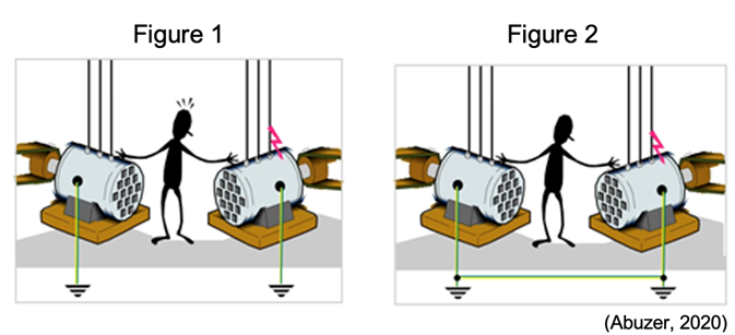
Consider two motors (as shown in Figures 1 and 2) fed by two different power systems (one Low Voltage and the other Medium Voltage). Each motor is earthed.
A person standing on earth (and insulated with respect to the earth) touches both motors simultaneously.
- If an earth fault occurs at one motor, the motor body will become alive, and the person will experience a shock. (Figure 1.)
- When the motor bodies are bonded (Figure 2), any potential difference will be minimised due to the connection and the person will not receive an electric shock.
Watch this video explaining Grounding and Bonding.
Exercise 16
Exercise 17
Self-directed Learning
- Complete the nomogram exercises from Lesson 5.
- Can you complete this puzzle?


What we're covering:
- earth continuity
- leakage and insulation testing
- RCDs
- disconnection times
AS/NZS3000:2007 Electrical Installations Section 8 prescribes the mandatory tests for electrical installations to comply with the regulations, and Clause 8.3 Testing lists the mandatory tests required and broad testing procedures.
In addition to the required visual inspection, the mandatory test requirements for electrical installations are:
- Continuity of the earthing system* (earth resistance of the main earthing conductor, protective earthing conductors and bonding conductors).
- Insulation testing, achieved by either measuring insulation resistance, or leakage current.
- Polarity - confirmation of the correct polarity of live connections in cord sets/cord extension sets with rewireable plugs or rewireable connectors/cord extension sockets.
- Correct circuit connections.
- Verification of impedance required for automatic disconnection of supply (earth fault-loop impedance).
- Operation of RCDs.
Earth Continuity
The Earth Continuity Test, (AS/NZS 3000 8.3.5) is carried out between exposed metal parts of the electrical installation and the earth bar. It is one of the most common product safety tests. It is performed on a product’s electrical grounding system. Testing is mandatory for: Class I equipment; EPODs (electric portable outlet devices); Cord Sets and Extension Sets and RCDs - residual current devices not within the scope of AS/NZS 3003 and NZS 6115.
Earthing continuity is also covered by AS/NZS 3760:2010 2.3.3.:
To confirm that the resistance of the protective earth circuit is sufficiently low to ensure correct operation of the circuit protecting device, the continuity of the protective earthing conductor from the plug earth pin to accessible earthed parts of Class I equipment shall be checked. The continuity of the protective earth conductor between the earth pin of the plug and the earth contact and every outlet(s) of cord sets, cord extension sets, EPODs and PRCDs shall be checked. Such equipment shall be tested in accordance with Appendix D and shall have a measured resistance of the protective earth circuit, or the protective earthing conductor which does not exceed 1Ω.
It is the grounding system that protects the user from a shock hazard during an electrical fault condition. The test identifies excess resistance in the grounding system that could limit the effectiveness of the ground to perform its intended function.
Keep in mind these two objectives:
- Low Resistance: The main objective of the Earth Continuity Test is to verify that the protective ground system has minimal electrical resistance. If an internal electrical fault occurs in the product while in use, ideally all fault current will flow to ground (earth) rather than through the person. Also, by keeping ground resistance low, the fault current remains high, tripping the circuit breaker or fuse as soon as possible.
- Reliable at High Current: To ensure the grounding system continues to operate as intended during a fault condition. The grounding system must be able to hold the fault current until the overcurrent protection for the product is tripped (i.e., circuit breaker).
During the continuity test, a digital PAT/multimeter sends a small current through the circuit to measure resistance in the circuit. If the flow of electrons is not continuous due to damaged components, broken conductors or high resistance, the circuit is considered “open.” Continuity testing must only be attempted when voltage is NOT present in the circuit being tested.
Earth connections need regular testing as they can easily be damaged by a range of factors such as corrosion, loose connections, insulation being crimped under screw terminals or too small a wire being used.
If the earth connection is missing or damaged then an important protection mechanism is diminished or even non-existent, creating a significant safety hazard.
Watch these videos about the Earth Continuity Test and make notes for your own reference.
- Earth Continuity Test
- Grounding vs Bonding: Grounding Series (Part 3)
- Cable Testing: How to test continuity and insulation resistance.
- Electrical Capstone Practical Exam Fault Finding-Earth Continuity
Your tutor will show you how to carry out an earth continuity test in class. Make notes about the steps you should follow.
Visual Inspection
Around 90% of faults can be found by inspection alone. Visual Inspection testing involves checking appliances, accessories, connectors, plugs or extension outlet sockets for all manner of other things to ensure they are safe to operate. You will have the opportunity to carry out visual inspections in the workshop.
Earth Leakage Test and Insulation Resistance Test
The integrity of the insulation between live parts and other parts is tested by measuring the leakage current value, or by measuring the insulation resistance value:
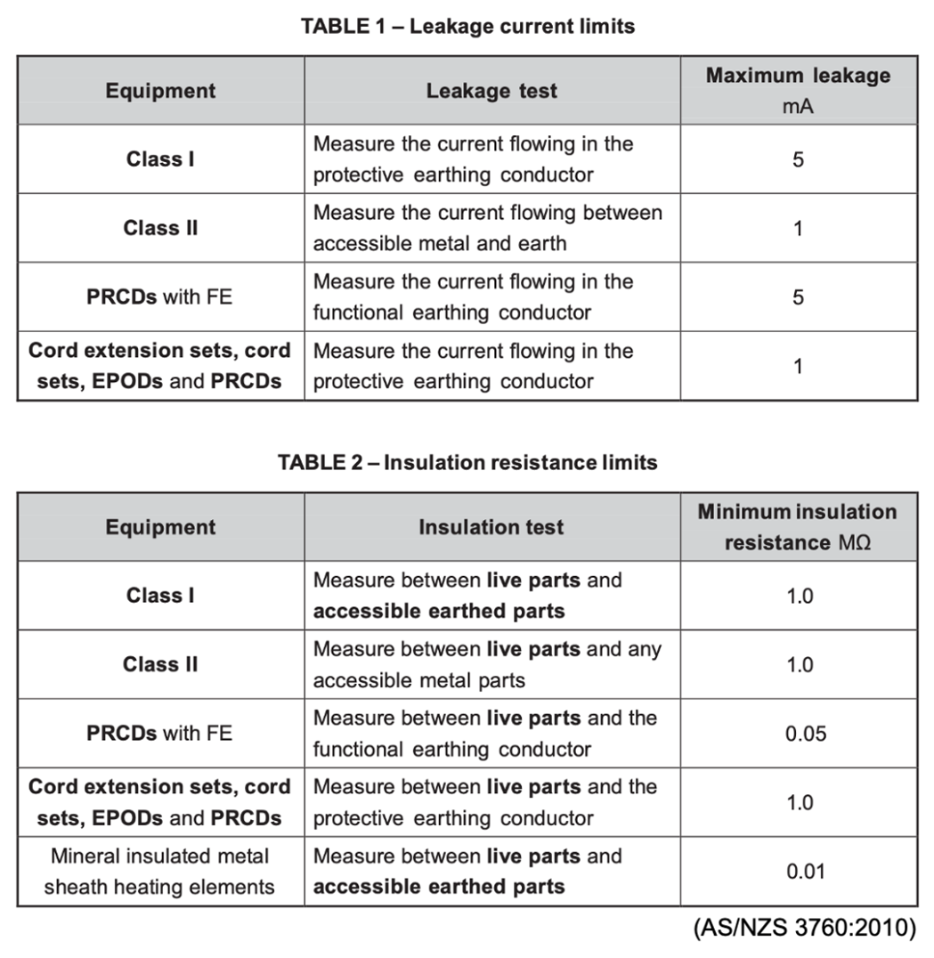
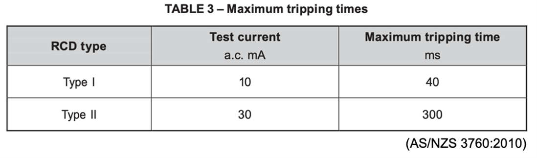
Residual Current Devices (RCDs)
An RCD is an electronic sensing device which constantly monitors the balance of the current flow in the live and neutral conductors to ensure that should even a minor leakage occur the RCD will switch off the power within 300 milliseconds (for personal protection RCDs) i.e., in less than the time of a single heartbeat -which could mean the difference between life and death.
As well as testing for earth continuity and insulation /leakage, RCDs should have a Trip Time test performed on them at the time period specified in AS/NZS3760:2010.
Disconnection Times
The disconnection time, or time taken for a circuit breaker to cut off the electrical supply during a fault, is a big factor in someone surviving an electrical shock. The quicker a circuit can disconnect the supply during a fault, the safer the circuit is.
Be aware however that the longest disconnection times for protective devices, (leading to the longest shock times and the greatest danger), are usually associated with the lowest levels of fault current, and not, as is commonly believed, the highest levels. Why is that do you think?
AS/NZS 3000:2018 1.5.5.3 states the maximum disconnection time for 230/240 V supply voltage shall not exceed the following:
- 0.4 s for final subcircuits that supply -
- socket outlets having rated currents not exceeding 63 A;
- hand-held Class 1 equipment; or
- portable equipment intended for manual movement during use.
- 5 s for other circuits including sub-mains and final subcircuits supplying fixed or stationary equipment.
Maximum disconnection times are set according to the level of risk and will vary for different voltages and installation conditions. 0.4 seconds is roughly the maximum time that 95% of people should be exposed in a left hand to feet shock for a voltage of around 240 V A.C., with a low risk of irreversible physiological side effects, under normal conditions and operating in a "TN" system.
See AS/NZS 3000:2018 Appendix B for detailed description of Disconnection Times.
AS/NZS 4871.1:2012 Figure 1 shows the maximum duration of human exposure to prospective touch voltages that do not usually result in result in harmful physiological effects, under normal conditions (Curve L) and wet conditions (Curve Lp).
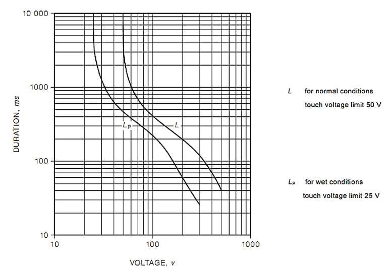
The curves represent the 50 Hz voltage/time duration limits for the majority of the population that will not result in fibrillation (and so electrocution). They are well beyond the threshold of perception and, at a minimum, will result in a painful shock, involuntary movement and loss of normal muscle control that may result in substantial injury as a consequence. They may only be considered ‘safe’ in that the majority of people are unlikely to fibrillate and will recover from the shock without assistance or lasting physiological damage. (World Coal, 2017)
For normal conditions a touch voltage of 50 V can be sustained by a person indefinitely, whereas a touch voltage of 100 V cannot be sustained and must be disconnected.
AS/NZS 3760:2010 (to be superseded by AS/NZS 3760:2022 in June 2023) specifies in-service safety inspection and the testing protocols and criteria that satisfy these obligations and provides a cost-effective approach to safety without jeopardizing personnel safety or involving excessive equipment downtime.
The standard enables persons responsible for the safety of electrical equipment in the workplace to instigate an inspection and testing programme to achieve that aim. It also enables persons undertaking the inspection and testing to carry out the task in a safe and effective manner. (AS/NZS 3760:2010)
It is a requirement under the HSWA legislation for portable devices to be free from defect. Adherence to AS/NZS 3760:2010 is one method of demonstrating work health and safety legislation compliance.
Self-directed Learning

What we're covering:
- regulatory bodies
- laws and legislation
Let’s look at the functions of the main organisations connected with the electrical industry. Most will directly affect you as an electrical worker, and if they don’t you will need to know about them.
Electrical Workers Registration Board (EWRB)
The EWRB promotes safety for all New Zealanders by ensuring the competence of electrical workers. The Board controls who can do the work through registration and licensing.
WorkSafe NZ has produced two guides to help those working within the electrical industry. Check these out at the website provided:
- Designing, installing and maintaining safe electrical and gas installations and distribution systems - provides information to help you, comply with safety requirements, take the appropriate steps designing, constructing or connecting an electrical or gas installation and avoid enforcement action.
- Supplying safe electrical and gas products - provides information about how to comply with safety requirements, contribute to safe and fair trading and the appropriate steps to take before supplying electrical and gas products.
Electrical Workers Licensing Group (EWLG)
The EWLG carries out administrative operations and processes for electrical workers. It is responsible for certifying the competency of electrical and electronic workers.
The EWLG does things like approving and issuing of employer licenses, special worker approvals (live line) and processing complaints about unsatisfactory electrical work undertaken by both registered and unregistered persons.
Electrical Regulatory Authorities Council (ERAC)
The ERAC’s role is to coordinate electrical regulatory strategies, policies and ongoing reforms in both Australia and New Zealand. ERAC is working towards having electrical safety systems that are current and provides a practical single point of contact for unions, industry and other areas of government at a national level. It’s EESS legislation is designed to ensure electrical equipment meets safety criteria and is not hazardous.
WorkSafe New Zealand
WorkSafe NZ (formally known as OSH) is responsible for health and safety in the workplace according to the Health and Safety at work Act (HSWA).
Energy Safety
Energy Safety is the part of WorkSafe New Zealand, which specifically looks after the safe supply and use of electricity and gas in New Zealand.
Ministry of Business, Innovation and Employment (MBIE)
MBIE is the government department responsible for growing the New Zealand economy to provide a better standard of living for all New Zealanders. MBIE makes policy, gives advice, and deals with regulations for New Zealand businesses.
Electricity Engineers Association (EEA)
The EEA of New Zealand is an independent association established to meet the requirements of technical and engineering people working in the electricity supply industry. The EEA is a strong voice in the electricity supply industry for the promotion of technical and safety issues.
Electricity Retailers (Energy Suppliers)
Electricity retail companies throughout New Zealand are responsible for purchasing electricity and distributing it to their customers -consumers. In New Zealand electricity is generated by 5 major electricity generating companies. Genesis Energy, Mercury and Meridian Energy operate under a mixed ownership model in which the government holds a majority stake, while Contact and Trustpower are private sector companies.
If you are in charge of, or responsible for, a new electrical installation, you are required to contact the energy retailer for any requirements on metering and connecting the consumer’s installation to the electricity supply.
Accident Compensation Corporation (ACC)
ACC is the part of the New Zealand government that looks after the country's accidental injury scheme. The scheme covers people working, unemployed, retired, and visitors to New Zealand.
Master Electricians (ME)
Master Electricians is New Zealand’s only professional trade organisation for electrical contracting businesses in New Zealand. ME’s mission is to represent, promote and advance the interests of the electrical contracting industry, those substantially engaged within the industry, and the public who employ electrical contracting services.
New Zealand Electrical Institute Inc.
The NZEI is open to anyone with an interest in electrical matters, whether employed or retired. One of the functions of the NZEI is to prepare submissions to the government on electrical matters. Its members also serve on working parties and special interest bodies.
Site Safe
Site safe provides education and resources on safety systems and behaviours. The Site Safe Passport system requires all workers and sub-contractors on site to have attended and completed Site Safe training, which includes training in hazard identification, risk management, and working safely alongside other trades. It also ensures that all workers understand their health and safety responsibilities.
Acts, Standards, Codes and Regulations
The HSWA is the basis of all health and safety legislation in New Zealand, covering nearly all workplaces. It does not address specific industries, however. Only through additional regulations, guidelines and codes of practice, are industry-specific health and safety issues controlled. These supporting documents are developed by WorkSafe New Zealand.
The flowchart shows the hierarchy of the Health and Safety legislative framework.

It is WorkSafe that regulates the Act, i.e., implements the policy and enforces the Act.
Acts, Standards, Codes, Regulations… it can be overwhelming, but remember these basic definitions:
| Document | Description |
|---|---|
| Acts | Pieces of statutory legislation that have been passed by Parliament which means they are laws. |
| Regulations | Formal guidelines that link to Acts and aid a person to apply the principles of the primary Act. They describe the mechanism for doing work. |
| Codes | Generally accepted sets of rules that tell you what you need to do. |
| Standards | Both standards and codes contain the technical requirements. Standards provide assurance on the quality, safety, and performance of the products, systems and services offered. |
Codes and standards are usually voluntary, unless they are incorporated into Regulations or Acts, which then makes them statutory and required, by law, to be complied with.
This video explains how the types of legislation are related to one another. Note - the video refers to Australian legislation which may differ from the NZ system.
Take a screenshot of the final summary which explains how the various legislation is related and save it in your personal notes.

Electrical Works and Installations Compliance Framework
Electrical Safety Regulations, the Electricity Safety Act and Electrical Codes of Practices (ECP) can be accessed through this link.
The Electrical Installations Compliance Framework is contained in the following documents.
- Act – The Electricity Act 1992 provides the framework for electrical installations and who may do the work, including the role of the Electrical Workers Registration Board (EWRB). Other relevant Acts include the Industry Training and Apprenticeships Act 1992; the Building Act 2004; the Health and Safety at Work Act 2015; and the Consumer Guarantees Act 1993.
- Regulations - The Electricity (Safety) Regulations 2010 describe the mechanism for doing work including requirements for certification, inspection, and testing. They also contain requirements for all electrical work to be carried out safely, and for the completed work to be safe. The Building Regulations 1992 will also be relevant to electrical installations.
- Standards – Standards get down to the specific practical details of doing the job, providing far more practical guidance on doing the work or designing a product than the Act or Regulations do. Most technical rules you will need to follow are contained within AS/NZS 3000, commonly known as the ‘Wiring Rules’. Other relevant standards are referenced throughout the Regulations as well as listed in Schedule 2.
The International Electrotechnical Commission (IEC) is a worldwide organisation that publishes International Standards and manages conformity systems for electric and electronic products, systems and services. Several regulations and standards refer to the IEC Standards.
ECPs - Electrical Codes of Practice are issued by WorkSafe under Section 36 of the Electricity Act 1992. Their purpose includes the setting of standards and requirements for those involved in working with electricity and any electrical installations or appliances.
Exercise 18
Knowing which standards apply to the area of electrical work you are involved in is essential. The regulations cite which standards must be followed for that work to comply with the regulations and wiring rules. For example, if you are involved in in-service testing and repairs of appliances, you must at least be familiar with Standards AS/NZS 5761, 5762 and 3760. Inspectors, electricians and electrical installers who do work, inspect or test general Installations, must be familiar with AS/NZS3000:2018.
You can find out more at these sites:
- Electricity Act 1992
- Electrical (Safety) Regulations 2010
- AS/NZS 4836:2011
- AS/NZS 3000:2018
- Electrical Codes of Practice (ECPs)
- Australia/New Zealand Standards
Click on the links below which gives you an idea of just how much legislation is involved with this industry!
Self-directed Learning