In order for you to gain the most value from your qualification and to prepare you for your assessment and the industry, make sure you complete all of the SDL tasks.
| Day One | Day Two | Day Three | Day Four | |
|---|---|---|---|---|
| Course Content | Voltage, current, and resistance. | Conventional current flow / electron flow. How batteries work. | State Ohm’s Law and the formulae associated with it. | Power & formulae. |
| Self-directed Learning | Concept questions – voltage, current and resistance. |
Lemon battery. | Ohm’s Law Experiment. | Pathways Awarua – approximation & rounding. |
What we're covering:
- Voltage
- Current
- Resistance
We have discussed the terms voltage, current and resistance in earlier modules. Now let’s build on that knowledge and the relationship between the three parameters.

Electricity results when electrons are pushed and pulled from atom to atom. Electrons create charge, which we harness to do work. When we talk about voltage, current and resistance, we are describing the movement of charge, and therefore, the behaviour of electrons.
Read this article, Voltage, Current, Resistance, and Ohm's Law, before going further:
The article uses a water tank with a hose on the bottom to describe voltage, current, and resistance:
- The water tank is the battery that stores energy.
- Water in the tank represents Charge.
- Pressure at the end of the hose represents Voltage.
- Flow is the Current.

The more water in the tank, the higher the charge, and the more pressure (voltage) is measured at the end of the hose. Reducing the amount of water lowers the pressure at the end of the hose – i.e., decreases the voltage.
A decrease in the amount of water will also decrease flow through the hose. Or in electrical terms, reducing pressure (voltage) reduces water flow (current).
Voltage
Voltage is defined as the amount of potential energy between two points on a circuit, where one point has more charge than the other. It represents the possibility for energy release as the electrons move from one point to another. (There may not be any actual movement of electrons occurring – think of a battery.)
Voltage may also be described as the pressure from an electrical circuit's power source that pushes charged electrons (current) through a conducting loop, enabling them to do work such as illuminating a bulb.
This power source can generate voltage in various ways such as chemical reactions (in batteries), radiant energy (in solar cells), and the influence of magnetism on conductors (generators).
Example of voltage in a simple DC circuit:
- Switch is closed (turned ON).
- The "potential energy difference" between the battery's two poles - is activated, creating a pressure that forces electrons to flow from the battery's negative terminal.
- Current reaches the light, causing it to glow.
- Current returns to the power source.

The potential energy difference between two points in a circuit is expressed in volts and identifies how much work, potentially, can be done through the circuit. For example, a household AA alkaline battery offers 1.5 V, whereas typical household electrical outlets offer 230 V. The greater the voltage in a circuit, the greater its ability to "push" more electrons and do work.
Current
Thinking back to the water tank, current = flow. Current is the rate at which electrons (or electrical charge) flow past a point in a complete electrical circuit. Current has the symbol I and is measured in amperes, or amps (A). A current of 1 A means that 1 coulomb of electrons, which is 6.24 x 10¹⁸ electrons, moves past a single point in a circuit in 1 second.
Watch this video: What is Electric Current?
Electrons flow through a conductor when two conditions of an electric circuit are met:
- The circuit includes an energy source that produces voltage. Without voltage, electrons move randomly and fairly evenly within a wire, and current cannot flow. Voltage creates pressure that drives electrons in a single direction. Different voltage sources produce different amounts of current e.g., standard household batteries (AAA, AA, C and D) produce 1.5 volts each.
- The circuit forms a closed, conducting loop through which electrons can flow, providing energy to any device (a load) connected to the circuit. A circuit is closed (complete) when a switch is turned to the ON, or closed, position.
Recall from Course One – current can be alternating or direct.

Direct Current (DC) refers to current and voltage whose direction does not change. A typical example is the electricity provided by batteries. With a direct current, the voltage is always positive (or always negative), and the current always flows in the same direction. A device won’t work if its battery is installed with the poles reversed.
Alternating Current (AC) refers to current and voltage whose direction and magnitude vary regularly over time. AC flows in a sine wave pattern, reversing direction at regular intervals. AC electricity is used by the power grid, for example in household outlets. However, most standard electronic devices convert it into DC current with their internal circuitry.
Do you remember why the power grid use AC current for transmission?
Resistance
Learn about the relationship between Voltage and Current in this video.
We have seen that the higher the voltage, the more current will flow. Resistance is another property that affects current. Think of resistance as the width through which electrons flow. The narrower the width through which the electrons must flow, the greater the resistance and therefore lower the current. (Recall the steel wool used in the video to impeded the water flow in the tube.) Resistance decreases as the width through which electrons can flow increases, allowing more current to flow at once.

Resistance is a measure of a material's tendency to resist the flow of charge (current).
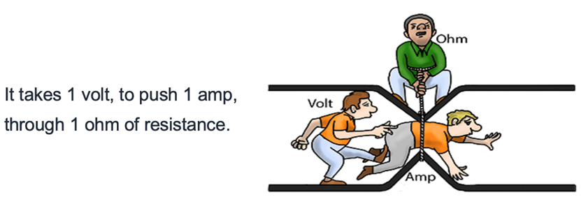
When 1 volt produces 1 ampere of current in an object, the resistance is 1 ohm (symbol is omega).

An ohm is a very small unit of resistance; a conductor might have a resistance of one or two ohms, whereas insulators have ohm measurements in the billions. All materials except superconductors have some resistance; conductors have low resistance, while insulators have high resistance levels.
The resistance in a wire increases as:
- The length of the wire increases.
- The thickness of the wire decreases.
- The temperature increases.
Self-directed Learning
Write answers to these questions without referring to your notes or copying information from another source. They are designed to test your understanding of the three concepts – voltage, current and resistance. Bring your ideas to the face-to-face session to discuss with your tutor and classmates.
- Describe what “electricity” is, in your own words.
- Explain what the electrical terms voltage, current and resistance mean in your own words.
- Voltage is also known by another name: electromotive force or EMF. What this other name for voltage means.
- Is it possible to have a condition where an electrical voltage exists, but no electric current exists? Or the opposite - where an electric current exists without an accompanying voltage? Explain your answers.
- What could you do to a closed circuit consisting of a battery, light bulb and a switch that would increase the amount of current? Explain your answer.
- Describe what you could do to the wire used in a circuit to decrease the amount of resistance presented by the wire.
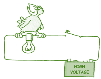
- If the switch is closed, what will happen to the bird? Explain your answer.

What we're covering:
- conventional flow and electron flow
- dry cell batteries
One of the confusing ideas when you are starting out as an electrical engineer is conventional current direction.

Conventional Current is explained in both the following videos.
Conventional Current VS Electron Flow - GCSE Physics
What is Electricity? Part 3: Which Way Do Electrons Flow?
Exercise 7

- Label the directions of both electron flow and conventional flow in this simple circuit.
- How do we define Conventional flow?
- How do we define Electron flow?
- Write an explanation, (using your own words), describing the two completely opposite systems for labelling the direction of electric current. (What historical events led to this confusion, and why does it still exist today? Which system should we use?)
Put your answers in the forum. (Take a screenshot of the image and load it onto a word document so that you can label it easily)
Dry Cell Batteries
Exercise 8
Prepare an A4 poster explaining how a battery works. Your poster should include:
- A fully labelled diagram of the cross-section of a battery.
- A brief explanation of the three main components of a battery – anode, cathode and electrolyte.
- Ordered steps explaining the process of generating electric power with a battery.
- What happens when a battery becomes ‘flat’?
Present your poster in the class forum.
Self-directed Learning
- Construct your own lemon battery. (Talk to your tutor about the components you will need for this.)
- Using a multimeter, measure the voltage of your lemon battery in volts (V).
- Using a multimeter, measure the current your lemon battery produces in amps (A).
- Using the following equation, calculate the Power output of your lemon battery (in watts, W). voltage x current = power
- A cell phone uses about 1.5 W when in talk mode. How many lemon batteries would we need to power a cell phone?
- A laptop uses around 25 W when in use. How many lemon batteries would we need to power that?
- The Chevy Volt batteries can supply 30,000 W. How many lemon batteries would be needed to deliver that power?

What we're covering:
- Ohm's law
- Ohm's law triangle
- Ohm's law practice
Ohm’s law describes the relationship between the three characteristics of the electrical circuit:
- The electron flow (current).
- The resistance to flow in the wire.
- The voltage.
Learn about the relationship between Voltage, Current and Resistance.
Georg Ohm found that, at a constant temperature, the electrical current flowing through a fixed linear resistance is directly proportional to the voltage applied across it, and also inversely proportional to the resistance. This relationship between the Voltage, Current and Resistance forms the basis of Ohm's Law and is shown below.
VOLTAGE = CURRENT x RESISTANCE
V = I × R
where:
V is the potential difference in volts, V.
I is the current in amperes (amps), A.
R is the resistance in ohms, Ω.
Sometimes it is easier to remember the Ohm’s Law relationships by using pictures:

So, with Ohm’s law, if you know two of the three quantities in the equation, you can figure out the value of the missing third one. For example, if you know the volts and the amps, you can use the equation to calculate the value of the resistance flowing through the circuit.
To use the triangle, cover up the missing (unknown) value and you will be left with the simple equation needed to calculate this missing quantity, i.e.

This video explains how to use the triangle if you’re confused.
Example 1 - 3A flows through a 240 V lamp. What is the resistance of the lamp?

R is the value that you are trying to find.
R = 240 ÷ 3
R = 80 Ω
Example 2 - what voltage is applied to a 20 ohm fixed resistor if the current through the resistor is 1.5 amps?

V is the value you are trying to find.
V = 1.5 x 20
V = 30 V
Ohm’s Law is used often so it is important you understand and remember it!
Exercise 9
Use the Ohm’s Law Triangle to calculate the following. Bring your workings to your next class and ask your tutor to check them.
Note: you must work in Ω, V and A for your calculations, so you need to convert some units before starting.
- A fan with resistance of 20 Ω is connected to a power supply. The current flowing through the circuit is 2.5A. What is the voltage of the power supply?
- A resistance of 30 Ω is placed in a circuit with a 90-volt battery. What current flows in the circuit?
- A motor with a resistance of 32 Ω is connected to a voltage source. Four amps of current flows in the circuit. What is the voltage of the source?
- The resistance of an electric stove burner element is 11 ohms. What current flows through this element when it runs off a 220 volt line?
- Determine the current flowing through a car's starter, whose resistance is 60mΩ at 12 V.
- The resistance of a handset is 4000 Ω, Calculate the voltage if the current is 2.5 mA.
- Calculate the resistance value of an electrical conductor if it is connected to a voltage of 12 V and an electric current of 0.3 A passes through it.
- An iron is connected to a 230 V power supply with a current of 5000 mA. Calculate the electrical resistance of the iron.
- What voltage is applied to a 20 ohm fixed resistor if the current through the resistor is 1.5 amps?
- What is the resistance of a lamp connected to a 110 voltage source that draws 2 amps of current?
Self-directed Learning
Watch the Ohm’s Law Experiment before making a graph of your own.
A student has a resistor of unknown resistance. She places the resistor in series with a power source of variable potential difference. Using an ammeter, she measures the current through the resistor and voltage across the resistor.

Her results look like this:
| Current (A) | 0.22 | 0.47 | 0.85 | 1.05 | 1.50 | 1.80 | 2.00 | 2.51 |
| Voltage (V) | 0.66 | 1.42 | 2.54 | 3.16 | 4.51 | 5.41 | 5.99 | 7.49 |
Plot these figures on the graph after downloading this worksheet.
What mathematical relationship do you see between voltage and current in this simple circuit? How could you calculate resistance from the graph?

What we're covering:
- watts
- prefixes
- electrical power rating
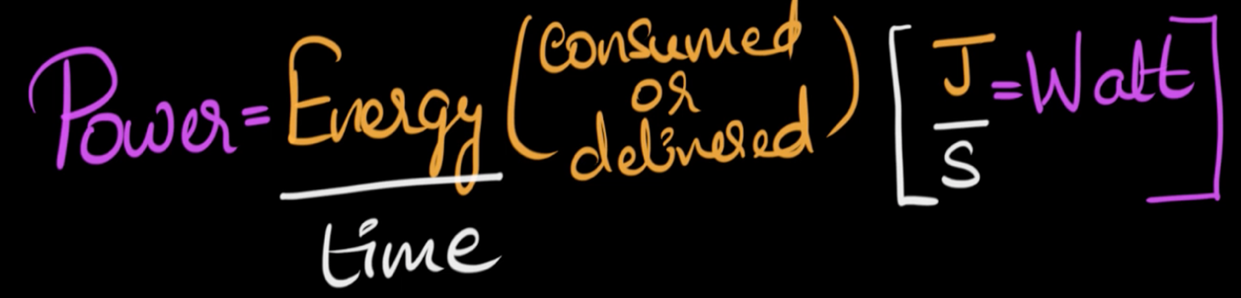
Electrical power is a measure of how much electric energy is converted to another form of energy (such as motion, heat, or light) over a set amount of time.
The watt is the SI unit of power and is equivalent to one joule per second.
The watt is also defined as the rate at which work is done when a current of one ampere, flows through a network with an electrical potential difference of one volt.
Watch the following videos discussing Electric Power.
Power can be calculated by multiplying current (I) by voltage (V).
POWER = CURRENT x VOLTAGE
Where:
- P is the power in watts (W)
- I is the current in amperes (A)
- V is the potential difference in volts (V)
The three quantities can be written into the Power Triangle, giving us three different combinations to find the various individual quantities:

Note - If the calculated power is a positive value, then the component is consuming or using power, but if the calculated power is negative, the component is generating power, such as a battery or generator.
It’s very common to see "watts" preceded by one of the standard SI metric prefixes: microwatts (µW), milliwatt (mW), kilowatt (kW), megawatt (MW), and gigawatt (GW) are all common depending on the situation. Ensure you adjust any calculations where the units are not in the standard units (W, V and A).
| Prefix Name | Prefix Abbreviation | Weight |
|---|---|---|
| Nanowatt | nW | 10-9 |
| Microwatt | µW | 10-6 |
| Milliwatt | mW | 10-3 |
| Watt | W | 100 |
| Kilowatt | kW | 103 |
| Megawatt | MW | 106 |
| Gigawatt | GW | 109 |
Exercise 10
Complete the questions below and then email or message your tutor for the answers.
- Calculate the power of a bulb that consumes 25 A of current when it is connected to a 12 V battery.
- What is the current when a 60 W lamp is connected to 120 V?
- What is the power when a voltage of 120 V drives a 2 A current through a device?
- A microwave oven transfers 4000 Joules of energy in 5 seconds. Calculate the microwave oven’s power, stating the unit of power.
- How much current does a 100 W lamp draw when connected to 120 V?
- Calculate the power of torch bulb rated at 2.5V and 500 mA.
- Calculate the voltage when part of an electric circuit consumes energy at 6 W while drawing a current of 3 A.
- An electric motor draws 150 amperes of current while operating at 240 volts. What is the power rating of this motor?
Electrical Power Rating
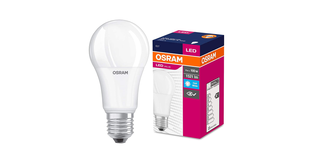
Electrical devices convert one form of power into another. For instance, an electrical motor will convert electrical energy into a mechanical force, while an electrical generator converts mechanical force into electrical energy. Conventional light bulbs first convert electrical energy into heat, and then into light, whereas LEDs (Light Emitting Diodes) convert electrical energy directly into light.
Electrical components are given a “power rating” in watts which indicates the maximum rate at which the component converts the electrical power into other forms of energy.
For example, a ¼ W resistor, a 100W light bulb etc.
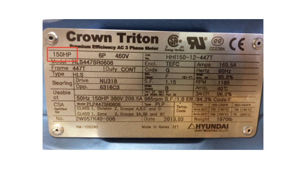
Some electrical devices such as electric motors have a power rating in the old measurement of “Horsepower” or HP. The relationship between horsepower and watts is given as: 1HP = 746W.
The higher power value or rating of a component, the more electrical power it will consume. It is important to understand the difference between a kW and a kWh.
What's the difference between kW and kWh?
It's easy to get kilowatt (kW) and kilowatt-hours (kWh) mixed up when talking about energy consumption. The main difference is in what they measure. To put it simply, a kilowatt is a measure of power and a kilowatt-hour is a measure of energy; power is the rate at which something uses energy, and energy (power x time) is the capacity to do the work.

Exercise 11
Complete the exercises below then email or message your tutor for the answers.
- A 750 W hairdryer is used for 15 minutes.
- Calculate the kWh used.
- Calculate the cost to use the hairdryer for 15 minutes every day for 1 year @ $0.28/kWh.
- A 615 W refrigerator runs 24h/day.
- Calculate the cost to run it for one week.
- Calculate the cost to run it for one year. (@ $0.28/kWh.)
- A current of 11 A at 240 V flows through an electric range. If it is used an average of 1 hour/day, calculate the:
- Watts used by the range.
- kWh used per month (30 days).
- Cost to run the range for one year at weekday peak rate (@ $0.37/kWh.)
- Calculate the kW rating of an electrical motor rated at 7.5 HP. Show your working and round your answer to 2 decimal places. (Recall 1 HP = 746 kW)
- The following table shows the average electrical consumption of several home appliances. Use the information in the table, to calculate the number of kW hours used and the cost of electricity used. (Assume the unit cost of electricity is $0.28.) Round all numbers to 3 decimal places. You can write your ideas on a piece of paper.
| Appliance | Hours Used | Energy (kW hours) | Cost ($) |
|---|---|---|---|
| 7 kW heat pump | 3 | ||
| 6 kW electric stove | 1 | ||
| 9 x 14W LED lamps (total 126W) | 6 | ||
| 90W television | 3 | ||
| TOTAL |
Self-directed Learning
Not all calculations give you a tidy answer. For example:
Calculate the current drawn by an electric dryer that consumes 6.0 x 10⁶ joules of energy when operating at 220V for 30 minutes.
Since 1W = 1J/s, the total power P=
= (6.0 x 106) J x (30 x 60) s
= 1.08 x 10¹⁰ W
Using I = P÷V
I = 1.08 x 10¹⁰ ÷ 220
I = 4.9 x 10⁷ A (rounded to 2 decimal places)
Your tutor will direct you to these modules at Pathways Awarua to practice your rounding skills.
- N5100 - Approximation and rounding.
- SN5100 - Approximation and rounding.
- TN5100 - Approximation and rounding.