| Day One | Day Two | Day Three | Day Four | |
|---|---|---|---|---|
| Course content | Relationship between power and energy Ohm’s Law Pie Chart |
Power & Energy | Circuit Diagrams | Series and Parallel |
| Self-directed learning | Power Calculations | Cost-effectiveness of using LED bulbs | Virtual Lab exercise - Series & Parallel | Virtual Lab exercise - Series & Parallel |
In order for you to gain the most value from your qualification and to prepare you for your assessment and the industry, make sure you complete all of the online and SDL tasks.

What we're covering:
- steps to follow
- practice exercises
So far, we have discussed relationships between voltages, current, resistance, and power. The Ohm's Law Pie Chart shows a summary of the relationships between these measurable quantities.
Which equation you use depends on what values you are given, or you measure. For example, if you are asked to find the power and you know the values for current and resistance, choose P = I2R.
Here are four steps to follow when using Ohm’s Law Pie Chart.
- Determine what variable you need to solve for: power (P), resistance (R), amps (I), or volts (V).
- Determine what variables you already know: power (P), resistance (R), amps (I), and volts (V).
- Find the formula in which you can plug your two values.
- Solve the equation.
All the possible combinations may seem overwhelming, but don’t forget that they all are combinations of just two equations, Ohm’s Law (V = IR) and Power (P = IV).
For instance:
Given the power formula: P = V x I and Ohm's law: V = I x R
The power formula could be rewritten as P = (I x R) x I by substituting Ohm's law in for the voltage. This simplifies to P = I2R
Alternatively the power formula can be writen as P = Vx V/R by substituting Ohm's law in for current. This simplifies to P = V2/R
Points to note:
- Since all of these terms are people’s names, we always use capital letters.
- Make sure to use compatible units when solving the formula. Convert any measurements with prefixes (like mA, KΩ, μV etc) to the base unit of A, Ω, V and W before calculating the answer, otherwise, you’ll get a result that is much bigger or smaller than you expected.
- These two formulae V √Px R and I= √P/R will be both need brackets inserted.
They should be entered on your calculator as √(P x R) and √(P ÷ R)
Watch
To learn more about where the Power formulae come from watch this set of videos:
Exercise 12
Fill in the blank cells on the following table by selecting the correct formula from the Ohm’s Law pie chart. (Download the worksheet here - answers to be provided at the end of this learning week)
| Known Values | Resistance R Ω |
Current I (A) |
Voltage V (V) |
Power P (W) |
|---|---|---|---|---|
| Current & Resistance | X | X | ||
| Voltage & Current | X | X | ||
| Power & Current | X | X | ||
| Volate & Resistance | X | X | ||
| Power & Resistance | X | X | ||
| Voltage & Power | X | X |
The video explains how to go about doing the different calculations.
Exercise 13
Use the pie chart to help you find the correct formula to answer these questions. In some cases, you will need to do use more than one formula to reach the final answer.
Self-directed Learning
Complete the worksheet and bring it to your next class for your tutor to check.

What we're covering:
- what 'power' and 'energy' are
- practice exercises
- Raise your right arm above your head slowly. Great – you just consumed about 4 Joules of energy
- Now raise your left arm above your head, but this time do so twice as fast as the first time.
- ou have just consumed about the same amount of energy as the first time, but you applied twice as much power since you raised your arm twice as fast.
Energy is the capacity of doing work and power is the time rate of doing work (or delivering energy). To get the same job done repetitively requires the same amount of energy each time, but by applying more power you can get the job done faster.
In physics, energy is defined as the amount of work that can be performed by force, whereas power is defined as the rate or pace of doing work.
The picture represents how energy and power differ. Both the mug and the bottle have water and a flowrate.
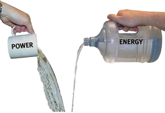
The mug, labelled ‘Power’, has a smaller amount of water, being poured at a greater rate, whereas the bottle labelled ‘Energy’ contains more water, being poured at a slower rate. The mug delivers more water in a given amount of time, but the total amount of water delivered is less than the bottle. The mug has higher power, but lower energy. The bottle releases smaller amounts of liquid for a longer period of time. It has a smaller power output but more energy. The mug releases all its water (energy) very quickly whereas the bottle holds much more water (energy), even if it is not losing it quickly.
Energy comes into our lives in many forms. Since energy ‘cannot be created nor destroyed’ we rely on various devices to convert one form of energy into another. We consume electricity by converting electrical energy to other forms of energy.Energy generated can be stored whereas power cannot. Power also cannot be converted or transformed.
Energy is usually measured in Joules. Power is measured in Watts, which is Joules per second.
You will commonly see power described in Watts and energy in “Watt-hours”. As you apply power (Watts) over a time duration (hours), you will figure out how much energy is consumed in Watt-hours.
It is common for people to use the words “power” and “energy” interchangeably. But you should now know the difference: energy is the total amount of work done, and power is how fast you can do it.
Watch
Take a look at the ‘Slide Energy’
Exercise 14
Work out the answers to questions 1 and 2 below on a piece of paper.
- Two students are lifting weights in the gym. Wiremu lifts the 40 kg barbell over his head 10 times in one minute; Ben lifts the 40 kg barbell over his head 10 times in 10 seconds.
- a.Which student does the most work? (Explain your answer.)
- b.Which student delivers the most power? (Explain your answer.)
- Your household's monthly electric bill is often expressed in kilowatt-hours. One kWh is the amount of energy delivered by the flow of l kW of electricity for one hour. Use conversion factors to show how many joules of energy you get when you buy 1 kWh of electricity.
- Drag and drop the statements that match each quantity.
- Answer the following questions.
Self-directed Learning
In this exercise you are to calculate the cost effectiveness of using a LED bulb in place of an incandescent bulb for one year.
A 100-W incandescent light bulb is typically replaced by a 20-W LED bulb. (They provide the same amount of light output.) Assume the bulb is turned on for 3 hours per day and the average energy rate charged by the power company is 20.1c /kWh.
Strategy:
- Calculate the energy used during the year for each bulb using Energy = P x t
- Multiply the energy used by the cost charged by the power company.
- Comment on which bulb is the cheapest for the year.
A 100-W incandescent light bulb costs about $1.50 and has a lifespan of around 1200 hours. A 20-W LED light bulb costs about $22 and has a lifespan of around 50,000 hours.
- How long would you expect each light bulb to last if it is turned on for 3 hours per day?
- How would this information about cost and lifespan affect your choice of light bulb?

What we're covering:
- electric circuits
- circuit symbols
- practice exercises
An electric circuit is a closed-loop network which provides a return path for the flow of electrons. The electric current flows from the source (such as a battery), through the conducting material (e.g., wires and cables), to the load (i.e., light bulb, resistor, diode etc.) before returning back to the source.
Electric circuits can be described in a variety of ways:
1. Using words – e.g. "A light bulb is connected to a D-cell".
2. Drawing – e.g.,

3. A circuit diagram - where conventional circuit symbols are used to provide a schematic diagram of the circuit and its components.

Some commonly used circuit symbols are shown below.

There are around 1750 circuit symbols altogether – this is only a very small sample above!
Note
Some countries use alternative symbols for the same component.
Notice the long line of the cell, or battery, represents the positive terminal and the short line represents the negative terminal.

A straight line is used to represent a connecting wire between any two components of the circuit.
Any electrical device that offers resistance to the flow of charge is referred to as a resistor and can be given this symbol.
A simple circuit comprises the following:
- A power source, including cells and batteries.
- A load or resistor.
- Conductors or wires, connecting the circuit components to the power source to ensure a continuous pathway for current to flow.
- A switch to open or close the circuit.
Exercise 15
Use circuit symbols to construct schematic diagrams on a piece of paper for the following circuits:
- A single cell, light bulb and switch are placed together in a circuit such that the switch can be opened and closed to turn the light bulb on.
- A three-pack of D-cells is placed in a circuit to power a flashlight bulb.
- The diagram below

- The diagram below

Work through a selection of questions from this Simple Circuits Worksheet. Scroll to the end of the worksheet to find answers/useful notes about each question.
Self-directed Learning
Visit this site and practice building circuits in the virtual lab.
Once you feel confident using the tool, construct the following circuits according to the instructions provided. Fill in the table in this worksheet once you complete each circuit. (Don’t leave it until the end!). When you have completed all six circuits, summarize your findings.

What we're covering:
- series and parallel combinations
- series and parallel circuits
When there are two or more components in an electrical circuit there are a couple of basic ways, we can connect them. They can either be connected in series or in parallel combinations.
A series connection is a connection in which the components of the circuit (resistors) are wired to one another in a single path. The current is the same through each resistor but the voltage around each resistor is not and can be found using Ohm’s Law for that part of the circuit.
A circuit is in parallel when the electric current has multiple paths to flow through. The components that are a part of the parallel circuits will have a constant voltage across all ends. The voltage across each resistor is the same but the current is not and can be found using Ohm’s Law.

The major difference between the two circuits is the amount of current that flows through each of the components in the circuit. In a series circuit, the same amount of current flows through all the components placed in it. On the other hand, in parallel circuits, the current flowing from the source will be split as it flows through each of these components.
For each circuit below, which two devices are connected in series and which two devices are connected in parallel? Note your answers on a piece of paper and check with your tutor next time you are on campus.

Compare electron flow to the flow of cars along a toll way system.

Read
Read the explanation of the Tollbooth Analogy which compares current flow in a circuit to the flow of cars along a toll way system.You can see that adding resistors in series is quite different to adding them in parallel. Adding more resistors in series means that there is more overall resistance; yet adding more resistors in parallel means that there is actually less overall resistance.
| Series | Prallel |
|---|---|
| In an electrical circuit, componens are arranged in line. | In an electrical circuit, components are arranged parallel to each other. |
 |
 |
 |
![[ADD IMAGE'S ALT TEXT]](/sites/default/files/design-team/NZMA3001A/6408/ParallelCircuit.svg) |
| If one component breaks down, the whole circuit will burn out (e.g. a string of Christmas lights). | Other components function even if one component breaks down, each has its own independent circuit ( e.g. power outlets in a house). |
| The current is the same throughout a series circuit. The same amount of current flows through all the components. |
The current flow splits into different paths. The total circuit current equals the sum of the individual branch currents. |
| Voltage across the circuit equals the sum of voltages across each device. Each resistor uses a portion of the total voltage supplied by the battery. |
Voltage in each parallel branch is the same as V source. |
| Adding resistance increases total R. When resistors are put in a series of circuit, the voltage across each resistor is different even though the current flow is the same through all of them. |
The total resistance of a parallel circuit is less than any of the individual branch resistances. Adding resistance reduces total R. |
The equations may be summarised as follows:

Numeracy Check
Calculating total resistance for a parallel can be tricky. Take this circuit for example:

The total resistance of the circuit is given by:

On your calculator press (1/15) + (1/7) = to give you 0.2095238…
and now without clearing your screen, press the reciprocal button
(1/x or x-1) to give you total resistance (R) of 4.77 Ω (2 dec. places)
Now try finding total resistance for this circuit, following the steps above.
You should get 2.14 ohms (correct to 2 decimal places).
Read
Read the information about Series and Parallel Circuits then answer the questions at the end of each lesson.
You may find these questions very challenging! Answers and explanations are provided to assist you but see how far you can get on your own before clicking on them.
Self-directed Learning
Continue on from the SDL in Lesson 11 (Complete the virtual lab exercise and answer the questions. Summarise what has happened in each case in terms of current and voltage.)
This week's worksheet answers.