| Day One | Day Two | Day Three | Day Four | |
|---|---|---|---|---|
| Course Content | Connecting instruments to measure V, R, I & P. | Cheat Sheet DC Electricity. | Magnets, magnetic fields, and magnetic terms. | Electromagnets used in the electrical industry. |
| Self-directed Learning | Virtual Lab exercise – connecting an ammeter. | Virtual Lab exercise – connecting a voltmeter. | Footprints-science Magnets activities. | Electromagnetic doors. |
In order for you to gain the most value from your qualification and to prepare you for your assessment and the industry, make sure you complete all of the online and SDL tasks.
What we're covering:
- Course 1 recap
- Measuring voltage
- Measuring current
- Measuring resistance
- Measuring wattage and power consumption
- Practice exercises
Recall from Course One, current can be measured using an ammeter, potential difference (voltage) between two points can be measured using a voltmeter and an ohmmeter can be used to measure resistance.

The multimeter is the most important electronic test instrument since it can measure all three of these quantities. There are two types of multimeter - analogue and digital, both having their own advantages. What advantage does the multimeter have over the three meters mentioned above?
Drag and drop each advantage into the correct column.
Exercise 16
Read the information here if you are still a little unsure about using a multimeter.
Connecting instruments in a circuit
Measuring Voltage
A multimeter (or voltmeter) must be connected in parallel with whatever device it is measuring. This is necessary because objects in parallel experience the same potential difference.
The voltmeter calculates the difference in voltage between the two different points (i.e., on different sides of the resistor).
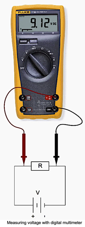
Since voltmeters are connected in parallel, they must have a very large resistance so that they don’t attract any current.
Measuring Current
To measure the current through a device or component, the ammeter (or multimeter) is placed in series with the device or component. A series connection is used because objects in series have the same current passing through them.
When an ammeter is used to measure the current through two resistors connected in series to a battery, a single ammeter is placed in series with the two resistors because the current is the same through both resistors.
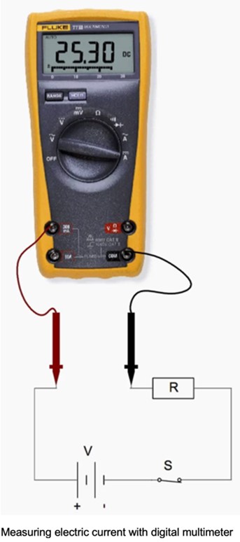
Ammeters must have a very low resistance. If the resistance is not negligible, placing the ammeter in the circuit would change the equivalent resistance of the circuit and modify the current that is being measured.
Measuring Resistance
Note - You can measure the voltage and the current of a live circuit and use those figures to calculate the resistance (using Ohm's Law), but you can't actually measure the resistance of a live circuit. Power should be disconnected before connecting the ohmmeter.
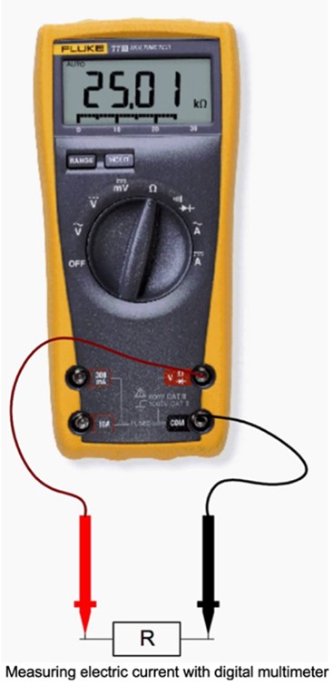
Place a probe tip at each end of the component being measured to measure resistance. Since resistance doesn’t change with the direction of current flow, the positive probe and the negative probe can be on either end of the circuit to get an accurate resistance reading.
Measuring Wattage and the Power Consumption
Watts = Voltage x Current
So, to measure the power in watts of a load or appliance, both the voltage across the load and the current passing through it must be measured. If you have two multimeters, you can measure the voltage and current simultaneously.
Be aware that when any quantity is measured, the measuring device has an influence on the measurement. The resistance of the meter will reduce the current slightly, giving a lower reading than the actual value with the meter not connected.
Exercise 17
For questions 1, 2, 7 and 8, write your answers on a piece of paper. Email your tutor, or take your answers to class to get them checked.
- What do you think might happen if you placed a voltmeter in series with a component to be tested?
- Why shouldn’t you connect an ammeter in parallel with a component?
- Drag and drop the correct words about voltmeters and ammeters.
4. to 6. Complete the following activities about circuits.
7. Most ammeters contain fuses inside to provide protection for both the person using the ammeter, and the instrument. Voltmeters generally do not contain fuses inside, because they are unnecessary. Explain why ammeters use fuses and voltmeters do not.
8. In the circuit shown, the resistances of the resistors are R1 = 100 ohms and R2 = 150 ohms. The supplied voltage is 120V.

- If you connect an ammeter at 1, what current (in Amperes) will the ammeter read?
- If you connect an ammeter at 2, what current (in Amperes) will the ammeter read?
- If you connect a voltmeter at 3, what voltage (in Volts) will the voltmeter read?
- If you connect a voltmeter at 4, what voltage (in Volts) will the voltmeter read?
Self-directed Learning
Visit the Virtual Lab site again and build the circuits according to the instructions provided. Refer to today’s lesson about how to connect ammeters in a circuit.
Connecting an Ammeter
Ammeters are wired “in series” with the light bulb in a circuit. Be sure to connect the ammeter so that current enters (one of) the + / red terminals and exits the –/black terminal to the rest of the circuit.
Build the circuit shown. The ammeter will be placed in the circuit at 3 different points: A, B and C.

To measure the current at point A, connect the ammeter "in series" with the light bulb as shown. Measure IA, (currently leaving the battery and entering the ammeter). Repeat at points B and C.
IA =
IB =
IC =

Take and record current measurements for the circuit series at the lettered points.
IA =
IB =
IC =
How are IA, IB, and IC related in this circuit?

- How is the brightness of the bulb related to the current flowing?
- What can you say about the current flowing through each bulb in a series circuit?
- Measure and record the current for the parallel circuit shown at 3 different points: A, B and C. Connecting the ammeter at points B and C can be confusing so double-check you have done this correctly.
IA =
IB =
IC =
- How does the current through the two bulbs in the parallel circuit compare?
- What is the mathematical relationship between Ia, Ib, and Ic?
- Explain what is happening to the current as it travels around this circuit.
- If a bulb is not glowing, does that mean there must necessarily be no current flowing? Explain.
- Does the mathematical relationship between Ia, Ib, and Ic that you suggested above, still work for this circuit?

What we're covering:
- DC cheat sheet
Before we move on to the next section about magnetism let’s recap what we have learnt about DC electricity.
Exercise 18
In this exercise you will create a ‘Cheat Sheet’ about DC Electricity and email the final document to your tutor.
A cheat sheet is NOT for cheating! Cheat sheets are a very valuable way to organise information - concentrating everything you need to know about a particular topic onto the front and back of one A4 piece of paper.
You should not put everything onto your cheat sheet – just the most important things:
- Important information from notes, classwork, extra reading, videos etc.
- Important symbols and formulae.
- Key terms and definitions.
- Key steps to solve a problem.
- Key diagrams or infographics.
- Important theories.
Look at examples of cheat sheets online. You will notice a variety of techniques are used to make the cheat sheet easy to navigate – font size and style, diagrams, columns and boxes to separate information, colour-coding text etc. Then have fun creating your cheat sheet.
HINT - The key areas to focus on are:
- Voltage
- Current
- Resistance
- Power
- Energy (Work Done)
- Series Circuits and Parallel Circuits
- Circuit Diagrams
- Ohm’s Law (and the relationships between the different variables)
Self-directed Learning
Visit the Virtual Lab site again and build the circuits according to the instructions provided. Refer to your notes about connecting voltmeters in a circuit.
Begin with the simple one-bulb circuit again. With the switch closed, measure and record the voltage drop VBC across the light bulb as shown. Also measure:
- VAB (voltage drop along the wire from +ve battery terminal to the light bulb)
- VCD (bulb back to -ve terminal of battery)
- VDA and VAD (reversing the red and black leads)

Now repeat all the measurements – this time with the switch open. List all your measurements (switch closed and open) the table: you can create one in a word document.
| Reading | Switch closed | Switch open |
|---|---|---|
| VBC | ||
| VAB | ||
| VCD | ||
| VDA | ||
| VAD |
- How are VDA and VAD related?
- How does VAB + VBC + VCD compare to VAD?
- What do you get if you sum up the voltage drops once around the circuit? (i.e., VAB + VBC + VCD + VDA)
- With the switch closed does it appear reasonable to ignore the voltage drops VAB and VCD along the wire segments?
For the series circuit shown, measure the voltage drops across each light bulb and the battery again. Measure VAB, VBC and VCA around the circuit with the switch closed. What is the sum of the voltage drops around the circuit?

For the parallel circuit shown, measure the voltage drop across each bulb and the voltage drop across the battery and record. How do the voltage drops compare?

Make voltage drop measurements across all bulbs for the combined circuit VAB, VBD, VCD and VDA.

From your observations and measurements of voltages in the combined circuit (the final circuit) answer the following questions:
- Find the sum of the voltage drops along path A-B-D (VAB + VBD). Compare this sum to the voltage supplied by the battery, VAD.
- Find the sum of the voltage drops along path A-B-C-D (VAB + VCD). Compare this sum to the voltage supplied by the battery, VAD.
- Research Kirchhoff's Loop rule. How does this relate to the combined circuit above?

What we're covering:
- Types of magnets
- Magnetic fields
- Magnetic force
- Earth's magnetic field
Let’s start off by watching these two videos about magnets.
The videos cover these important concepts:
- Properties of a magnet
- Types of magnets
- Magnetic fields
- Magnetic field lines
- Magnetic force
- Earth’s magnetic field.
Magnets are objects that can produce a magnetic field. Magnets can attract or repel other materials such as iron, cobalt and nickel. All magnets have a north pole and a south pole. Opposite poles attract each other, like poles repel each other. Objects that can be magnetised are termed Ferromagnetic (iron, nickel, cobalt).
There are three types of magnets:
- Permanent magnet
- Temporary magnet
- Electromagnets
Permanent magnets
- Magnetised materials with magnetism already built into them.
- Magnetism is not easily destroyed.
- Capable of holding a permanent magnetic field and cannot be turned on and off.
- Made from alloys (ferrite, alnico, samarium cobalt and NIB) and naturally occurring minerals such as lodestone.
- May be created by exposing the magnetic material to a very strong external magnetic field.
- Can be split into two or more magnets, each with N and S poles which cannot be isolated.
- Used in DC motors, cars, generators, headphones, speakers, sensors, fridge magnets and information storage such as swipe cards and hard drives.

Temporary magnets
- Require an applied magnetising force to induce a magnetic field. When the magnetising force is removed, these materials lose their magnetic property.
- Cannot remain magnetised on their own.
- Usually made of "soft" magnetic materials (transformer steel, silicon steel and soft iron) that are easy to magnetise and de-magnetise.
- Useful in transformers, lifting magnets, bells, contactors, relays, solenoids, and locking magnets where the holding force ceases when the current is turned off.

Electromagnets
Electromagnets are temporary magnets consisting of a coil of wire wrapped around an iron core. When an electrical current is introduced, a magnetic field forms around the coil. (We will study electromagnets later in this course.)
Magnetic Fields
As you know magnets have two poles and depending on the orientation of two magnets there can be attraction (opposite poles) or repulsion (similar poles). You will also be aware of a region extending around a magnet where this attraction or repulsion occurs. The magnetic field describes this region. The magnetic field illustrates how the magnetic force is distributed in the space around and within something magnetic. It depicts how a moving charge flows around a magnetic object.
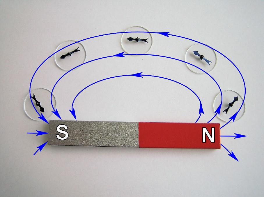
Magnetic fields cannot be seen however their presence can be detected by placing a compass at different points around a bar magnet. Field lines can be drawn by marking the direction of the compass needle at these points.
Another method of detecting a magnetic field is with iron filings. The iron filings align themselves along the magnetic field in lines, defining the shape (but not direction) of the magnetic field.

Note - these (imaginary) magnetic field lines:
- Never cross.
- Are drawn leaving the north pole of the magnet entering the south pole.
- Do not start or stop anywhere, they always make closed loops and will continue inside a magnetic material.
- Are most dense at the poles. (The closer the lines are to each other, the stronger the field.)

Exercise 19
Sketch the magnetic field lines inside and outside this bar magnet - use a piece of paper.

The measurement of the magnetic field involves measuring both its strength and direction. Measuring direction is straightforward – we use a magnetic compass which lines up with the field. Magnetic fields occur whenever charge is in motion. As more charge is put in more motion, the strength of a magnetic field increases. Strength is measured using a magnetometer.
Magnetic flux density (‘field strength’) has symbol B, unit tesla (T).
Magnetic field may also be defined as the magnetic flux density. Magnetic flux density is the amount of magnetic flux at a particular point. (Magnetic flux is the flow of magnetic energy symbol Φ, and units Webers, Wb). One tesla is equal to one Weber per square metre.
Magnetic Force
Magnetic force is a force that arises due to the interaction of magnetic fields. A magnet, magnetic material, or current- carrying wire must enter the magnetic field of an existing magnet for the force to occur. Magnetic Force can be either repulsive or attractive force. At least two magnets must be present to create a magnetic field - a single magnet cannot create a magnetic force.
Magnetic forces are measured in Newton. These videos help to explain the concept of magnetic force.
The Earth's Magnetic Field
Earth may be thought of as a giant magnet. The magnetic field arises from Earth’s molten metallic core and extends thousands of kilometres. The magnetic field protects us from the solar winds. These are currents of particles charged of energy emanated from the sun which emit radiation.
The poles of the Earth's magnetic field are not necessarily aligned to the geographic poles. Currently the magnetic south pole is located near the geographic north pole. This is why the north pole of a compass will point towards it (opposite poles attract).

The Earth’s magnetism can be imagined as a giant bar magnet tilted at an angle of 11 degrees to its axis and having two poles. The field lines go out of Earth near the South Pole, enter Earth in the North Pole, and are not aligned with the geographic poles. (The Geographic North Pole is where lines of longitudes converge into what we call the North Pole. The Magnetic Pole is a point in Northern Canada where the northern lines of attraction enter the Earth.)
The natural magnetism of the Earth is what makes a compass work.
Self-directed Learning
This site has lots of information, animations, activities and quizzes on all sorts of science topics. Take a look.
Today you should concentrate on the section about magnets. Four activities are provided here based on today’s lesson.

What we're covering:
- right hand (grip) rule
- what electromagnets are
- application of electromagnets
Charges in motion (an electrical current) produce a magnetic field.
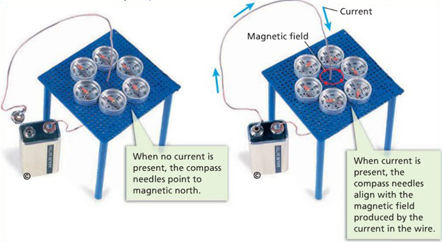
The magnetic field lines around the current-carrying wire are closed loops.

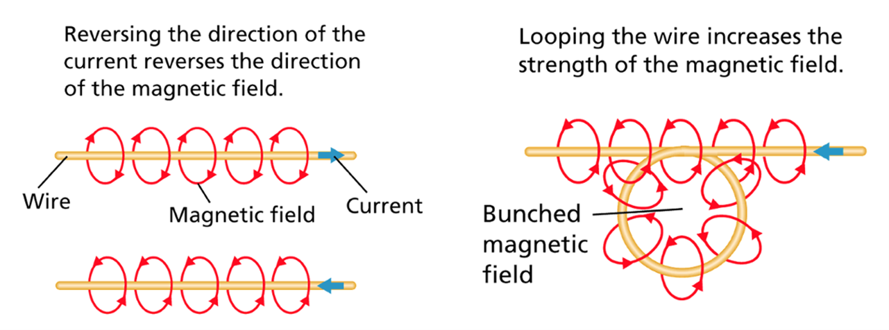
The magnetic field produced by a current has three distinct characteristics:
- It can be turned on or off.
- Its direction can be reversed.
- Its strength can be changed.
The Right Hand Grip Rule
We use the right-hand grip rule, to determine the direction of the magnetic field created by a current. To apply the rule, point your right thumb in the direction of the conventional current (positive to negative) and curl your fingers. Your fingers will be curled in the same direction as the magnetic field around the wire.

What is an Electromagnet?
Electromagnetism is the interaction between conductors and fixed magnetic fields.
When a coil of wire is supplied with an electric current, we call it a solenoid. (Notice the magnetic field around a solenoid resembles that of a bar magnet.)

‘An electromagnet is a type of magnet in which the magnetic field is produced by an electric current. Electromagnets usually consist of wire wound into a coil. A current through the wire creates a magnetic field which is concentrated in the hole, denoting the centre of the coil. The magnetic field disappears when the current is turned off. The wire helix is often wound around a magnetic core made from ferromagnetic material such as iron; the magnetic core concentrates the magnetic flux and makes a more powerful magnet.’(Wikipedia, 2022)
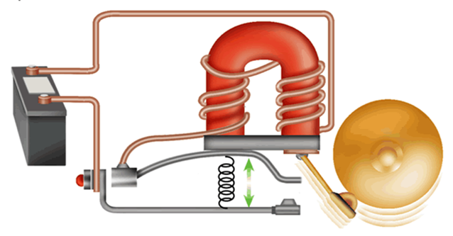
Mechanically, an electromagnet is quite simple. It consists of a length of conductive wire, usually copper, wound around a metal rod called a solenoid.
A current is introduced, from a battery or another source of electricity, and flows through the wire.
This creates a magnetic field around the coiled wire, magnetizing the metal as if it were a permanent magnet. The strength of the magnet is directly related to the number of times the wire coils around the rod and the material used for the core.

Electromagnets are temporary magnets - they produce magnetic fields only when electric current is flowing. They are useful because you can turn the magnet on and off by completing or interrupting the circuit, respectively.
Watch the animation of electromagnetic induction here.
A conductive wire, usually insulated copper, is wound around a metal rod. (The wire will get hot to the touch, which why insulation is important.)
The tighter the wire is wound around the rod, or core, the more loops the current makes around it, increasing the strength of the magnetic field. In addition to how tightly the wire is wound, the material used for the core can also control the strength of the magnet. For example, iron is a ferromagnetic metal meaning it is highly permeable.
Exercise 20
Find out what permeability means in relation to magnetism and write a definition in your own words. The post your definition in the class forum and compare your answer to those of your classmates.
Application of Electromagnets
Electromagnets are used in numerous electromechanical and electronic devices. The doorbell is a very simple example of how we use electromagnets in our day-to-day lives.
Learn how an electric bell works in this video and from this website.
Closed Circuit: Pressing the button closes the circuit of the doorbell. Closing the circuit turns on the electromagnet in the door.
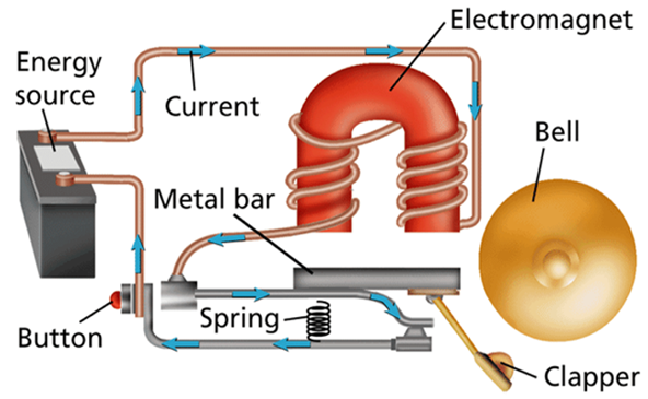
Open Circuit: The electromagnet attracts a metal bar, and the clapper strikes the bell. At the same time, the circuit opens, turning off the electromagnet. The spring returns to its resting position.
Electromagnets are also found in the large cranes used in waste yards. A switch is turned on in the crane producing a current in the electromagnet which can then lift, move and drop heavy iron or steel objects.
Other common uses for electromagnets include:
- Generators, motors, and transformers.
- Headphones and loudspeakers.
- Relay switches and valves.
- Data storage devices like VCRs, tape recorders, hard discs, etc.
- Induction cooker.
- Magnetic locks.
- MRI machines.
- Mass spectrometers.
- Chargers (phones, electric cars etc.)
You may have heard of an electromagnet called the Large Hadron Collider? The LHC is a 27 km particle accelerator. All the magnets on the LHC are electromagnets. The main dipoles generate powerful 8.3 tesla magnetic fields – more than 100,000 times more powerful than the Earth’s magnetic field. The electromagnets use a current of 11,080 amperes to produce the field, and a superconducting coil allows the high currents to flow without losing any energy to electrical resistance. You can learn more about the LHC here.
Self-directed Learning
The diagram shows an electromagnet used in a door lock.

- When the button is pushed the door unlocks. Explain in detail why this happens.
- When the button is released the door locks. Again, explain in detail why this happens.
- Explain why electromagnetic doors are safe for use as emergency doors (i.e. would happen if the power went out?)
More activities from footprints-science can be found here and here.