| Day One | Day Two | Day Three | Day Four | |
|---|---|---|---|---|
| Course Content | Electromagnetic Induction - electric motors. | Electromagnetic Induction – generators. | Electromagnetic Induction - transformers. | Differences between AC and DC. Common AC terms |
| Self-directed Learning | Footprints-science Motors activities. | Generator questions. | Transformer questions. | Multichoice quiz |
In order for you to gain the most value from your qualification and to prepare you for your assessment and the industry, make sure you complete all of the online and SDL tasks.

What we're covering:
- Faraday's Law
- Motors, generators and transformers
We have already seen that charges in motion (an electrical current) produce a magnetic field. The inverse is also true: moving a bar magnet through a coil of wire will induce a current to flow through the wire.

This process of generating electric current with a changing magnetic field is known as electromagnetic induction, or Faraday’s Law. As long as the conductor is part of a closed circuit, current will flow through it whenever it crosses magnetic field lines. One way this can happen is pictured. (It shows a magnet moving inside a wire coil.) Another way is for the coil to move instead of the magnet.
According to Faraday the strength of the induced current may be increased by:
- Increasing the strength of field, or size, of the magnet.
- Increasing the speed of the motion.
- Changing the angle of the magnet (to be more perpendicular).
- Increasing the number or turns of coil.
In other words, a changing magnetic field produces an electric field, and a changing electric field produces a magnetic field.
Motors, Generators and Transformers
Look around your house and you will find that it is filled with electric motors. Since our homes use AC power, most of these gadgets have AC motors. DC motors are more likely to be found in things that use batteries.
Exercise 21
Starting in the kitchen, make a list on a piece of paper of all that gadgets that have motors in them:
- kitchen
- laundry
- bathroom
- bedroom
- car
- garage
- other places
Almost every household gadget that moves uses an electric motor to achieve that movement.
Motors
An electric motor is a device that uses an electromagnet to change electrical energy into mechanical energy. Read here “How Electric Motors Work”.
When a current carrying conductor or wire is placed in a magnetic field, electrical energy is transformed into mechanical energy.

In the example above, the single wire moves up or down, whereas a wire loop will move through a half turn.
The movement is due to the magnetic field of the magnets interfering with the magnetic field of the electric current flowing in the conductor. Since the loop has become a magnet, one side of it will be attracted to the north pole of the magnet and the other to the south pole.

The principle of the electric motor goes a step further so that, at the moment that this half turn of motion completes, the field of the electromagnet flips. You flip the magnetic field by changing the direction of the electrons flowing in the wire, which means flipping the battery over. The flip causes the electromagnet to complete another half turn of motion. If the field of the electromagnet were flipped at exactly the right moment at the end of each half turn of motion, the electric motor would spin continuously.

There are three basic parts in any motor: a stator, a commutator, and a rotor. Together they use electromagnetism to make the motor spin. As long as the motor receives steady current, the motor works.
- The stator stays stationary during the rotation. The outside of a motor is the stator: a permanent magnet or field magnet that does not move. Often the stator has a row of magnets and looks like a drum.
- The rotor or armature is the part of the motor that rotates. The rotor is the electromagnet of the system. It is inserted in the stator. The current is in opposite directions on each side of the armature causing one side to move up while the other side moves down.
- The split-ring commutator rotates with the armature. The commutator reverses the current between the rotor and the battery which keeps the axle spinning in a single direction. By reversing the magnet’s polarity, the rotor continues spinning through repulsion and attraction.
- Brushes that touch the commutator conduct current to the armature. The brushes do not move.

An electric motor consists of a DC power supply; a magnetic field; a current conducting coil; a rotor which rotates the coil; a commutator which reverses the direction of the current in the circuit; and brushes which conduct electricity between the moving coil and the circuit.

When current flows through the coil which is placed between the magnets, the coil experiences a torque*, and starts to rotate. When the coil completes a half-rotation, the DC current gets reversed, causing the torque in the opposite direction. This results in the coil to rotate further, completing the other half cycle in the same direction. The split rings are responsible for reversing the direction of the current in the circuit, after every half cycle.
*Torque is the measure of the force that can cause an object to rotate about an axis.
Self-directed Learning
Put these sentences about motors into the correct order.
More activities from footprints-science…

What we're covering:

- motors vs generators
- alternators and generators
A generator uses motion in a magnetic field to produce an electric current.
Compare - a motor converts electrical energy to mechanical energy, whereas generators do the opposite – they convert mechanical energy to electrical energy.
This video differentiates between the motor and the generator. (Begin watching at 25 seconds.)
In a generator, some form of energy is applied to turn a shaft. This causes a coil of wire to rotate between opposite poles of a magnet. Because the coil is rotating in a magnetic field, electric current is generated in the wire.

As you can see the structure of a simple generator is essentially the same as a motor. If you were to mechanically turn the shaft of a motor (instead of using electro-magnetism to turn it), the motor would generate electricity just like an electric generator.
Learn how to make a very simple electric generator in this video. Making your own generator will help you understand how a generator works.
Alternators and generators
The simplified difference between these two terms is - an alternator converts mechanical energy into alternating current (AC) electrical energy, whereas a generator converts mechanical energy into either alternating current (AC) or direct current (DC) electrical energy.
The generators in cars and most power plants produce alternating current.
Applications
In most power plant generators, a source of mechanical energy turns huge turbines. The turbine is attached to the armature of a generator, which produces electric current.
The energy to turn the turbine may come from burning fuel, falling water, or some other energy source. A hydroelectric power plant uses the kinetic energy of falling water to turn a turbine and generate electricity.

Watch this clip to see how falling water is used to generate electricity.
This video looks at the various ways power is generated.
Exercise 22
- Match the terms to its correct definition and parts.
- How is current induced in the armature (of a generator)? Make notes for your own records.
- How does an electric motor differ from a generator? Compare them using a Venn Diagram, choosing your answers from the box below. Download a copy of the worksheet to write your answers into.
Self-directed Learning
- Answer the questions about generators.
- Suggest four ways to increase the induced current above.
- The diagram illustrates how a steam turbine generator works. Write down what is happening at each stage 1-6.
- Why do we use water in generators?

What we're covering:
- transformers
- step up and step down transformers
- transformers and voltage
Another common electromagnet is the transformer. An electric transformer is a device that uses electromagnetic induction to change the voltage of electric current. A transformer may either increase or decrease voltage, but it only works with alternating current.
A transformer usually consists of two coils of wire wrapped around the same iron core. The primary coil (P) is the input coil of the transformer, and the secondary coil (S) is the output coil.

When alternating primary current Ip passes through coil P, it magnetises the iron core. Because the current is alternating, the magnetic field of the iron core keeps reversing. This changing magnetic field induces alternating current in coil S, which is part of another circuit.

'Play' with the transformer simulators at these sites. What happens to the input and output voltages as you change the number of windings of the coils?
Voltage can be changed depending on the number of loops in the primary and secondary coils. If the output voltage of a transformer is greater than the input voltage, it is called a step-up transformer. If the output voltage of a transformer is less than the input voltage it is called a step-down transformer.

Voltage is determined by the turns-ratio equation:
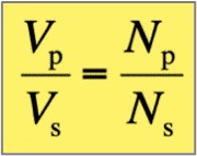
Vp is the input voltage of the primary coil
Vs is the output voltage of the secondary coil
NP is number of windings of the primary coil
NS is the number of windings in the secondary coil
The turn’s-ratio is the same as the voltage ratio.
In an ideal transformer the power in the primary coil is equal to the power in the secondary coil i.e.
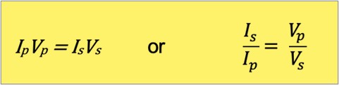
The current ratio is the inverse of the voltage ratio.
Transformers are extremely important because they efficiently change voltage and current, while providing the same total power.

Exercise 22
Answer the following questions about transformers.

Self-directed Learning
Answer the following questions about transformers based on today’s lesson.
- In your own words explain what a transformer does.
- What are the parts of a transformer?
- Where are transformers used?
- What do we call a transformer that increases voltage?
- What do we call a transformer that decreases voltage?
- Draw the following table on a piece of paper and match the numbers to the correct labels:
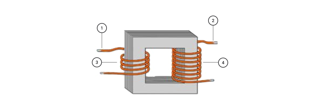
Term Output current Input current Primary coil Secondary coil Number - Draw the correct (circuit diagram) symbol for the step-up transformer:

- Explain how an electric transformer changes the voltage of an electric current.
- Why does a transformer only work with Alternating Current?

What we're covering:
- recap AC and DC
- Amplitude
- Alternation
- Cycle
- Instantaneous value
- Frequency
- Time period
- Waveform
- Peak to peak
- Wavelength
- Root mean square
In Course 2 you learnt a little bit about direct current (DC) and alternating current (AC). Re-read those notes to refresh your memory before continuing.
| Alternate Current | Direct Current | ||
|---|---|---|---|
| Meaning | Current reverses direction at equak time intervals | Current flows in one direction - it is direct - hence its name | |
 |
 |
||
| Abbreviation | A.C. | D.C. | |
 |
 |
||
| Change in Polarity | Change in polarity after a fixed interval. (It is not fixed.) | No change in polarity - it is fixed | |
| Frequency | Frequency depends on country (50Hz in NZ). | Frequency is zero | |
| Current | Varies with time. | Constant magnitude. | |
| Uses |
Power distribution: used to transmit current over long distances without losing power. High voltages are used for power transmission, and then reduced to safer levels for consumers, using a simple transformer - transformers do not work with direct current. High-Power Applications: in homes, factories, and other establishments. |
Batteries: both re-chargeable and non-rechargeable batteries can only store and supply DC. Low Power Electronics: radios, computers, mobile phones, use DC to power the electronic circuits. Equipment powered by AC but will convert AC to DC using a rectifier. Solar panels: produce DC directly from the solar panels themselves. |
|
Common AC Waveform Terms
Amplitude
Amplitude (A) is a measurement of the magnitude or intensity of an AC signal. The amplitude of an AC waveform is its height as depicted on a graph over time. An amplitude measurement can take the form of peak, peak-to-peak, average, or RMS quantity. Peak amplitude is the height of an AC waveform as measured from the zero mark to the highest positive or lowest negative point on a graph. The peaks of the waveform are identified and measured using an Oscilloscope.
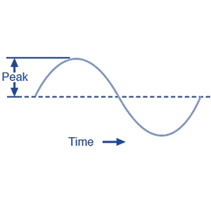 |
One way to way to express the amplitude of an AC quantity is to measure its peak height on a waveform graph. This is known as the peak (or crest) value of an AC wave form and usually shown as Vpk. |
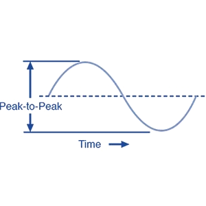 |
Another way to measure amplitude is to measure the total height between opposite peaks. This is known as the peak-to-peak value of an AC wave form and is usually shown as Vp-p. |
Alternation
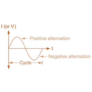 |
The positive and negative halves of the AC waveform are referred to as Alternations. Alternations are defined as a half-cycle since two alternations make up a cycle. |
Cycle
 |
A cycle is a single repetition of back and forth alternating current flow, in other words the complete transition through one positive alternation and one negative alternation. |
Instantaneous value
The magnitude of the waveform at any point of time is called instantaneous value.
The value of voltage or current at any given time quantity is designated by a lower-case letter (either a small e for emf or small v for voltage, and a small i for current).
Frequency
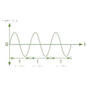
Frequency, (ƒ) is the number of times the waveform repeats itself within a one second time period, or the number of cycles completed per second by an alternating quantity.
Frequency is measured in hertz (Hz) or cycle per second (c/s).
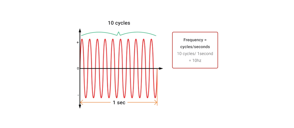
In NZ, the mains supply has a frequency of 50 hertz (Hz) which means it changes direction and back again 50 times per second.
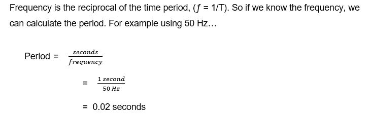
Time Period
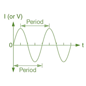 |
The Period, (T) is the length of time it takes in seconds for one complete cycle of the AC signal. The unit of measurement for Period is seconds (s). Period is the reciprocal of frequency, T = 1/ƒ |
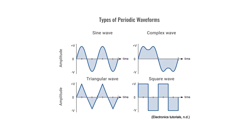
Waveforms
Waveforms are a visual representation of the variation of a voltage or current on the y-axis, plotted against time on the x-axis.
The shape and form of the signal is obtained by plotting the instantaneous values of the quantity.
The most common periodic signal waveforms used in Electrical and Electronic Engineering are the Sinusoidal Waveforms. However, AC waveforms can also take the shape of either Complex Waves, Square Waves or Triangular Waves.
Peak-to-peak
(pk-pk) is the difference between the highest and the lowest values in a waveform. In alternating current (AC) the peak-to-peak value is twice the peak value or 2.828 times the root-mean-square (RMS) value. Peak-to-peak voltage is indicated by VPP.
Wavelength
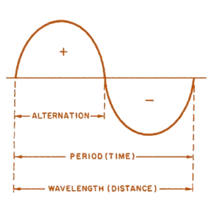 |
Wavelength, symbol Λ (Greek lambda) is the distance along the waveform from one point to the same point on the next cycle. The point on the waveform that measurement of wavelength begins is not important as long as the distance is measured to the same point on the next cycle. |
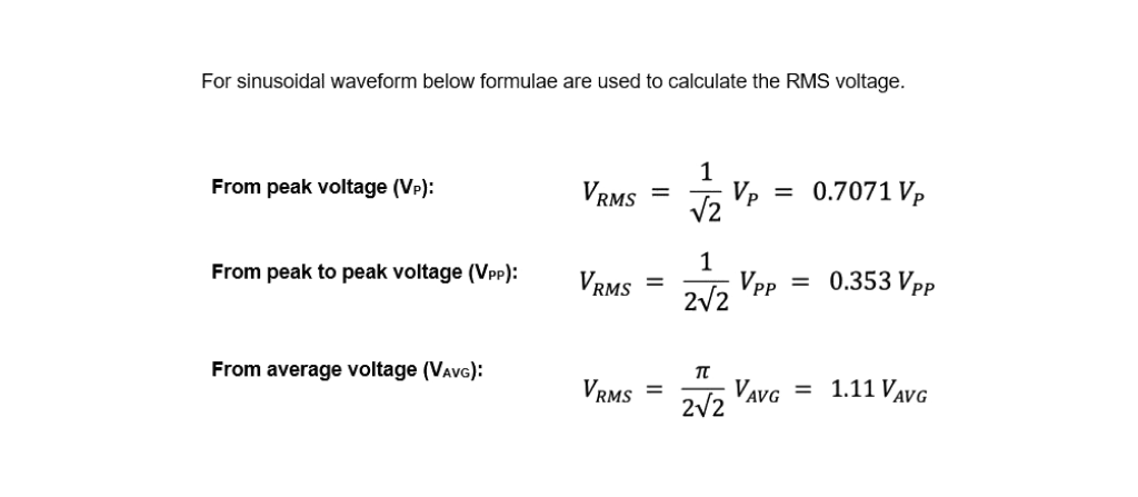
ROOT MEAN SQUARE (RMS)
In practice both peak (or crest) and peak-to-peak forms of amplitude measurement are rarely used. It is more common to express AC voltage in Root Mean Square (RMS) values or Vrms or Irms.
RMS values define the amount of AC power that produces the same heating effect as an equivalent DC power.
RMS amplitude measurement is the best way to relate AC quantities to DC quantities, or other AC quantities of differing waveform shapes, when dealing with measurements of electric power
RMS voltage can be calculated from peak value, peak-to-peak value, and average value.
You can read more about RMS calculations here if you want to test your numeracy skills.
Exercise 23
- Match the terms to their correct definitions
Determine the following for the waveform shown:
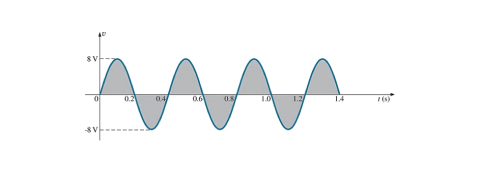
- Determine the following for the sinusoidal waveform shown:
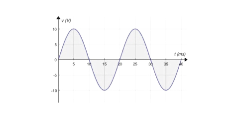
- Peak value.
- Instantaneous value at 15ms and 20ms.
- Peak-to-peak value.
- Period.
- How many cycles are shown?
Self-directed Learning
Test yourself on this multichoice quiz.
- Peak value.
- Instantaneous value at 0.3s and 0.6s.
- Peak-to-peak value.
- Period.
- How many cycles are shown?
- Frequency.