| Day One | Day Two | Day Three | Day Four | |
|---|---|---|---|---|
| Course Content | External influences on cable selection. | External influences on cable selection continued. | Internal influences on cable selection. Short circuit capacity. Current carrying capacity. Voltage drop. Voltage rating. | Internal influences on cable selection. Short circuit capacity. Current carrying capacity. Voltage drop. Voltage rating. |
| Self-directed Learning | Selecting appropriate cable to minimise risk of mechanical damage. | Create checklist of good cable handling techniques. | Re-read the lesson and then answer the self-check questions. | Re-read the lesson and then answer the self-check questions. |
In order for you to gain the most value from your qualification and to prepare you for your assessment and the industry, make sure you complete all of the online and SDL tasks.
What we're covering:
- External influences: temperature, heat, moisture, foreign bodies, corrosion, mechanical damage
External Influences
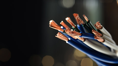
The system of cables used for the transmission of electricity is typically outdoor and subjected to harsh environmental factors which means cables require protection to guarantee proper functioning over a prolonged period and safety. The factors that affect cables can be categorised into ‘Thermal’ and ‘External Influences’.(Havire, 2019)
External influences are any influences external to the cables which can affect the safe operation of the cable and its design. In the previous SDL task, you compared aerial conductors - prone to environmental attack from lightning and windstorms, with underground cables which are more susceptible to ground water infiltration and mechanical damage. External influences include:
- Ambient temperature.
- External heat sources.
- Moisture (rain, humidity, water accumulation).
- Solid foreign bodies.
- Corrosive or polluting substances.
- Mechanical damage and stresses.
- Fauna and flora (animals and plants).
- Hazardous areas.
- Thermal insulation.
- Solar radiation.
Ambient temperature
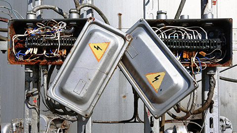
Refers to the temperature of air or any other medium where the cables are installed. Hot and cold temperatures are some of the most critical factors related to cable performance. A rise in the temperature of the conductor increases its resistance and decreases its current capacity. Deterioration of cable insulation is accelerated by hot temperatures - in extreme cases the insulation may melt causing electrocution and fires.
Cold temperatures also have adverse effects on wiring and cables. As cable conductors lose heat, they become less effective. Low temperatures also cause most non-metallic and composite insulating materials to become brittle and inflexible, to the point of breaking.
According to AS/NZS 3000, wiring systems must be selected and installed so as to be suitable for the highest and lowest local ambient temperatures.
Exercise 7
Where current-carrying capacity is selected in accordance with AS/NZS 3008: Part 1.2, what is the reference ambient temperature for cables? Write your answers here.
External heat source
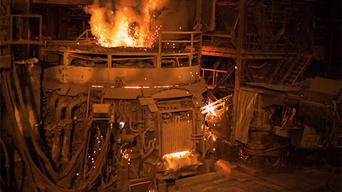
High ambient temperatures are unavoidable in certain situations, for instance commercial kitchens, blast furnaces, coke ovens, and cement kilns. Proximity to adjacent cables will also increase the temperature of the cable.
Exercise 8
With reference to AS/NZS3000 Section 3.3, list four steps you could take to protect wiring systems against the effects of heat from external sources. Write your answers on the same worksheet that you downloaded for Exercise 7.
Moisture (rain, humidity, water accumulation)
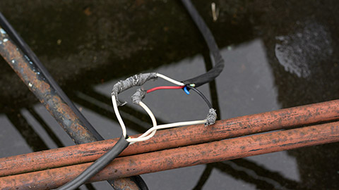
When moisture comes into contact with electrical wiring, it can cause corrosion, short circuits, earth leakages, shocks, and even fires. Moisture may ingress a cable radially, i.e., by permeation through the protective layers (sheaths) or through any breach of these sheaths (mechanical damage), or longitudinally where water enters the cable through ineffective end capping or poorly made joints or terminations.
Solid foreign bodies
Wiring systems should be selected and installed so as to minimise the entry of solid foreign bodies during installation, use and maintenance.
Exercise 9
What are some examples of solid foreign bodies that could enter an installation system? Write your answer on the same worksheet as Exercise 7 and 8.
Corrosive or polluting substances
Corrosion is the deterioration of metals through the combined actions of oxygen, water, other metals and salts. It is a problem for two reasons – the loss of material and additional resistance, resulting in heat development and ultimately in failure.
Aluminium oxidises readily in air forming a hard outer layer of electrically insulating oxide. Copper oxidises to a much lesser extent than aluminium and its oxide is conductive, although not as conductive as the base metal.
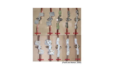
Galvanic corrosion occurs when two electrochemically different metals, in contact with each other, are exposed to an electrolyte. Aluminium is particularly susceptible to galvanic corrosion since it is a relatively reactive metal in the galvanic series. The photographs illustrate aluminium connectors on copper conductor before testing (top) and after 2000 hours of environment testing (bottom).
Exercise 10
According to AS/NZS3000 Section 3.3, what precaution should be taken to reduce the possibility of galvanic corrosion in an installation? Write your answers on the same worksheet as Exercises 7, 8, and 9.
Chemicals coming into contact with cables may also cause corrosion. The cable jacket can swell or harden, eventually cracking to expose the conductors. Chemicals and pollutants include oils (found in machines for lubrication and cutting), acids, cleaning agents, butanone (in degreasers), ammonia and nitrates (used in agriculture), salt (coastal regions), hydrogen sulphide (geothermal regions and forest products processing)
Ground water, or accumulated water in a cable trench that contains corrosive substances may result in corrosion. Similarly, the burning of fossil fuels releases acidic compounds into the air, causing corrosion to aerial and exposed cables.
Mechanical damage and stresses (including vibration)
Mechanical damage to cables can be due to breaks and defects of sheath material, mechanical punctures by people or machines, or cracks due to sharp bending or vibration. Damage may occur during installation by using excessive pulling tension and/or exceeding the minimum bending radius; during maintenance or installation work; or during construction when earth moving equipment severs the cable.
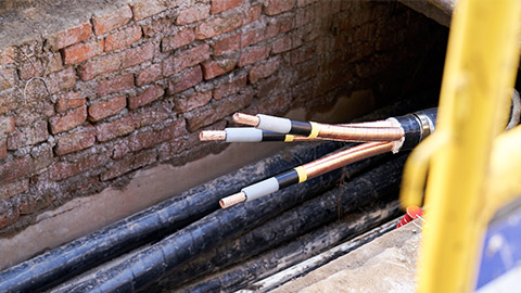
Once mechanical damage occurs in the cable sheath, moisture ingress will cause slow deterioration of insulation material and eventual failure of the cable.
Self-directed Learning
- What factors should be considered when selecting the appropriate cable for a specific application to minimize the risk of mechanical damage to the cable insulation, sheathing, and connections? Provide at least four examples.
- Email your answers to your tutor.
What we're covering:
- External influences: flora and fauna, solar radiation
Fauna and flora
Fauna (animal life) includes insects, small animals and birds. Animal pests like rodents can chew through cable sheaths and the wiring inside resulting in a loss of production and extensive repair works.
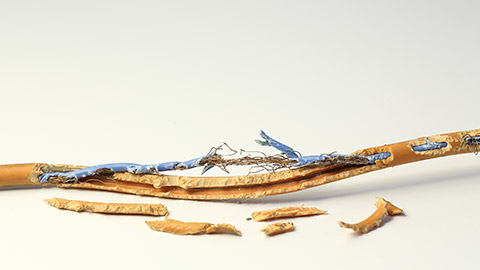
Why do pests and rodents chew cable jackets? Is it a food source? The answer may surprise you: find out in this article 'Rats will devour your car'.
Methods for preventing fauna problems include running cabling in hard conduit pipe and in sealed raceways or using rodent-proof protective layers of cable.
If you are wondering why pests and rodents chew cable jackets – it might be due to a chewing instinct to regulate incisor length (their teeth continue to grow over their lifetime); or an attraction to the cabling (insulating materials can be a food source for insects); or an attraction to the warmth of conductors inside cable jackets, or sensitivity to the electromagnetism of the cabling.
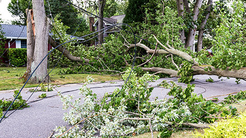
Flora (plant life) also pose problems for installations. In high winds, trees and their debris may blow onto power lines, causing lines to short-circuit, resulting in significant damage to electrical equipment and power cuts. Tree roots that grow around underground electricity cables and rupture insulation cause power supply failure.
Fungal growth on cable insulation may obscure wire identifications, conceal wire/cable damage, and create a health hazard. The presence of mould is an indication of moisture and its associated problems.
Thermal insulation
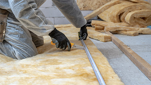
When a cable is run in a space containing thermal insulation, such as walls and ceilings, the operating temperature of the conductors may be exceeded, reducing the current-carrying capacity of the conductors.
According to AS/NZS 3008.1, cables passing through bulk thermal insulation must be rated for current-carrying capacity depending on length of cable passing through the insulation.
Exercise 11
Drag and drop the correct rating for each cable length.
Solar radiation
For any cable exposed to direct sunlight the following effects must be considered:
- Current rating of the cable: Cables are normally rated according to the maximum standard ambient temperature for the given installation, but ambient temperature (and rating factor) will need adjusting to account for the increase in surface temperature of the cable due to solar radiation.
Where would you find guidance on the effect of direct sunlight on the current carrying capacity of cables?
- Physical properties of the cable sheath: UV radiation causes colour fading and degradation of the cable sheath material. Cables likely to be exposed to UV light should be designed with UV resistant materials, although all polymers degrade over time. Depending on the material, it becomes:
- Tough. When exposed to mechanical stress, it cracks and crumbles.
- May change colour or become sticky and lose its insulating properties.
PVC, commonly used in sheath materials and one of the most UV resistant polymers available, eventually changes colour, becomes sticky and loses its insulating properties in the presence of UV. To reduce the effects of UV on cables, stabilisers are added to the PVC compound. The most common of these are Carbon Black and Titanium Dioxide (TiO2).
Exercise 12
Shielding cables from the direct rays of the sun, without restricting ventilation, is the best option for minimising UV degradation. How can this be achieved during installation? Create a 'how to' poster explaining the steps that you would take to do this. Share it in the forum when you have completed it.
Self-directed Learning
As an electrical apprentice, you have been assigned to look after the electric cable drums at your job site. The cost for each 100m 6.0mm 2core+earth flat TPS drum is $720 so it is important they are properly looked after. Write a checklist of the steps you would take to ensure the drums remain in pristine condition.
You may wish to consider the following factors:
- Storage conditions.
- Moisture.
- Environmental Hazards.
- Mechanical Hazards.
- Inspection and Maintenance Procedure.
- Labelling and Documentation.
- Electrical Hazards.
What we're covering:
- internal influences: circuit capacity, current capacity, resistance
Note – sessions 7, 8 and 9 have been designated to cable selection. At the end of the theory and exercises you will find SDL for the topic. Plan your three days accordingly.
Internal Influences
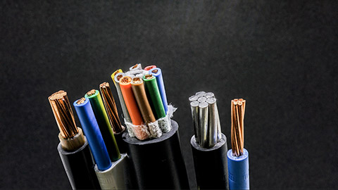
As well as external influences, cable selection depends on:
- Short circuit capacity of cables.
- Current carrying capacity of cables.
- Voltage drop.
- Voltage rating.
Short Circuit Capacity
A cable may be subjected to a short circuit fault current, many times greater than its normal operating current capacity. When choosing a cable, its short circuit capacity must be considered.
Normally the load keeps the current under control, but if that load is bypassed, the current is only limited by the ability of the power supply to supply current and the opposition to current flow of the circuit conductors. Hence under short circuit conditions, extremely high current will flow in a cable causing the cable to overheat.
The heat energy produced in the cable is a product of the square of the fault current and time (I2t).
The insulating material of a conductor has a maximum temperature limit it can withstand before melting. It is essential that under fault conditions, this maximum insulation temperature is not exceeded.
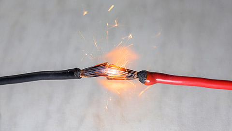
AS/NZS 3008 Section 5 contains tables and calculations regarding short circuit performance of cables. It is a requirement of AS/NZS 3000 that a protection device, such as a circuit breaker, must operate in the prescribed time to clear a fault. The cable needs to be able to cope until it does.
Current Carrying Capacity
All cables and flexible cords used in permanent wiring installations must operate within their design parameters. Cables and cords that do not may be damaged or cause damage to the installation (such as a fire).
The resistance of an electric cable decreases as cross-sectional area increases. A cable with a larger cross-sectional area allows a greater current flow for the same electrical pressure (voltage).
AS/NZS 3008 provides tables to assist with cable selection based on current carrying capacity in different environments. Select the column with the correct environmental conditions and move down to the design circuit current. The cell indicates which size conductor to use for the current.
Try this out for yourself using the AS/NZS 3008 tables.
Current flow in a circuit often varies. Imagine a house with eight double s ocket outlets rated at 10A (x 2 per outlet) on one circuit. It is unlikely all sixteen outlets on that circuit will have a load plugged in and all be drawing the maximum of 10A at the same time (160A in total).Wiring the circuit to cope with 160A all the time would require huge cables and switchgear and is just not necessary. AS/NZS 3000 sets out guidelines for working out a reasonable loading for circuits so you can design an installation that is reliable but not overboard on the size of gear.
The term for this is maximum demand. It is the reasonably normal maximum expected current demand on circuits or an installation. You can work out the maximum demand current and use that to choose the size of your mains cables. AS/NZS 3000 Appendix C contains information on working out maximum demand.
Exercise 13
AS/NZS 3000 2.2.2 provides four methods of determining maximum demand current. List the four methods on this worksheet.
Cable Resistance
The most important factor to consider when selecting cables is the resistance of the conductors in the cable. The resistance of a conductor is affected by its length, thickness, temperature, and the type of material it is made of.
Length of Cable
As the length of a cable or cord increases, so does the resistance of the cable. Resistance is directly proportional to length of the conductor.
- The shorter the conductor, the lower the resistance.
- The longer the conductor, the higher the resistance.
Exercise 14
Use the data provided in the table in the worksheet you downloaded for Exercise 13 to graph the relationship between conductor length (along the x-axis) and the three measurements voltage, current and resistance. You should draw 3 separate lines, with a key identifying each parameter.
Cross Sectional Area of Cable
Resistance is inversely proportional to the cross-sectional area of the conductor
- The greater the conductor area the lower the resistance.
- The smaller the conductor area the greater the resistance.
If the cross-sectional area of the conductor is doubled, its resistance gets halved.
Temperature of the Conductor
The resistance of metals increases with a rise in temperature. (The resistance of alloys increases very slightly with a rise in temperature.) Resistance is directly proportional to the temperature of the conductor.
- The higher the conductor temperature, the higher the resistance.
- The lower the conductor temperature, the lower the resistance.
Temperature makes a significant difference to the resistance of a conductor. The conductor may be used in a cool store with an ambient temperature of -20°, or in a commercial kitchen where the temperature reaches 45°.
Resistivity of the Conductor
Some materials have low resistance, whereas some others have much higher resistance. In general, an alloy has higher resistance than the pure metals which form the alloy.
- Copper, silver, aluminium etc., have very low resistance.
- Nichrome, constantan etc., have higher resistance. Nichrome is used for making heating elements of heaters, toasters, electric iron etc.
The following table summarises these four factors affecting resistance:
| Factor | ||||
| Graph |
The learning for this topic is continued in Lesson 8.
What we're covering:
- internal influences: voltage drop
Lesson 8 continues the learning started in Lesson 7.
Voltage Drop
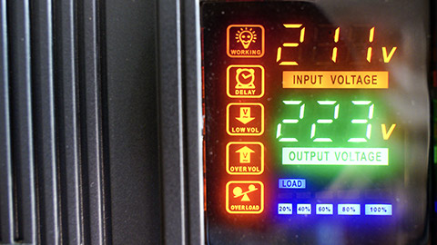
Voltage drop occurs when the voltage at the end of a run of cable is lower than at the beginning. Any length of wire has some resistance, and running a current through this resistance will cause the voltage to drop.
So why is this a problem? When too much voltage is lost in a cable, lights flicker or burn dimly, heaters heat poorly, and motors run hotter than normal and burn out. The load must work harder with less voltage available to push the current.
Watch the first 6 minutes of the following video explaining Voltage Drop then answer the questions in the worksheet below.
Exercise 15
Maximum Voltage Drop
AS/NZS 3000 3.6.2 stipulates the maximum allowable voltage drop between the point of supply for a low voltage electrical installation and any point in that installation, can be no more than 5% of the nominal voltage at the point of supply.
The maximum voltage drop is the amount that is considered a reasonable maximum to “lose” in the cables. For example, if the supply voltage to an installation is 230V then the voltage at any point in that installation cannot be lower than 218.5V. As a “rule of thumb”, when selecting a single cable for an installation, allow for a maximum volt drop of 2.5% per cable. Cable tables usually give voltage drop figures as mV/A/m, pronounced as ‘millivolts per amp per metre’.
This is a measure of the amount of voltage a circuit loses, measured in millivolts, for every amp flowing through every metre of the circuit. When 20 amps flows in a 10-metre-long cable with a rating of 18.92 mV/A/m, 18.92mV is lost for every amp and every metre of cable.
i.e., 18.92 x 20 x 10 = 3784mV or 3.784V in total.
Calculating Voltage Drop
When the route length and circuit current are known, AS/NZS 3000 Table C8 may be used to determine:
- The required cable size for a specified percentage voltage drop in the circuit.
- The percentage voltage drop that a particular cable will provide.
Read AS/NZS 3000 Section C4 - Simplified Voltage Drop, ensuring you understand the two examples provided – C4.2.
To calculate the percentage voltage drop for a circuit, multiply the current (amps) by the cable length (metres); then divide this number by the 'Am per %Vd' (amp metres per % voltage drop) for the cable size found in Table C8.
Exercise 16
Use the formula above and the values from Table C8 to answer the questions on the worksheet that you downloaded for Exercise 15.
When you need to find the actual voltage drop (not just percentage voltage drop) refer to the AS/NZS 3008.1 series. The formula used is:
where
Vd = actual drop (V)
L = route length of the circuit (m)
I = circuit current - usually maximum demand (A)
Vc = cable voltage drop per ampere-metre length of the circuit (mV/A)
(Tables of Vc values found in the AS/NZS 3008.1 series.)
Fortunately, you can find numerous online calculators to work out cable size or voltage drop for you. Have a look at this one and use it to check your answers from the previous exercise.
If the calculations for a particular cable indicate the voltage drop is too high, you will need to increase the size (cross section) of your conductors to lower the overall resistance of the cable length. Be mindful however - larger copper or aluminum cable sizes will increase cost, so it’s important to find the optimum cable size that reduces voltage drop to safe levels while still remaining cost-effective.
When selecting a single cable for an installation, allow for a maximum volt drop of 2.5% per cable.
Bunched cables
Heat is a major concern for bunched circuits. When multiple cables are installed together and each is carrying current, they will all warm up. Cables on the outside of the group will transmit some heat outwards, but for cables in the centre of the bunch it may be impossible to shed heat at all, causing a further rise in temperature. Because of this, a cable’s current-carrying capacity decreases when it is installed in a group i.e., in a tray, conduit or trunking etc. AS/NZS 3008.1.2 contains tables that give current carrying capacity derating factors for cables installed with others in groups.
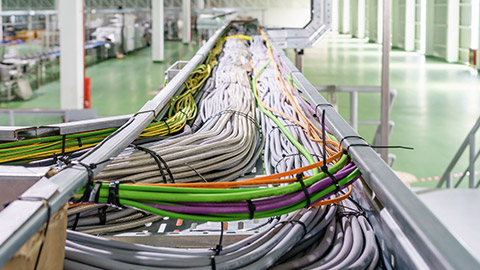
For example, if a certain cable has a basic current rating of 32 A and is installed in a trunking with four other circuits, the derating factor, Cg, has a value of 0.60 and the cable current rating becomes 32 x 0.60 or 19.2 A. Note these grouping factors are based on the assumption that all cables in a group are carrying rated current.
Appendix D of AS/NZS 3008 gives suggested circuit configurations to minimize these effects when cables are grouped together.
Current Derating Factors
Derating factors or correction factors are applied when a cable is unable to carry its designated value. Current carrying capacity is affected by such factors as laying method and depth, air and soil temperature, cable formation etc. If a cable has a derating factor of 0.75 this means the cable can only provide 75% of its rated current capacity so we should choose a higher current capacity cable to compensate for the drop.
The learning for this topic is continued in Lesson 9 in Week 3.
