| Day One | Day Two | Day Three | Day Four | |
|---|---|---|---|---|
| Course Content | Internal influences on cable selection. Short circuit capacity. Current carrying capacity. Voltage drop. Voltage rating. | Conductor size. | Connection to appliances. Extension cords and appliance cords. Plugs and sockets. Multiphase cords and plugs. Cord supports. Appliance Insulation Classification. | Connection to appliances. Extension cords and appliance cords. Plugs and sockets. Multiphase cords and plugs. Cord supports. Appliance Insulation Classification. |
| Self-directed Learning | Re-read the lesson and then answer the self-check questions. | Selection of cord size review questions. | Three-phase electrical system scenario. Comparison chart - Class I, II, III equipment. | Three-phase electrical system scenario. Comparison chart - Class I, II, III |
In order for you to gain the most value from your qualification and to prepare you for your assessment and the industry, make sure you complete all of the online and SDL tasks.

What we're covering:
- Internal influences: voltage rating
The content in lesson 9 continues from lesson 8.
D. Voltage Rating
It is important that the cables to be installed have a voltage rating suitable for the supply potential they will be connected to. The voltage value of electrical equipment for which it is designed to be used is called nominal voltage. The maximum voltage that can be applied to equipment safely is called rated voltage.
Nominal voltage is the voltage that the circuit-breaker is designed to be used at, whereas rated voltage is the maximum voltage that the circuit-breaker can interrupt safely and without being damaged by unnecessary arcing.
The rated voltage value must be greater than the nominal voltage, for the safe functioning of equipment.
The actual voltage at which a circuit operates can vary from the nominal voltage, within a range that permits satisfactory operation of equipment. Vector provides:
‘A nominal voltage of 230 volts ± 6% for single phase and 400 volts ± 6% for three phase at your point of supply, except for momentary fluctuations as allowed by the Electricity (Safety) Regulations 2010.’
The voltage rating of a cable may appear on the cable sheath or on the drum label. A common value is 0.6/1kV which means the maximum working voltage is 600V AC between any conductor to earth and 1000V AC between adjacent conductors.

Another common voltage rating for cables is 450/750V.

Self-directed Learning
Read through the content from this topic – there is a lot to take in! Make sure all the exercises have been completed then answer these questions to check your understanding. Write your answers on a piece of paper and take them into class for your tutor to check or email your answers to your tutor.
- What is the short circuit capacity of a cable and why is it important to consider when selecting a cable?
- What factors affect the current carrying capacity of a cable?
- What is the consequence of selecting a cable with a current carrying capacity that is too low for the application?
- Why is it important to ensure that the short circuit capacity of a cable is higher than the maximum short circuit current that may occur in the electrical system?
- How can the current carrying capacity of a cable be increased?
- Use an online voltage drop calculator tool to calculate the voltage drop of the following cables:
- 2.5mm² copper wire with a length of 30 m, carrying a current of 5A, used for lighting circuits in a residential building, where the current requirement is low and the distance between the power source and the load is relatively short.
- 6mm² aluminum wire with a length of 20 m, carrying a current of 15A, used for a medium-sized air conditioning unit in a commercial building, where the current requirement is higher than a lighting circuit and the distance between the power source and the load is relatively short.
- 50mm² copper welding cable with a length of 10 m, carrying a current of 200A, where the current requirement is very high, and the cable must be flexible to accommodate movement during the welding process.
- Compare the calculated voltage drop to the maximum voltage drop allowed for the application. Some examples of maximum voltage drop limits for typical applications, based on AS/NZS 3008.1.1:2017 are:
- Lighting circuits: 3% voltage drop.
- Air conditioning circuits: 2.5% voltage drop.
- Welding circuits: 10% voltage drop.
- Discuss the importance of voltage drop in cable selection and the consequences of selecting a cable with a high voltage drop

What we're covering:
- Determining conductor size
- Cable markings
While different wires have specific purposes, choosing the right wire size or gauge is crucial to the overall cost, performance, and safety of your installation. Correct cable selection also ensures compliance with AS/NZS 3008.
You may have come across the American Wire Gauge (AWG) and the British Standard Wire Gauge (SWG) systems used to describe wire size, where the smaller the wire gauge number, the larger the diameter of the wire.
New Zealand uses the standard wire cross-sectional areas defined by the IEC. Describing a wire in terms of its cross-sectional area is more useful than describing its diameter since cross-sectional area is directly proportional to its strength and weight, and inversely proportional to its resistance. Cross-sectional area also relates to the maximum current a wire can safely carry.
To determine what gauge wire you need, consider the carrying capacity and the amount of current the wire needs to conduct. The distance you need the wire to run can also impact the choice of wire gauge.
Numerous online conversion charts and calculators are available for converting between AWG and metric sizing.
Exercise 17
Research some of these charts and calculators and use them to answer the questions in this worksheet.
Exercise 18
Refer to the ECP 51 - New Zealand Electrical Code of Practice for Homeowner/ Occupier's Electrical Wiring Work in Domestic Installations (NZECP 51:2004) to find the correct wire size to use for these types of circuit. Complete the table provided in the worksheet you downloaded in Exercise 17.
Determining Conductor Size
Sometimes conductors have the size marked on them, but when they don’t you may need a method for determining their size. It is very difficult to estimate just by looking at the end of a cable! Selecting an incorrect size cable could be expensive in the case of oversize cable or a potential fire risk if the cable is undersize.

Your tutor will demonstrate some of the practical ways you could measure the size of a conductor. Make sure you are familiar with the various methods which might include:
- A screw gauge or micrometer (electronic or mechanical).

- A wire gauge consisting of a metal plate (typically circular or rectangular) with holes drilled around its perimeter corresponding to numerous wire sizes. Each hole is labelled with - and corresponds to - a different gauge size. Insert the bare conductor into the holes to find the best fit. Gauges are generally two-sided - SWG /Metric, AWG/Metric, or SWG /AWG.

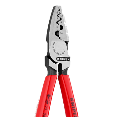
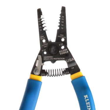
- Often multi-purpose pliers or wire strippers also show wire sizes. Make sure to buy a metric set when you are starting out.
 |
 |
 |
- Compare the wire against another wire whose gauge is known. For example, if you have a small-diameter section of wire, hold it next to wires of known gauge such as 0.5, 0.75 and 1.0 mm2 to see which wire your segment matches. Start collecting strands of various sizes of wire for future reference when you are working in the trade.

- Use a crimp lug to slip it over the cable to check the size.

Cable Markings
All the information you need to know about a type of cable is usually printed on its sheathing. This may include information about:
- Type of cable.
- Type of conductor.
- Presence of a grounding or earthing wire.
- Insulation used.
- Voltage rating.
- Temperature rating.
- Metre markings indicating how much cable has been used.
- Size and number of the individual conductors inside the cable e.g., 1mm2 – 32/0.2 cable has 32 strands of wire, each with a 0.2mm diameter.
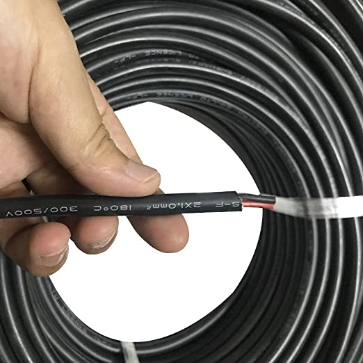
For instance, a cable marking of V-90 2.5 mm2 means the cable insulation is rated up to a maximum of 90°, has 2.5 mm2 conductors and has voltages rating as below.
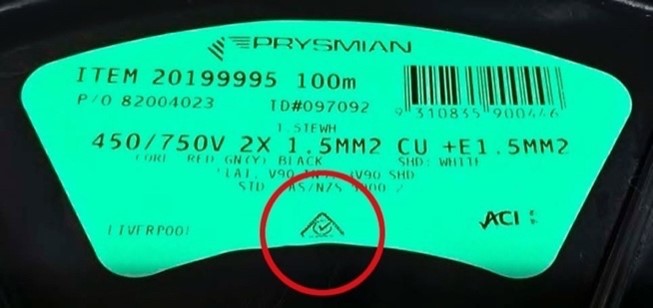
Manufacturers also include useful information on the cable drum labels.
Exercise on Cable Labels
This is included on the worksheet you downloaded for Exercise 17 and 18.
Guided Exercise
Work through the solution to the following problem, making sure you understand how each step was calculated.
A 240-volt single-phase air conditioner with a 20-amp load is located 30 m away from the power source. Use the AS/NZS 3008.1.1:2017 standard to calculate the minimum conductor size required for this application.
Solution:
1. Determine the load current: The load current is given as 20 amps.
2. Determine the voltage drop: (A maximum voltage drop of 5% for single-phase AC circuits is recommended in NZ.)
Using AS/NZS 3008.1.1:2017 the voltage drop can be calculated as follows:

Where:
Length = distance between power source and air conditioner, in metres
Load Current = 20 amps
Cross-sectional area = unknow, we will calculate this
Conductivity = 56.0 x 10² Siemens/metre (for copper conductors)
Plugging in the values, we get:

Rearranging this equation, we get:

3. Determine the resistance of the conductor: The resistance of the conductor can be found from the standard's tables. For a copper conductor, the resistance is 0.0085 ohms/metre.
4. Calculate the minimum cross-sectional area: Plugging in the values, we get:

A = 2.1 x 10⁻⁶ m2 or 2,100 mm2
Therefore, the minimum conductor size required for this application, according to the AS/NZS 3008.1.1:2017 standard, is 2,100 mm2.
In practice, this cable size may not be available, and the next largest standard cable size should be used instead.
Exercise 19
Complete the exercise on the worksheet that you downloaded earlier.
Self-directed Learning
Download the worksheet to complete the following exercises.
- Suggest at least one application for each of the following cables based on the conductor size and other information found on the label.
- TRS 1.5mm² 450/ 750V
- V-90 2.5mm² 450/ 750V
- NZXT 4mm² 450/750V
- What is the primary factor that determines the appropriate conductor size for an electrical installation in NZ?
- Why is it important to select the right cable size for an electrical installation?
- What are some consequences of using an undersized cable for an electrical installation?
- Complete the table which shows the information typically provided on the cable insulation and its importance in cable selection.

What we're covering:
- Flexible cord
- Plugs and sockets
Note – The next three sessions cover connection to appliances. At the end of the theory and exercises you will find SDL for the topic. Plan your three days accordingly.
Flexible Cords
Flexible cords are used to connect electrical equipment to a power source. They are designed to be routinely flexed. Flexible cords may have an electrical plug that connects to a power source, or they may be permanently wired into a power source. Extension cords (cord sets), cables, and appliance cords are types of flexible cords.
Extension Cords
An extension cord is a length of flex with a plug on one end and a socket on the other end (usually of the same type as the plug). They tend to be used in situations where they are prone to damage – the insulation may be pinched, crushed, or scraped; the plug and socket connections may be pulled on excessively; overloading may cause the insulation to melt etc. Extension cords must be tested and tagged at specific time intervals when they are used commercially.

Note - extension cords can only carry full rated current when completely extended. If the cord is coiled up the heat produced from the resistance cannot dissipate and is instead trapped between the tightly coiled cable, resulting in fire or shock.
Appliance cords
An appliance cord is used to connect appliances to a power supply. It is made from insulated, flexible electrical cable with connectors at one or both ends.

One end is typically a male connector (recognised by its unshielded electrical prongs when it is disconnected) that goes into the wall outlet or extension cord. The other end is a female connector that is attached to the appliance or to another male connector. The female connector has one or more recessed holes with electrical terminals inside and is constructed in such a way that a plug with exposed conductors (a male connector) can be inserted snugly into it. This female connector is sometimes omitted in appliances and replaced by a fixed cable.

Plugs and Sockets
There are currently 15 different styles of outlets and plugs commonly used around the world.

New Zealand, Australia and the Pacific Islands use Type I plugs. Type I plugs have three flat pins in a triangular pattern - two angled at the top and one straight underneath.

Socket Configurations
Plug tops and sockets are available in a range of pin styles and configurations. This convention prevents an appliance being supplied from socket outlets of a higher current rating. (A plug can be inserted into a socket of the same or higher rate, but not in a socket with a lower rate.)
Standard single phase 230 V domestic socket outlets in Australia and New Zealand are rated at 10 A. Some single-phase plug and socket configurations are shown:
| Rating | Socket Image | Description |
|---|---|---|
| 10A 250V |  |
Standard domestic configuration _ three flat pins - phase, neutral, and the largest - the earth pin. |
| 15A 250V | 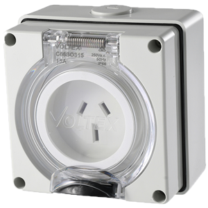 |
Wider Earth pin than the 10 A outlet. |
| 10A 250V | 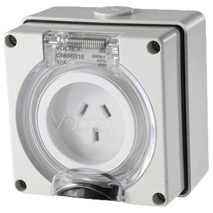 |
Configuration for special purposes - flat phase and neutral pins and round earth pin _ such as "off peak" storage heaters etc. |
| 20A 250V | 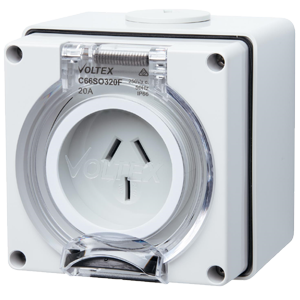 |
Wider earth and wider phase and neutral pins than the 10 A outlet. |
| 10A 250V | 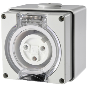 |
Suitable for utility, industrial and small commercial installations. |
| 20A 250V | |
Suitable for most industrial and commercial applications. |
| 32A 250V | 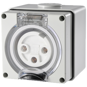 |
Industrial strength power plugs for dusty or wet conditions. |
Voltage and Current Rating
As we have seen, a plug top must have a voltage and current rating not less than that of the appliance it supplies and its intended socket. Sockets accept equal and lower rated plugs, so a 32A outlet accepts 32A, 25A, 20A, 15A, 10A and 7.5A plugs, but a 10A outlet will only accept 10A and 7.5A plugs.
Ingress Protection (IP) Rating
An IP mark, (also referred to as an International Protection mark) is a two-digit grading system applied to electrical equipment. The IP rating denotes:
- Resistance to ingress, accidental or otherwise, by the user.
- Resistance to ingress from foreign bodies (dust, dirt etc.).
- Resistance to moisture ingress.
The first digit will be a number between 0-6 and indicates the degree of protection from ingress of solid objects, while the second digit will be a number between 0-9, denoting the quality of resistance to moisture ingress at varying intensities, angles, depths and pressures of exposure or immersion.
An IP66 rating means the fixture is protected against dust, dirt, sand, and debris (indicated by first “6” digit)and is water resistant against powerful jets (indicated by second “6” digit)

An explanation of IP ratings is available in AS/NZS 3000 Appendix G.
Exercise 20
Why is it useful to have a universal rating system? Email your answer to your tutor.

What we're covering:
- Multiphase cords and plugs
- Flexible cord entry supports
This content continues from Lesson 11.
Multiphase Cords and Plugs
In a three-phase supply system, there are two different levels of voltage - the lower voltage is the 'Line to Neutral Voltage' which is the measured voltage between one of the three lines and the neutral, and the higher voltage is the 'Line to Line Voltage'.
For instance, in a 400/230V three-phase and neutral system, voltage between any two phases/lines is 400V and voltage between any phase/line and neutral is 230V.

This setup allows you to connect a three-phase load in a way that each phase will have either 230V or 400V across them or connect a single-phase load that needs 230V across one phase and neutral.
Multiphase Plugs and Socket Outlet Configurations
Multiphase plugs and socket outlets are available in a wide range of styles. They are rated up to 500 V and all include an earth connection.
Three-phase plugs and sockets are available as 4-pin (without neutral) or 5-pin (with neutral). A plug without a neutral pin can be inserted into a socket carrying neutral, but the reverse is not possible since there is hole for the neutral conductor.

AS/NZS 3123 groups three-phase, round-pin sockets according to their current rating and neutral circuit:
| Group | Maximum Current Rating | Neutral Circuit | Neutral Conductor Colour |
|---|---|---|---|
| 1 | 10 amps | N | N/A |
| 2 | 20 amps | Y | Light Blue |
| 3 | 32 amps | Y | Light Blue |
| 4 | 50 amps | Y | Light Blue |
| 5 | 50 amps | Y | Black |
| 6 | 50 amps | Y | White |
The selection of the appropriate group depends on the specific application and the maximum current rating required. It is also important to connect the load to the appropriate phase conductors and neutral conductor according to the colour coding specified for that group.
Exercise 21
Download this worksheet and answer the questions. When the entire worksheet is complete, bring it to class for your tutor to check.
Each socket in the group accepts plugs in the same group up to its rating but excludes plugs with a higher current rating; from a different group; or with a neutral pin (if there is not one in the socket).
| Plugs | Sockets | ||||||||||||||||
| Group | Voltage | Current | 110V 1ph | 250V 1ph | 415-500V 3ph | ||||||||||||
| Group 5/6 | Group 1/2 | Group 7/8 | Group 3/4 | Group 9/10 | Group 11/12 | Group 13/14 | |||||||||||
| 32A | 10A | 20A | 32A | 10A | 20A | 32A | 40A | 50A | 50A | 63A | 80A | 100A | 160A | 200A | |||
| 5/6 | 110V 1ph | 32A | ✔︎ | X | X | X | X | X | X | X | X | X | X | X | X | X | X |
| 1/2 | 250V 1ph | 10A | X | ✔︎ | ✔︎ | X | X | X | X | X | X | X | X | X | X | X | X |
| 20A | X | X | ✔︎ | X | X | X | X | X | X | X | X | X | X | X | X | ||
| 7/8 | 250V 1ph | 32A | X | X | X | ✔︎ | X | X | X | X | X | X | X | X | X | X | X |
| 3/4 | 415 - 500V 3ph | 10 A | X | X | X | X | ✔︎ | ✔︎ | X | X | X | X | X | X | X | X | X |
| 20 A | X | X | X | X | X | ✔︎ | X | X | X | X | X | X | X | X | X | ||
| 9/10 | 415 - 500v 3ph | 32 A | X | X | X | X | X | X | ✔︎ | ✔︎ | ✔︎ | X | X | X | X | X | X |
| 40 A | X | X | X | X | X | X | X | ✔︎ | ✔︎ | X | X | X | X | X | X | ||
| 50 A | X | X | X | X | X | X | X | X | ✔︎ | X | X | X | X | X | X | ||
| 11/12 | 415 - 500v 3ph | 50 A | X | X | X | X | X | X | X | X | X | ✔︎ | ✔︎ | ✔︎ | X | X | X |
| 63 A | X | X | X | X | X | X | X | X | X | X | ✔︎ | ✔︎ | X | X | X | ||
| 80 A | X | X | X | X | X | X | X | X | X | X | X | ✔︎ | X | X | X | ||
| 13/14 | 415 - 500v 3ph | 100 A | X | X | X | X | X | X | X | X | X | X | X | X | ✔︎ | ✔︎ | ✔︎ |
| 160 A | X | X | X | X | X | X | X | X | X | X | X | X | X | ✔︎ | ✔︎ | ||
| 200 A | X | X | X | X | X | X | X | X | X | X | X | X | X | X | ✔︎ | ||
For example, there are two groups both consisting of 10 A and 20 A connectors. The 10 A plug from the first group can be connected to either the 10 A or 20 A sockets in this group, but it cannot be connected to either the 10 A or 20 A sockets in the second group. This means there are two different, incompatible 10 A connectors that are not interchangeable as they are physically different sizes.
How is this load matching achieved?

The diagram shows a 3-phase 50A 5 pin 500VAC socket and plug, both viewed from the front. The neutral connection is always in the centre and the earth pin oriented downward. The three phase conductors are connected clockwise from the earth pin when looking at the back of the plug top.
Flexible Cord Entry Supports
Because they are exposed, bendable, and unsecured, flexible cords are more prone to damage than fixed wiring. The cord entry points into the terminal boxes of equipment, and into plug tops also require extra support.

- Cable glands, also called grip clamps, secure and seal cables in place, preventing them from being twisted or pulled out. They also form an environmental seal and provide earth continuity ensuring the protection of electrical equipment and enclosures.
- Cable clamps are devices used to bundle, clamp, guide, and protect wires and cables. They act as a guide, supporting cables whilst restricting movement. They are important when space is limited space or when flexibility is needed.

- Strain relief bushings or grommets protect cables from rubbing and abrasion when they pass through holes in metal panels. Bushings are available for both flat and round cables.

Flexible cords connected to electrical appliances have been designed to have a specific length depending on the type of appliance, its load demand, and the environment in which it operates.

Electrical equipment may be connected to the installation wiring by one of the methods detailed in AS/NZS 3000:2018 Clauses 4.3.2 to 4.3.5. In addition, Clause 4.3.6 places restrictions on equipment wiring such as:
- A maximum flexible cord or cable length of 2.5 metres.
- A current-carrying capacity not less than the maximum load of the connected appliance (or luminaire).
- A minimum cross-sectional area of 0.75 mm2.
- Protection against short circuits (in accordance with Clause 2.5.4).
- A protective earthing conductor contained within the sheath which meets the protection requirements according to the load.
Also refer to AS/NZS 3100, AS/NZS 3012 and AS/NZS 3760 when determining the correct cord length to use.
Exercise 22
Answer the questions on the worksheet you downloaded for Exercise 21.
