| Day One | Day Two | Day Three | Day Four | |
|---|---|---|---|---|
| Course Content | Connection to appliances. Extension cords and appliance cords. Plugs and sockets. Multiphase cords and plugs. Cord supports. Appliance Insulation Classification. | Electrical appliances | Inspection and testing of cords, appliances and RCDS. | Cable support systems. Moisture and fire barrier ratings for cable penetrations. |
| Self-directed Learning | Three-phase electrical system scenario. Comparison chart - Class I, II, III | Certificate of Compliance (CoC). Electrical Safety Certificate (ESC). | Inspection and testing of compliance on a building site. | Fire-rated penetration seals. |
In order for you to gain the most value from your qualification and to prepare you for your assessment and the industry, make sure you complete all of the online and SDL tasks.
What we're covering:
- preparing a flexible cord
- connecting plugs and sockets
Note - this content continues from Lesson 12.
Preparing a Flexible Cord
Refer to NZECP 50:2004 NZ Electrical Code of Practice for Repair and Maintenance of Domestic Electrical Appliances by the Owner of the Appliance. Section 3.2 Preparing a Flexible Cord explains how to remove the outer sheath of flexible cord.

Your tutor will demonstrate acceptable techniques and give you an opportunity to practice. The following videos also demonstrate some methods and tools you could use to strip cords and cables.
-
How to strip electrical cable
-
How to strip electrical wire
-
How to strip electrical wire like a prop
Connecting Plugs and Sockets
Again, instructions for fitting a 3-pin plug or socket to a flexible cord can be found in NZECP 50:2004 NZ Electrical Code of Practice for Repair and Maintenance of Domestic Electrical Appliances by the Owner of the Appliance - Section 3.3 Attaching a 3-pin plug or socket to a flexible cord.
Alternatively, this video which provides a straightforward explanation:
- Strip the insulation to the length stipulated in the wiring instructions.

- Insert strands into correct terminals of the plug or socket and secure tightly.
- Place the cord sheath under the loosened cord grip and tighten to prevent the braiding or sheath creeping back up the cord and exposing internal cables.
- Cover any exposed internal cable cores with insulation tape.
- Secure the outer cover over the plug top.

Tip - when wiring a length of 3-core flexible cord to a 3-pin plug, select the ‘correct’ end of the cord by spreading the wires apart and holding them up against the plug. They should be aligned with the correct terminal without crossing over each other.
Portable single-phase appliances are usually connected to the power supply by means of a flex and a 3-pin 230V 10A plug or 230V 15A plug.
Appliance Insulation Classifications
Low voltage electrical appliances are classified according to their level of insulation:
- Class I equipment (basic insulated, protectively earthed equipment).
- Class II equipment (double insulated equipment).
- Class III equipment (fitted with an isolation transformer to isolate device from power source).
Single Insulated (Class I) - AS/NZS3760 defines Class I appliances as having two levels of protection: basic insulation between the internal live components and the outer metal enclosure; and an earth connection for all conductive accessible parts. If the basic insulation fails, the earth connection acts as the next level of protection.
| Class I Appliances can be identified by this earth symbol. |  |
Appliances include refrigerators, microwaves, kettles, irons, and toasters.
Double insulated (Class II) - Class II appliances have two layers of insulation - primary insulation (closest to the electrical parts) and secondary insulation (the non-conductive casing of the appliance). Double insulation removes the need for an earth connection. Double insulated appliances must NOT have exposed metal connected to earth.
| Class II Appliances can be identified by this symbol to indicate double insulation - one square inside another. |  |
Equipment may also have a warning label such as ‘DO NOT EARTH – DOUBLE INSULATED’.
Examples of Class II appliances include hair dryers, televisions, computers, plastic power tools, and photocopiers.
| Class III appliances are fitted with an isolation transformer, which transfers electrical power from an AC source to an electrical device while isolating the device from the power source. |  |
Examples of Class III electrical appliances include laptops, mobile phones, and low-energy light bulbs.
Exercise 23
Match the following descriptions with the correct class of electrical equipment.
Self-directed Learning
Download the SDL worksheet here.

A factory in New Zealand needs to install a new three-phase electrical system and is choosing a suitable round-pin socket. The first step is to determine the voltage and current requirements of the three-phase electrical system that will be installed. This includes the number of phases, the voltage level, and the current rating. Based on the electrical system requirements, the factory should choose a suitable round-pin socket that is rated for the required voltage and current and made of high-quality materials to ensure durability and safety. The standard round-pin socket for three-phase electrical systems is a 56 series socket. Next the factory should determine the socket configuration needed for their specific electrical system. This includes the number of pins, the pin arrangement, and any other specific requirements for the socket. The standard socket configuration for three-phase electrical systems is a four-pin socket, with the pins arranged in a circular pattern.) The socket enclosure should be chosen based on the environmental conditions in which the socket will be installed. The enclosure should provide protection against moisture, dust, and other hazards, and should be made of high-quality materials to ensure durability. (The standard socket enclosure for three-phase electrical systems is an IP66 rated enclosure.) Before installing the three-phase electrical system and round-pin socket, the factory should check local electrical regulations to ensure compliance with all safety and code requirements. They may need to obtain a permit or have the installation inspected by a licensed electrician.
Task 1
Answer the questions about the scenario on the worksheet provided.
Task 2
Create a chart that compares and contrasts the advantages and disadvantages of Class I, Class II, and Class III electrical equipment. Provide at least three advantages and three disadvantages for each class.
What we're covering:
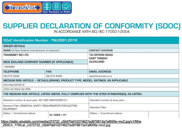
- SDoC
- Installation and Connection of Appliances
- Testing and Compliance
Testing & Compliance
An electrical appliance is a device that is powered by electricity and performs a specific function or task. Common electrical appliances include refrigerators, washing machines, air conditioners, and televisions.

The Electricity Act 1992 defines electrical appliances as:
“Any appliance that uses, or is designed or intended to use, electricity, whether or not it also uses, or is designed or intended to use, any other form of energy.”
To ensure safe and effective installation you must consider several factors when installing an electrical appliance, including electrical load, voltage, location, grounding, wiring, circuit protection, installation instructions, declaration of conformity and manufacturer’s instructions.
Exercise 24
Answer the question on the worksheet here. Ask your tutor to check your answers when you are in class next.
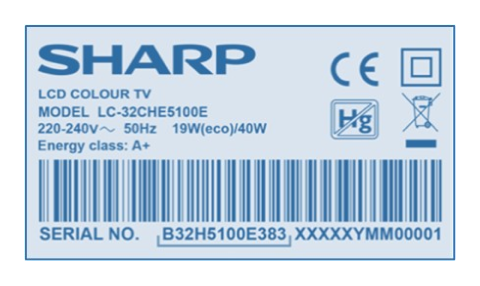
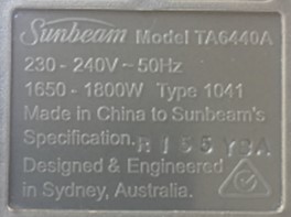
- Input specifications and ratings: The input specifications and ratings refer to the electrical requirements of the appliance, such as the voltage, frequency, and current rating and are typically listed on the appliance's label or in the user manual. You must consider these specifications when installing the appliance and ensure that the electrical system can provide the required input power.
- Control and power circuits: Electrical appliances typically have two types of circuits: control circuits and power circuits. Control circuits are used to control the operation of the appliance, such as turning it on and off, adjusting the temperature, or selecting a program. Power circuits are used to provide the energy needed to operate the appliance, such as heating elements or motors. You must ensure both circuits are working correctly for the appliance to operate safely and effectively.
- Electrical protection for appliances: Electrical protection is essential to prevent damage to the appliance and to ensure the safety of the users. Electrical protection devices include fuses, circuit breakers, and surge protectors. Use appropriate electrical protection devices to prevent electrical overloads, short circuits, and voltage surges.
- Appliance output: The appliance output refers to the results or output that the appliance produces, such as heat, light, or sound. Ensure the appliance output meets the user's needs and that it is safe and effective.
- Environment: The environment an electrical appliance operates can also affect its performance and safety e.g., appliances may need to be kept away from heat sources or in a well-ventilated area to prevent overheating.
- Energy efficiency: Choosing energy-efficient appliances can help to reduce your energy consumption and lower your electricity bills. Look for appliances that have a high energy rating or are certified by energy-saving organisations.
Examples:
| Appliance |
4 slice toaster |
| Input specifications and ratings | An 1800W toaster, requires a 10A socket and a 230V supply. The connection method needs to be rated correctly for the supply it is to be connected to. |
| Control and power circuits | Control circuits consist of a timer, a temperature control thermostat, and a switch that turns the heating elements on and off. Power circuits consist of two heating elements, made of nichrome wire, and a bimetallic strip that opens and closes the circuit to control the temperature. |
| Appliance protection |
The appliance is a Class I appliance and is earthed. Bimetal strip bends when heated, causing a switch to open and cut-off power to the toaster. (Strip returns to original position when cool, allowing normal operation to resume.) Thermal fuse breaks the circuit and cuts off power to the toaster in the event that the temperature inside the toaster exceeds a safe level. It cannot be reset. |
| Appliance output | Electrical energy is converted to heat energy by the nichrome wire heating elements causing the bread to become toasted. |

Exercise 25
Answer the questions on the worksheet that you downloaded for exercise 24.
Installation and Connection of Appliances
In the NZ Wiring Rules (AS/NZS 3000:2018 Electrical Installations), there are 14 fundamental installation principles that represent a set of core requirements to be followed throughout the installation process, from design and selection of equipment to inspection and testing. While they are not listed in a single section, they are an essential part of the overall framework for electrical installations outlined in the Wiring Rules. These principles are as follows:
- Safety: The installation must be safe and not present a danger to people, animals or property.
- Functionality: The installation must function correctly and meet its intended purpose.
- Reliability: The installation must be reliable and not prone to failure.
- Accessibility: The installation must be accessible for maintenance, inspection and repair.
- Adequate capacity: The installation must have adequate capacity to handle the expected load.
- Protection against electric shock: The installation must provide adequate protection against electric shock.
- Protection against thermal effects: The installation must provide adequate protection against thermal effects, such as overheating.
- Protection against overcurrent: The installation must provide adequate protection against overcurrent.
- Selection of cables and conductors: Cables and conductors must be selected based on the electrical requirements of the appliance and the installation environment.
- Earthing and bonding: The installation must have adequate earthing and bonding to prevent electric shock and ensure proper functioning.
- Switching and isolation: The installation must have adequate switching and isolation to allow for safe maintenance and repair.
- Selection and installation of equipment: The equipment used in the installation must be suitable for its intended purpose and installed correctly.
- Inspection and testing: The installation must be inspected and tested to ensure compliance with regulations and safety requirements.
- Documentation: The installation must be properly documented, including records of design, installation, inspection, and testing.
Testing & Compliance of Fittings, Accessories, and Appliances
Once the electrical fittings, accessories and appliances have been installed, you must carry out inspection and testing as previously covered.
In New Zealand, after testing electrical appliances, a Certificate of Compliance (CoC) and an Electrical Safety Certificate (ESC) are typically required by regulatory authorities, insurance companies, and other stakeholders as proof of compliance and safety. Both demonstrate compliance with safety regulations and standards.
The CoC confirms that the installation or maintenance work has been carried out in accordance with the Wiring Rules and other relevant standards and regulations. It must be issued by a licensed electrician or an electrical inspector, and it includes details such as the date of the work, the location of the work, the type of work performed, and the electrical contractor's details.
The ESC confirms that the appliance has been tested and deemed electrically safe. It is usually issued by the electrician or testing technician who carried out the testing. The ESC includes details such as the date of testing, the location of the testing, the results of the tests, and any actions taken to rectify any faults or defects identified during testing.
Exercise 26
Answer the questions on the worksheet that you downloaded for exercise 24.
Self-directed Learning
You are an electrical apprentice who has just completed a wiring job for a new home. Your boss asks you to provide a Certificate of Compliance (CoC) and an Electrical Safety Certificate (ESC) for the work done. Write a brief explanation of what each certificate is, what they cover, and how they are different from each other on the worksheet that you downloaded earlier in this lesson.

What we're covering:
- Verification Test Sequence
- Extension cords and leads
- Testing Electrical Appliances
The AS/NZS 3000:2007 Verification Test Sequence is a series of tests and inspections that must be carried out to verify that the electrical installation is safe and compliant with the standard.

The Verification Test Sequence includes a range of tests and inspections, such as:
- Continuity of protective conductors: verifies that all the protective conductors are continuous
- throughout the electrical installation.
- Polarity of supply: checks that the live and neutral conductors are correctly connected.
- Insulation resistance: measures the resistance of the insulation between the conductors and earth.
- Earth electrode resistance measures the resistance between the earth electrode and the earth.
- Earth fault loop impedance: checks the impedance of the earthing system and determines the maximum fault current that can flow in the event of a fault.
- RCD testing: verifies the correct operation of residual current devices (RCDs), which are designed to protect against electric shock.
- Voltage drop: measures the voltage drop between the supply point and the end of the installation.
TESTING FLEXIBLE CORDS AND EXTENSION LEADS
In New Zealand, flexible cords and extension sets are inspected and tested to ensure they meet the safety requirements set out by the Electrical (Safety) Regulations 2010.
The testing process usually involves a visual inspection to check for any signs of damage, wear and tear or loose connections, followed by an electrical test to ensure the cable is properly insulated and has no exposed live parts.
The electrical test typically involves using a Portable Appliance Tester (PAT), which checks the cable's insulation resistance, polarity, earth continuity, and other electrical characteristics. If the cable passes the visual and electrical tests, it will be labelled with a tag indicating that it has been tested and is safe to use.
Visual Inspection
This includes the plug and socket as well as the cable. Refer to Clause 8.2.2 AS/NZS 3000:2007.
Exercise 27
List the things you should visually check on your cord extension set: download the worksheet here.
Earth Continuity Test
An earth continuity test checks the integrity of the earth connection in an electrical appliance or piece of equipment, ensuring the earth wire is connected from the plug to the equipment or socket with sufficiently low resistance to provide a good fault current path ensuring circuit protection devices operate. The earth continuity conductor in all cord extension sets must have a resistance of <1.0 Ω between the plug earth pin and the earth socket/contact of the outlet(s).
https://carelabz.com/learn-continuity-testing-what-how/
- To carry out an earth continuity test on an extension set using a PAT, the following steps would typically be followed:
- Connect the extension set to the PAT using the appropriate test leads.
- Select the earth continuity test function on the PAT.
- Press the test button on the PAT to initiate the test.
- The PAT will typically apply a low voltage to the earth wire in the extension set and measure the resulting current flow.
- The PAT will display a pass or fail result based on whether the measured resistance falls within acceptable limits (as specified in the relevant electrical safety standards).
- If the extension set fails the test, it should be repaired or replaced before it is used again.
Specific details of how an earth continuity test is carried out may vary depending on the type of PAT being used and the procedures and requirements of the organisation or industry. Read more about the earth continuity test in NZECP 50:2004 Section 3.7 and AS/NZS 3760:2010, Appendix D.
Insulation Resistance Test
An insulation resistance test measures the resistance of the insulation material between two conductive parts of an electrical system. The test is used to detect insulation problems such as contamination, moisture, or damage, which can cause electrical leakage and create a safety hazard.
AS/NZS 3760, Appendix E explains the procedure for verifying the insulation resistance of flexible cords. Additionally, any testing of the appliance and cord must satisfy the requirements of AS/NZS 5762.
During the test, a high voltage DC signal (500V D.C. for low voltage installations) is applied between conductors i.e., A-N, A-E and N-E. and the resulting current flow is measured. Insulation resistance can be calculated using Ohm's Law. Insulation resistance between all conductors must be >1MΩ.
The test is typically performed using a specialised instrument called a megohmmeter or Insulation Resistance Testers. (Multimeters cannot produce the necessary 500 Volts to expose any weakness.)
The same technique may be used to test the phase and neutral conductors to ensure their connection and polarity is sound and verified.
Leakage Test
The leakage test also known as a dielectric test, is used to measure the amount of current that "leaks" from a device or component when it is operating under normal conditions. This test is typically performed by applying a lower voltage (e.g., 50V) to the device or component and measuring the resulting current. The goal of the leakage test is to ensure that the device or component is not leaking current in a way that could be hazardous to the user or damage the device itself.
Exercise 28
Explain the difference between the leakage test and the insulation resistance test on the space provided for you on the worksheet you downloaded for Exercise 27.
Polarity Check
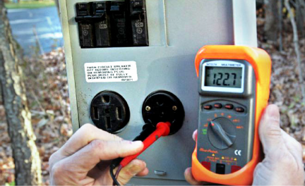
A polarity check for extension cords involves verifying the correct wiring of the cord's plug and socket to ensure that the live and neutral wires are connected properly. The following steps are generally involved in performing a polarity check:
- Turn off the power to the extension cord and unplug it from the power source.
- Use a multimeter or a plug-in polarity tester to check the wiring of the plug and socket.
The tester should indicate that the live wire is connected to the correct pin on the plug and socket, and the neutral wire is connected to the correct pin on the plug and socket. If they are the wrong way around, the switch and fuse are in the neutral leg, which means that the appliance is live even when switched off and if a fault developed on the appliance, the fuse would not blow posing a risk of electric shock or fire.
Check - polarity of the plug top (earth, phase, neutral in a clockwise direction when viewed from the back of a single-phase plug-top) and socket.
Watch this brief video demonstrating how to test and tag extension leads using a portable appliance testing (PAT) machine.
How to test and tag.
Your tutor will also demonstrate the inspection and testing procedures and give you the opportunity to practice these.
Multiphase Cord Test Procedure
The principle of inspection and testing multiphase cords is the same as for single phase cords.
- A visual inspection looking for any obvious defects; damage or deformation of the casing; inadequate cord grip on the plug cover; loose plug pins; etc.
- Electrical testing ensures the continuity resistance of the earth conductor is less than 1Ω; the insulation resistance between all conductors and conductors and earth is greater than 1MΩ and the polarity of the three-phase plug top (earth, L1, L2, L3 and neutral where it exists) is correct.
TESTING ELECTRICAL APPLIANCES
The specific requirements for inspection and testing of electrical appliances are outlined in the Electrical (Safety) Regulations 2010 and the New Zealand Standard for In-service safety inspection and testing of electrical equipment (AS/NZS 3760:2010).
The following steps are recommended for inspecting and testing electrical appliances in New Zealand:
- Visual inspection: A visual inspection should be performed to check for any signs of damage or wear and tear, such as frayed cords, broken plugs, or damaged casings.
- Electrical testing: Electrical testing should be performed using a Portable Appliance Tester (PAT) to ensure the appliance is functioning correctly and is electrically safe. This testing should include earth continuity, insulation resistance, and leakage current tests.
- Tagging and recording: Once the appliance has been inspected and tested, it should be labelled with a tag that includes the date of testing, the next testing due date, and the name of the person who performed the testing. The testing results should also be recorded in a register or database.
- Re-testing: The appliance should be re-tested at regular intervals, as specified in AS/NZS 3760:2010 or according to the manufacturer's instructions.
Specific testing requirements and frequency vary depending on the type of electrical appliance and its intended use.
Class I Appliances
Class I appliances are electrical appliances that are designed to be grounded or earthed. These appliances have exposed metal parts that require a ground connection for safety. The testing requirements include:
- Visual inspection: The appliance should be checked for any visible damage, such as cracks or frayed cords.
- Earth continuity test: The appliance should be tested to ensure that the earth connection is intact and has low resistance.
- Insulation resistance test: The appliance should be tested to ensure that the insulation between the live parts and the earth is adequate.
- Polarity test: The appliance should be tested to ensure that the active and neutral connections are correctly wired.
- Leakage current test: The appliance should be tested to ensure that the leakage current is within safe limits.
Class II Appliances
Class II appliances are those with double insulation or reinforced insulation to provide additional protection against electric shock. Even though they have fewer conductive parts than Class I appliances, they still require the same level of diligence when it comes to inspection and testing.
The specific requirements for inspection and testing of Class II appliances may vary depending on the type of appliance and its intended use, but typically include:
- Visual inspection: To check the condition of the appliance and its components, including the power cord, plug, and casing. It is often necessary to protect cable entry against wear and tear by using strain relief moulding as well as a cord grip clamp on the sheathing of the cord.
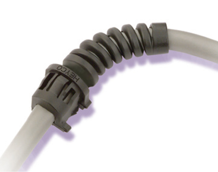
https://www.heyco.com/Strain_Relief_Bushings/img/4-12_114.jpg
- Electrical testing: Electrical testing should be carried out to ensure that the appliance is operating within safe limits. This may include testing for earth continuity, insulation resistance, and polarity. A leakage test should be done on appliances with internal switching that is only activated when the equipment is powered at operating voltage. For equipment that does not have internal switching, then a 500V insulation test is an acceptable alternative.
- Functional testing: Functional testing should be carried out to ensure that the appliance is operating as intended and that all safety features are working correctly. This may include testing the operation of switches, temperature controls, and other features.
- Tagging and recording: Once the inspection and testing have been completed, the appliance should be tagged and recorded to indicate that it has been tested and deemed safe for use. The tag should include the date of testing, the name of the person who carried out the testing, and any other relevant information.
According to AS/NZS 3000:2018 Electrical Installations, Section 5.4.1.3, electrical equipment must be earthed by one of the following methods:
- Connection to a protective earth (PE) conductor in the supply circuit.
- Connection to a local earth electrode, such as a grounding rod.
- Connection to a common earth point that is connected to the supply PE conductor or local earth electrode.
- Double insulation, which eliminates the need for an earth connection.
Earthing of the electrical equipment is not required for:
- Double-insulated equipment with two layers of insulation to provide protection against electric shock.
- Safety Extra Low Voltage (SELV) and Protective Extra Low Voltage (PELV) equipment designed to operate at very low voltages (typically less than 50 V AC or 120 V DC), which eliminates the risk of electric shock.
- Portable equipment that is not connected to a fixed electrical installation however, it must be designed and maintained to ensure that there is no risk of electric shock.
- Class III equipment designed to operate at extra-low voltages (less than 25 V AC or 60 V DC) and also known as a Safety Extra Low Voltage (SELV) circuit.
Residual Current Devices
Residual Current Devices (RCDs) are required to undergo regular inspections and testing to ensure their continued effectiveness. The specific requirements for inspection and testing of RCDs may vary depending on the jurisdiction and the type of RCD, but some general guidelines are:
- Visual inspection – replace your RCD if there are any signs of damage.
- Operating current ≤ 30mA.
- Earth continuity test.
- Insulation /Leakage test.
- Trip Time Test – performed at intervals specified in Table 4 AS/NZS 3760:2010. Either press the test button (and check that the power switches off) or use an RCD Tester to check the trip current and trip time. In New Zealand & Australia AS/NZS3760 requires only an AC test to be done.
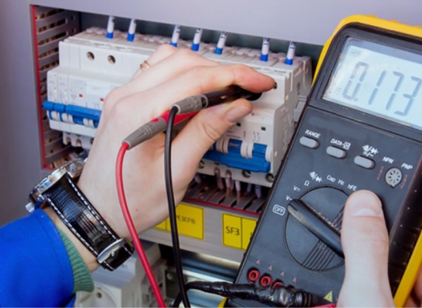
https://www.bmselectrical.com.au/images/services-compliance.jpg
Self-directed Learning
Scenario
- What are the key steps the site manager must take to ensure compliance with the regulations for inspecting and testing electrical equipment? Post your ideas on the class forum page.
Note - The New Zealand Electrical Code of Practice for Electrical Safe Work (NZECP 50:2010) provides guidelines for electrical safety in the workplace, including inspection and testing of electrical equipment.

What we're covering:
- types of support systems
- selection and installation requirements
- moisture and fire barrier ratings
There are several common electrical cable support systems used in New Zealand and Australia. These include:
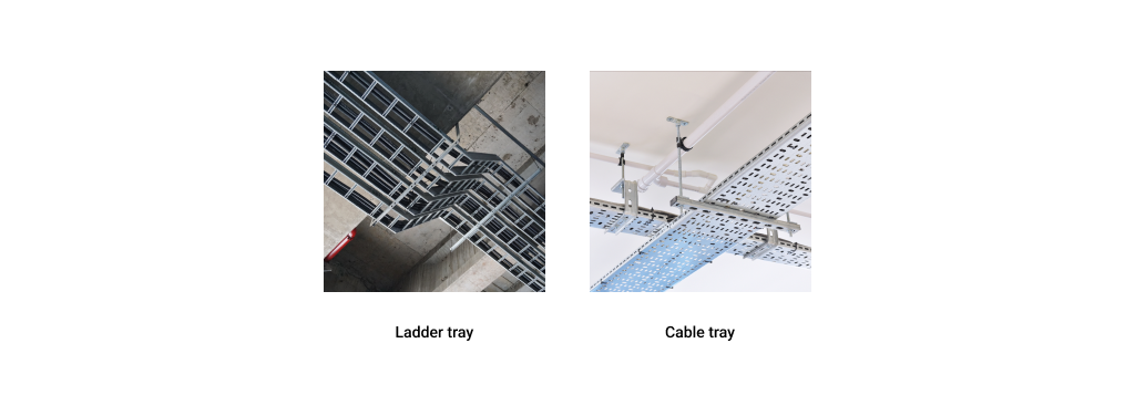
Cable trays: These are metal (galvanised steel, stainless steel or aluminium), or plastic trays used to support and protect cables. Cable trays come in a variety of sizes and can be used in many different types of installations – especially if changes to a wiring system are likely. It is much easier to install new cables in a tray than to pull them through conduit.

Solid-bottom cable trays offer more protection to cables than ventilated trays but in order for cables to enter or exit the tray they must either be cut, or fittings must be used.
What are some situations where you might choose ventilated cable trays rather than solid bottom?
- areas where dust is an issue
- to allow free flow of air to reduce heat and moisture
- to allow multiple exit points for the cables through the top or bottom of the tray
- easy installation and access for small cables
Conduit: Electrical conduits are metal, plastic, or fibre pipes designed to protect and route electrical wiring. It is often made of metal or plastic and comes in different sizes depending on the application. Rigid conduit is most commonly used however flexible conduit is ideal for the last few metres of wiring, where conventional conduit systems are difficult to maneuver and terminate.
AS/NZS 3000 requires insulated, unsheathed cables to be enclosed in a wiring enclosure such as conduit or ducts throughout their entire length.
Long runs of conduit require additional support to keep them from sagging or breaking under their own weight. Straps are used to mount the conduit to ceilings or walls using a screws or bolts. To fasten conduit runs to fixed structures, the conduit is supported using clamps.

What is the difference between conduit and duct?
Used for above ground cables and inside buildings
Used for protection of underground cables
Cable ladders: Also referred to as a ladder tray or cable runway; cable ladders are like cable trays but have a more robust design. They are typically made of metal and are used to support heavier cables and wiring.
Cable trays with covers: Like cable trays, these systems have a cover that provides additional protection to the cables against UV, dust, snow/ice and vandalism.

Catenary wire: ‘Catenary’ describes the shape of the curve formed by a freely hanging wire between two points. A catenary system has come to mean a method of support for cable in which cable is spread from one point to another by means of hanging it between two points through a catenary wire. The electric cable is attached to the catenary wire with cable ties or straps. A catenary wire rope is usually made from galvanised steel wire which can be PVC-coated, or it can be made from stainless steel wire. A high strength-to-weight ratio ensures it can support the load and any mechanical stresses. It should be mounted at sufficient height to prevent danger to those below.
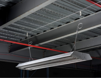
blog.nvent.com/catenary-ideal-for-hanging-in-large-structures/
Refer to AS/NZS 3000:2007 Clause 3.13 for details of cables that can be supported by catenary; requirements of a catenary support; and details of clearances.
Cable trunking: This is a plastic or metal channel used to hide and protect cables. It is often used in offices and homes to conceal electrical wiring.
Cable clips: These are plastic or metal clips used to secure cables to walls or other surfaces. They are typically used in smaller installations.
Cable cleats: Cable cleats are used to secure cables to walls or other surfaces in high-vibration environments, such as in industrial or mining applications.
The specific types of electrical cable support systems used will vary depending on the location, application, and industry.
Exercise 29
Download the worksheet and answer the questions on cable support systems.
CABLE SUPPORT SYSTEM SELECTION REQUIREMENTS:
Load capacity: The cable support system should be able to support the weight of the cables and any additional equipment that may be attached to it.
Material: The material used for the cable support system should be appropriate for the environment in which it will be installed. For example, if the system will be installed in a corrosive environment, a material that is resistant to corrosion should be used.
Size: The size of the cable support system should be appropriate for the cables it will be supporting. The system should be large enough to allow for any necessary future expansion.
Fire rating: The cable support system should have a suitable fire rating to prevent the spread of fire in the event of an electrical fault.
CABLE SUPPORT SYSTEM INSTALLATION REQUIREMENTS:
Location: The cable support system should be installed in a location that is easily accessible for maintenance and inspection.
Height: The height at which the cable support system is installed should be appropriate for the type of cables it will be supporting. The system should be installed at a height that allows for safe and easy access.
Support spacing: The spacing between supports should be appropriate for the weight of the cables and any additional equipment that may be attached to the system.
Fixing: The cable support system should be securely fixed to the structure it is attached to using appropriate fixings.
Cable protection: The cable support system should provide adequate protection for the cables it supports, preventing damage from external factors such as water, heat, or mechanical stress.
Earthing: The cable support system should be earthed to prevent the build-up of static electricity, which can be a safety hazard
Labelling: The cable support system should be clearly labelled to indicate the type of cables it supports and any relevant information about the system.
As previously mentioned, extra low voltage cables must not be installed near low voltage cabling.
Where cables are installed in parallel, steps should be taken to reduce the effects of mutual inductance.
| To reduce unwanted inductance between 3-phase conductors in parallel |  |
|---|---|
|
 |
|
 |
It is important to consult relevant codes and standards, to ensure compliance with all applicable regulations and best practices when selecting and installing electrical cable support systems in New Zealand.
MOISTURE AND FIRE BARRIER RATINGS
Moisture and fire barrier ratings for electric cable penetrations are important to ensure safety and protection of buildings from potential damage caused by fire or water. The general principles for these ratings in New Zealand and Australia are as follows:
Moisture Barrier Ratings: Moisture barrier ratings are used to prevent water or moisture from penetrating electrical cable penetrations. As mentioned previously, the IP (Ingress Protection) rating system is used in NZ. A typical moisture barrier rating for electrical cable penetrations would be IP67, which means that the penetration is completely protected from dust and water.
Fire Barrier Ratings: Fire barrier ratings are used to prevent the spread of fire through electrical cable penetrations. The Fire Resistance Level (FRL) rating system indicates the level of fire resistance of a particular material or structure. The FRL rating system is a combination of three components:
- Structural adequacy (load-bearing capacity).
- Integrity (ability to prevent fire spread).
- Insulation (ability to prevent the transmission of heat).
A typical fire barrier rating for electrical cable penetrations would be FRL60/60/60, which means that the penetration can withstand a fire for 60 minutes without losing its structural integrity, integrity of the seal, or insulation. An FRL of 120/60/60 means the building element has a load-bearing capacity for 120 minutes and can prevent the spread of fire and prevent the transmission of heat for 60 minutes.
In general, the FRL rating of an electrical installation will depend on the type of installation and its location within the building. For example, electrical wiring and equipment installed in a fire-rated compartment, or a fire-resistant wall will need to have a higher FRL rating than those that located in an open space.
Compliance: All electrical cable penetrations comply with the relevant national standards and codes. For example, in New Zealand, the Building Code requires that all electrical cable penetrations meet the standards set out in NZS 4219:2009, which outlines the requirements for fire safety in buildings. The Code specifies minimum FRL ratings for different building elements, including electrical installations. For example, the Building Code requires electrical cables and wires to have a minimum FRL rating of 30/30/30 when they are installed in fire-rated walls or floors. This means that the electrical cables and wires should be able to resist fire for at least 30 minutes in terms of structural adequacy, insulation, and integrity.
AS/NZS 3000 1.5.12 outlines the protection to be provided against fire initiated or propagated by components electrical installation. AS/NZS 3000 3.9.9 and Appendix E also cover the selection of appropriate materials and installation methods to minimise the spread of fire.
Installation: It is important to ensure that all electrical cable penetrations are installed correctly and according to the manufacturer's instructions. This may involve the use of appropriate fire-resistant materials, such as firestop sealants, collars, or pillows, to ensure that the penetration is adequately sealed and can withstand the required fire rating.
Electrical systems can be a significant source of ignition for fires. Faulty wiring, overloaded circuits, and other electrical hazards can all increase the risk of a fire breaking out.
Active fire protection and passive fire protection are two different approaches to managing the risk of fire in buildings. While both are important in ensuring the safety of occupants and limiting property damage, they differ in terms of their function and operation.
Active fire protection systems are designed to detect and suppress fires quickly, often before they have a chance to grow into a larger blaze. Examples of active fire protection systems include fire alarms, smoke detectors, fire sprinklers, and fire extinguishers. These systems require regular maintenance and testing to ensure they are functioning properly. They are usually activated automatically in response to a fire or manually by building occupants.
Passive fire protection, on the other hand, is designed to contain the spread of fire and smoke within a building, limiting damage and allowing occupants to evacuate safely. Passive fire protection measures include fire-resistant building materials such as fire-rated walls, doors, and windows, as well as firestops, fire dampers, and fire-resistant coatings. These measures do not require any active intervention and are intended to work even in the absence of power or human intervention.
When electrical or communication cables are installed through a fire wall or floor, steps must be taken to maintain the fire rating of the structure.
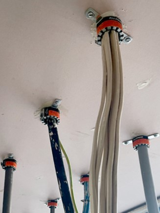
AS/NZS 3000 3.9.9.3 describes the requirements for cables passing through elements of building construction that are required to be fire-rated.
When installing wiring, it is important to identify any wall, floor or roofing material that may form part of a fire cell structure.
Self-directed Learning
The questions for this can be found on the worksheet you downloaded for Exercise 29. Email your answers to your tutor.