Week 5
| Day One | Day Two | Day Three | Day Four | |
|---|---|---|---|---|
| Course Content | Damp situations. AS/NZS 3000:2018 Section 6. Zones, electrical protection, IP ratings & equipotential bonding. | Task - designing a bathroom electrical layout that adheres to safety regulations and zoning guidelines. | Decommissioning electrical fittings and equipment. Isolation. Safe decommission. Decommissioning Steps. | Recommissioning electrical fittings and equipment. |
| Self-directed Learning | Answer questions set from lesson. | Complete design and post to class forum. | Decommissioning Task – battery-operated emergency light fixture. | Matching isolation methods to descriptions. |
In order for you to gain the most value from your qualification and to prepare you for your assessment and the industry, make sure you complete all of the SDL tasks.

What we're covering:
- Damp situations.
AS/NZS 3000:2018 Section 6.
Zones, electrical protection, IP ratings and equipotential bonding
In Modules 4 and 5 you learnt about IP ratings and some of the legal requirements around the choice and placement of electrical equipment and fittings in damp zones.
Electrical installations in damp or wet environments present unique safety challenges due to the increased risk of electric shock and equipment damage. Section 6 of the AS/NZS 3000:2018 outlines the minimum criteria for choosing and installing electrical equipment in areas prone to the impact of water or elevated humidity levels (damp conditions). In the standards you will find guidance on:
Proper Wiring and Installation
Use wiring and cables specifically designed and constructed for damp locations, such as those with moisture-resistant insulation and corrosion-resistant conductors. Seal cable entry points to prevent water penetration.
Exercise 22
Enclosures and Covers
Install weatherproof enclosures and covers for electrical devices, outlets, switches, and junction boxes to shield them from moisture.
Ensure that covers have effective seals or gaskets to maintain watertightness.
Elevated Installations
Elevate electrical components above potential water sources, such as outlets in basements, to prevent water contact and damage.
Exercise 23
Sealant and Insulation
Apply appropriate sealants and insulation around electrical boxes, conduits, and cable entry points to create a barrier against moisture infiltration.
Bathroom and Kitchen Considerations
Install electrical outlets with RCDs in bathrooms, kitchens, and other areas with water sources. Keep electrical devices away from sinks, bathtubs, and showers to avoid splashing.
Ventilation and Drainage
Ensure adequate ventilation to prevent condensation and moisture build-up.
Ensure effective drainage systems to prevent water accumulation near electrical installations.
Equipment Selection
Choose electrical devices, fixtures, and appliances rated for damp or wet locations to prevent malfunction or corrosion.
Exercise 24
Regular Inspection and Maintenance
Conduct routine inspections to identify signs of moisture damage, such as rust, corrosion, or degraded insulation.
Perform maintenance promptly to address any issues and ensure ongoing safety.
Classification of zones
During earlier courses you also came across the concept of Zones (0, 1, 2 and 3) to classify areas within damp spaces.
Watch this video explaining bathroom zones.
In AS/NZS 3000:2018, zones are defined within damp areas like bathrooms to regulate the installation of electrical fittings based on proximity to water sources and the likelihood of moisture exposure. These zones are connected to Ingress Protection (IP) ratings, which ensure appropriate protection against water.
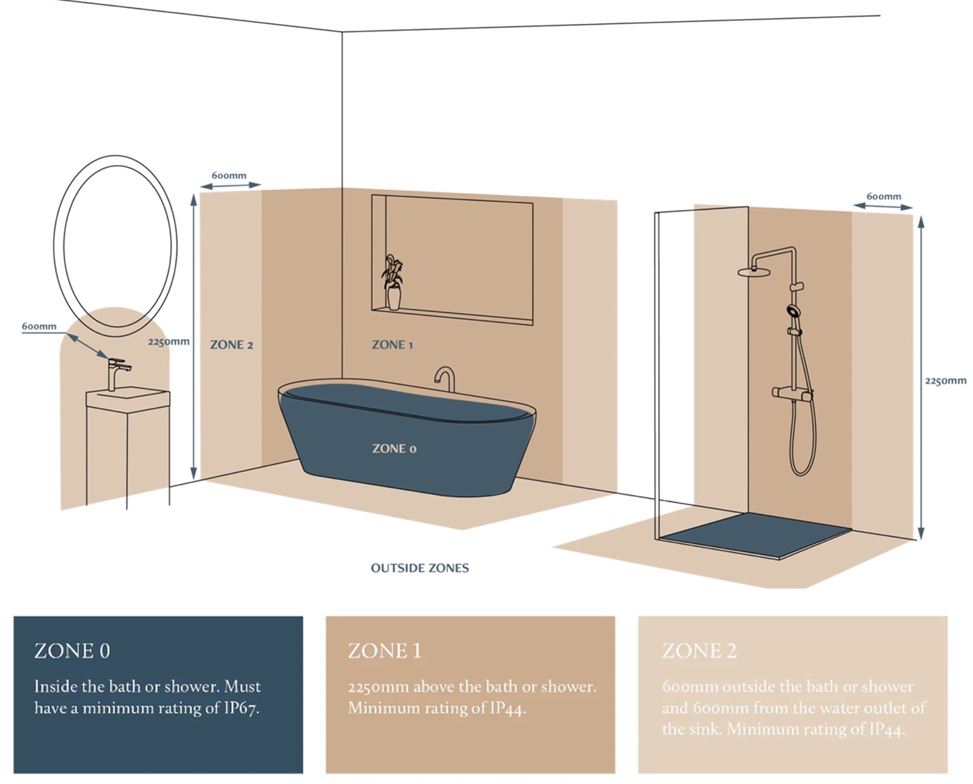
The zones are as follows:
- Zone 0: This zone covers the interior of a bath or shower base. Fittings here must be Low Voltage (SELV) with a maximum of 12V. The minimum IP rating is IPX7 (IP67).
- Zone 1: Directly above the bath or shower up to 2.25m from the floor (or the ceiling if lower), with sealed light fittings requiring a minimum IPX4 (IP44) rating. (IPX5 for communal baths/showers.) Specific dimensions apply for baths, baths with showers, and standalone showers.
- Zone 2: Stretching 0.6m outside the bath or shower, this zone extends 2.25m from the floor. Additionally, it includes the area 600mm from the sink tap. All light fittings here must be sealed with an IPX4 rating. (IPX5 for communal baths/showers.)
- Zone 3: This area lies outside Zone 2, and no specific IP rating is mandated, except in communal baths/showers which must be IPX5 rated. It covers the space between external vertical planes and extends 2.4m from Zone 2's boundary.
Note - The zones do not extend beyond the boundaries of the room.
The zoning system, coupled with IP ratings, ensures the appropriate protection of electrical fittings against water and moisture exposure in different areas of damp environments.
Electrical protection and ingress protection
Electrical protection and IP (Ingress Protection) ratings play a crucial role in ensuring the safety and performance of electrical fittings and equipment, especially in damp or wet environments. These ratings help consumers and professionals make informed decisions about the suitability of electrical products for specific conditions.
Types of electrical protection
Double Insulation (Class II)
Double insulation is a protective measure where the device or equipment has two layers of insulating material. This design prevents the exposure of live parts to users and provides an extra layer of protection against electric shock. Devices with this protection are often marked with a symbol consisting of two squares, one inside the other.
RCDs
RCDs are designed to quickly disconnect the power supply when a leakage current is detected. They offer enhanced protection against electric shock in damp conditions by detecting imbalances between incoming and outgoing currents.
Exercise 25
Provide a summary of the use of RCDs in relation to the installation of socket outlets in different zones according to AS/NZS 3000:2018. Email your tutor when you have completed it.
IP ratings
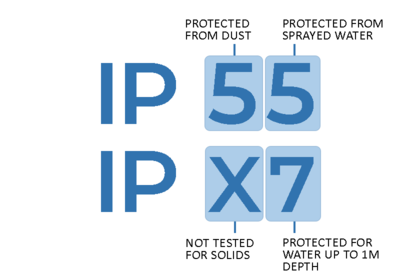
IP ratings indicate the degree of protection provided by enclosures of electrical equipment against the intrusion of solid objects (like dust) and liquids (like water). The IP rating is composed of two digits, each representing a specific level of protection:
- The first digit ranges from 0 to 6 and indicates protection against solid objects.
- The second digit ranges from 0 to 9 and indicates protection against liquids.
IP Ratings for Damp Situations
For electrical fittings and equipment suitable for use in damp situations, you should look for IP ratings that offer adequate protection against moisture.
Here are some common IP ratings that you might encounter.
- IPX4 - This rating indicates protection against splashing water from any direction. It's suitable for damp environments where water might be present due to condensation or light splashing.
- IPX5 - This rating offers protection against water jets from any direction. It's suitable for areas where more substantial water exposure is expected, such as from high-pressure cleaning.
- IPX6 - This rating provides protection against powerful water jets and is suitable for harsher wet conditions.
- IPX7 - This rating indicates protection against temporary immersion in water up to 1 meter for a specified duration. It's suitable for environments where the equipment might be submerged briefly.
- IPX8 - This rating offers protection against continuous immersion in water under conditions specified by the manufacturer. It's suitable for equipment that needs to be submerged for extended periods.
Equipotential bonding for damp areas
Equipotential bonding, as described in Section 5.6.1 of AS/NZS 3000, is a fundamental safety practice in damp areas, aimed at reducing risks arising from voltage differences among exposed conductive components of electrical equipment and other conductive elements. In simpler terms, when you touch a faulty electrical device (such as a dishwasher) and also come into contact with non-electrical metal in a damp setting, the voltages may not be the same. Without proper equipotential bonding, this discrepancy could lead the voltage to flow through you to reach the ground!
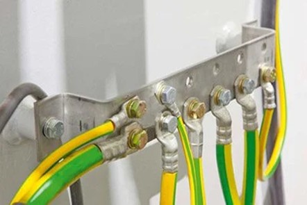
The term "equipotential" literally means equalizing electrical potentials. Conductive parts are interconnected to balance out their potentials, thereby enhancing safety. Bonding typically involves an earth wire establishing secure contact with exposed extraneous conductive parts. This wire is usually connected directly to the main earth bar of the main switchboard and subsequently to the earth electrode.
Bonding conductors are typically 4mm2 in cross-section area with green/yellow insulation and are a normal part of an electrical installation. Their use and application are outlined in the AS/NZS3000:2018.
Examples Of Equipment Requiring Equipotential Bonding
Conductive metal pipes that carry water (including taps) and metal surfaces like sinks. Not necessary when pipes are insulated by non-conductors (plastic pipes) from the earth mass.
Other conductive piping lacking alternative grounding methods and related exposed conductive surfaces.
Concrete reinforcement forming floors or walls in rooms with showers or baths, as well as the shell and enclosure of swimming or spa pools.
Self-directed Learning
Test yourself by completing this quiz based on today’s learning. Download the worksheet here.

What we're covering:
- Task - designing a bathroom electrical layout that adheres to safety regulations and zoning guidelines.
This lesson continues looking at electrical installations in wet or damp areas.
Exercise 26
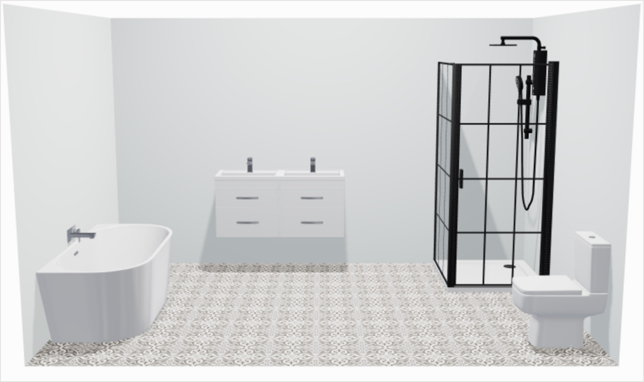
You can complete the following exercise on this worksheet. There is a 3D picture at the end of the worksheet for you to draw on.
Apply the AS/NZS 3000 standard to design a bathroom electrical layout that adheres to safety regulations and zoning guidelines.
- Refer to the regulations and requirements for electrical installations in bathrooms according to AS/NZS 3000. Familiarise yourself with the different zones in a bathroom and the safety measures associated with each zone.
- Examine the 3D bathroom layout provided, noting any potential hazards or considerations related to water sources and wet areas. Potential hazards include…
- Divide the bathroom layout into different zones according to the regulations. Shade each zone a different colour and write in its dimensions (these do not have to be to scale).
- Plan and strategically place (draw) electrical installations within each zone, while adhering to the regulations. Consider safety, convenience, and the overall layout of the bathroom. These electrical installations should include:
- Power sockets - Show the placement of power sockets in accordance with zone requirements, e.g., you might include power sockets near vanities and countertops, following the specified distances from water sources.
- Light switches - Indicate the location of light switches, considering convenience and safety. Make sure switches are appropriately positioned to avoid contact with wet hands.
- Heated towel rail - Show the position of a heated towel rail, taking into account its distance from water sources and any specific regulations.
- Exhaust fan - Indicate the placement of an exhaust fan, considering proper ventilation and compliance with zoning guidelines.
- Ceiling or wall-mounted light fixtures - Show the placement of ceiling or wall-mounted light fixtures, ensuring they are positioned safely and effectively illuminate the bathroom.
- Shaver outlets - Include shaver outlets in suitable locations, adhering to regulations and safety standards.
- Complete the tables in the worksheet explaining the rationale behind your placement of the electrical installations.
- Share your completed bathroom electrical layout with your tutor and classmates in the class forum, highlighting the zoning, installation placements, and safety considerations based on the AS/NZS 3000 standard.
- Have you followed the AS/NZS 3000 standard? Have your classmates adhered to the standard? Are there any improvements you would make?
This is the picture you will be drawing on:
Self-directed Learning
Complete the exercise. Post to the class forum and provide feedback on other designs.

What we're covering:
- Decommissioning electrical fittings and equipment.
- Isolation.
- Safe decommission.
- Decommissioning Steps.
What does decommission of electrical fittings and systems mean?
Exercise 27
Make a note of some reasons why it may be necessary to decommission electrical fittings or systems. Ask your tutor next time you are on campus.
What is Isolation? Is there a difference between switching off and isolating?
Switching off stops an electrical appliance or circuit from going or working. Isolation separates it from all possible sources of electrical energy for reasons of safety (AS/NZS 3000 1.4.75).
If isolation is for reasons of safety, part of that safety should include making sure that the equipment cannot be re-energised accidentally so that the equipment stays safe to work on.
Exercise 28
Importance of Safe Decommissioning
Safe decommissioning of electrical fittings and systems is crucial for protecting lives, property, the environment, and the overall integrity of electrical installations. It ensures that electrical equipment is taken out of service responsibly and in a manner that minimises risks and hazards.
Key reasons for safe decommissioning include:
- Preventing accidents and injuries: Electrical equipment carries the risk of electric shock, burns, and other injuries. Safe decommissioning ensures that equipment is properly disconnected from power sources, reducing the risk of accidental energization during maintenance or disposal.
- Fire prevention: Faulty or improperly decommissioned electrical equipment can cause short circuits, arcing, and electrical fires. Safe decommissioning helps eliminate potential ignition sources and reduces the risk of fire hazards.
- Compliance with regulations: Regulations and standards govern the proper decommissioning of electrical equipment. Adhering to regulations ensures legal compliance, prevents fines, and demonstrates a commitment to safety.
- Environmental considerations: Safe decommissioning includes proper disposal or recycling of electrical equipment. Incorrect disposal can lead to environmental contamination due to hazardous materials like lead, mercury, or other toxic substances present in some equipment.
- Protection of workers: Electrical professionals and maintenance personnel involved in decommissioning need to be protected from potential hazards. Safe procedures and training minimise the risks they face while carrying out decommissioning tasks.
- Equipment integrity: Incorrect decommissioning can damage equipment or make it unsuitable for future use, resulting in wasted resources and increased costs. Proper decommissioning preserves the equipment's value and potential for reuse.
- Controlling voltage fluctuations: Some electrical equipment, when decommissioned incorrectly, can lead to power quality issues or voltage fluctuations that affect other connected equipment or the entire system.
- Preventing unplanned downtime: Poorly decommissioned equipment may impact the stability and reliability of the entire electrical system, leading to unexpected downtime and disruptions.
- Maintaining record keeping: Safe decommissioning involves documentation of the process, which is valuable for tracking equipment status, maintenance history, and disposal methods. This information aids in audits, future planning, and compliance verification.
- Public safety: Faulty electrical systems pose risks to occupants of buildings or facilities, as well as neighboring properties. Safe decommissioning contributes to overall public safety.
- Long term savings: Properly decommissioning equipment prevents unforeseen incidents that could lead to costly repairs, legal actions, insurance claims, and operational disruptions.
Watch the following videos which emphasize the need for safety when carrying out any decommissioning activity.
- Isolating machinery when not in production
- Arc flash safety film
- How To Safely Remove a Wall Light Fitting
Isolation and Recommissioning Plan
A large-scale isolation or decommissioning project requires a plan. An isolation and recommissioning plan entails a structured approach to ensure the safe and orderly isolation and reactivation of critical plant and equipment. This comprehensive document includes:
- Specific details about the tasks at hand and the authorized personnel assigned to perform them.
- Clearly defined completion dates, along with designated timeframes, contributing to effective project management.
- A well-organised sequence for the recommissioning process, often involving the collaboration of multiple professionals and trades.
- Incorporation of manufacturers' specifications, test results, and specialised testing procedures, which are essential for compliance and accurate reporting.
The Decommissioning Process
Decommissioning simple electrical fittings and equipment involves a series of steps to ensure safety, prevent electrical hazards, and properly remove the equipment from service.
Here's a step-by-step process for safely decommissioning such items:
- Turn off the power: Before starting any work, ensure the power supply to the electrical fitting or equipment is completely turned off. This may involve switching off the circuit breaker or unplugging the equipment from the power source.
- Use proper PPE: Wear appropriate PPE, such as insulated gloves, safety goggles, and non-conductive footwear, to protect yourself from potential electrical hazards.
- Isolate from power source: If applicable, unplug the equipment from the power source. If the equipment is hardwired, isolate it by turning off the circuit breaker and locking/tagging it to prevent accidental re-energization.
- Inspect for visible damage: Carefully examine the equipment for any visible signs of damage, such as frayed cords, exposed wires, or burn marks. Do not proceed if there is damage that could pose a safety risk.
- Disconnect wires and components: If the equipment has detachable wires or components, disconnect them according to manufacturer guidelines. Take note of their positions and connections for reassembly if necessary.
- Cap or insulate wires: If there are exposed wires, cap them with wire nuts or insulate them using electrical tape to prevent accidental contact or short circuits.
- Remove batteries: for battery-operated equipment, remove the batteries and safely dispose of them according to local regulations.
- Dispose of waste properly: Dispose of any removed components, wires, or batteries in accordance with local waste disposal guidelines. Hazardous materials should be handled as directed.
- Secure or label equipment: If the equipment is being stored or transferred, secure it in a safe location or label it as "out of service" to prevent unintended use.
- Document decommissioning: Keep records of the decommissioning process, including dates, actions taken, and the responsible individuals. This documentation can be useful for future reference.
- Notify relevant parties: If required, inform relevant parties, such as maintenance personnel or supervisors, about the decommissioning to ensure proper communication and coordination.
- Follow manufacturer’s guidelines: Always follow the manufacturer's instructions for decommissioning specific equipment. Manufacturer guidelines may provide additional safety measures or recommendations.
- Re-evaluate power source: Double-check that the power source remains turned off before leaving the decommissioned equipment or area.
- Secure the area: If the decommissioned equipment will be left in place temporarily, secure the area to prevent unauthorised access and clearly mark the equipment as "not in use”.
- Final inspection: Conduct a final visual inspection of the area to ensure all necessary steps have been taken and decommissioned equipment is safe and properly secured.
Exercise 29
Self-directed Learning
You are tasked with decommissioning a battery-operated emergency light fixture. What steps should you take to ensure its safe removal and disposal?

What we're covering:
- Recommissioning electrical fittings and equipment.
Let’s recap the decommissioning process before we proceed to recommissioning.
Exercise 30
This exercise requires you to demonstrate your understanding of the procedures for disconnecting conductors at an electrical appliance or connection unit terminating points. You should describe each step of the disconnection process, including safety measures and precautions.
Instructions
Read the list of procedures for disconnecting conductors at an electrical appliance or connection unit terminating points below.
Procedures
- Attaching safety tags.
- Isolation methods.
- Checking isolation (“prove – test – prove”).
- Securing isolation (lock off).
- Identification of conductors and terminals as disconnection proceeds.
- Making all exposed conductor ends safe.
- Ensuring disconnected cables are protected from mechanical damage or interference.
For each procedure provide a detailed description of the:
- Action.
- Safety measure(s).
- Reason(s) for each step.
Recommisioning electrical fittings and equipment
After completing repairs or maintenance, it's time to recommission electrical fittings and systems. Before powering them up again, it's crucial to run safety tests to make sure they are safe, operational, and compliant with relevant regulations and standards.
When recommissioning machines and equipment, it's important to follow the testing steps recommended by the manufacturer. These tests ensure that everything works as it should. Also, the equipment needs to meet current regulations, like the electrical guidelines in AS/NZS 3000 and AS/NZS 3760 for appliances. The tests need to match the processes and expected results outlined in these standards.
Exercise 31
Can you list ten scenarios where you might be required to recommission electrical fittings or systems?
Self-directed Learning