A 'network' can be defined as a group or system of interconnected people. For example, power is delivered to your house via an electricity network, consisting of power plants, power lines, substations and local connections.
You likely have a social network of friends, family and co-workers.
Airlines connect cities and countries by flying common routes between connecting airport networks.
A computer network is a system of interconnected devices (computers, servers, routers) that enable communication and resources sharing.
Computer network components include the major parts needed to install a network both at the office and home level. Before delving into the installation process, you should be familiar with each part so that you can choose and buy the right component that fits with your network system.
These hardware components include cable, Hub, Switch, NIC (Network Interface Card or 'network card'), modem and router. Depending on the type of network you will install, some of the parts can be eliminated. For example, in a wireless network, you do not need cables, hubs, etc.
A computer network is a group of 2 or more computers that connect to share a resource. Sharing of devices and resources is the purpose of a computer network. You can share printers, fax machines, scanners, network connections, local drives, copiers and other resources.
In computer network technology, networks range from simple to complex levels; however, the required devices and rules (protocols) are mostly the same.
Major computer network hardware components
Link/form computers into a computer network using the following devices (some are optional):
- Network Interface Card
- hub
- switches
- router
- cables and connectors
- modem.
Network Interface Card

A network interface card is a device that enables a computer to talk with another computer/network. Using unique hardware addresses (MAC addresses) encoded on the card chip, the data-link protocol employs these addresses to discover other systems on the network to transfer data to the correct destination.
There are 2 types of network cards: wired and wireless.
The wired NIC uses cables and connectors as a medium to transfer data, whereas, in the wireless card, the connection is made using an antenna that employs radio wave technology. All modern laptop computers incorporate wireless NIC in addition to the wired adapter.
Network Card Speed
A Network Interface Card, one of the main computer network components, comes with different speeds: 10Mbps, 100Mbps, 1000Mbps and so on. Recent standard network cards are built with Gigabit (1000Mbps) connection speed. They also support connecting slower speeds such as 10Mbps and 100Mbps. However, the speed of the card depends on your LAN speed.
For example, if you have a switch that supports up to 100Mbps, your NIC will also transfer data with this same speed even though your computer NIC has still the capability to transfer data at 1000Mbps (1Gbps). In modern computers, the network adapter is integrated with a computer motherboard. However, if you want an advanced and fast Ethernet card, you may buy and install it on your computer using the PCI slot found on the motherboard (desktop) or Express Card slots on the laptop.
Hub
A 'hub' is a device that splits a network connection into multiple computers--it is like a distribution centre.
When a computer requests information from a network or a specific computer, it sends the request to the hub through a cable. The hub will receive the request and transmit it to the entire network. Each computer in the network should then figure out whether the broadcast data is for them or not.
Hubs are becoming obsolete and replaced by more advanced communication devices such as switches and routers.

Switch
The switch is a telecommunication device grouped as one of the computer network components. The switch is like a hub, but built-in with advanced features. It uses physical device addresses in each incoming message to deliver the message to the correct destination or port.
Like the hub, the switch doesn’t broadcast the received message to the entire network; rather, it checks which system or ports that the message should be sent to (i.e. the switch connects the source and destination directly, which increases the network's speed).
Both switch and hub have common features: multiple RJ-45 ports, power supply and connection lights.
Cables and connectors
Cable is a form of transmission media that can transmit communication signals. The wired network topology uses a special type of cable to connect computers to a network.
There are some solid transmission media types (which are listed below).
Cable is classified as Category 1, 2, 3, 4, 5, 5E, 6 and 7. Category 5E, 6 and 7 are high-speed cables that transmit 1Gbps or more.

Router
When we talk about computer network components, the other device used to connect a LAN with an internet connection is called a 'router'. When you have 2 distinct networks (LANs) or want to share a single internet connection to multiple computers, we use a router.
In most cases, current routers also include a switch that can be used as a switch; in other words, you don’t need to buy both switch and router, particularly when installing small business and home networks.
There are 2 types of routers: wired and wireless. The choice depends on your physical office/home setting, speed and cost.
Modem
A modem enables you to connect your computer to the available internet connection over the existing telephone line. Like NIC, a modem is not integrated with a computer motherboard. It comes as a separate part installed on the PCI slots found on the motherboard.
A modem is not necessary for LAN, but is required for internet connection options such as dial-up and DSL.
Some modems differ in speed and transmission rate. The following are some examples:
- standard PC modems or dial-up modems (56Kb data transmission speed)
- cellular modem (used in a laptop that enables to connect while on the go),
- cable modem (500 times faster than standard modem)
- DSL (Digital Subscriber Line) Modems are the most popular.
Whether you want to install a network at your office or home, these are the required computer network components. Depending on your situation, some of the devices can be disregarded (e.g. a router is suitable for a home network as it also bundles a switch).
In computing, a network usually consists of 2 or more computer systems connected either physically or wirelessly, enabling them to share files and folders, print, send and receive emails, and access shared databases and applications.
When talking about networks, we often refer to either a 'local area network' (LAN) or a 'wide area network' (WAN).
Network cabling
Cable is the medium through which information usually moves from one network device to another.
There are several types of cable which are commonly used within LANs. In some cases, a network will utilise only one type of cable; while other networks will use various cable types. The type of cable chosen for a network is related to the network's topology, protocol and size.
Understanding the characteristics of different types of cable and how they relate to other aspects of a network is necessary to develop a successful network.
The information below discusses the cables used in networks (and other related topics):
- Unshielded Twisted Pair (UTP) cable
- Shielded Twisted Pair (STP) cable
- Coaxial cable
- Fibre Optic cable
- Cable Installation cuides
- Wireless LANs
- Unshielded Twisted Pair (UTP) cable.
Twisted pair cabling comes in 2 varieties: shielded and unshielded. Unshielded twisted pair (UTP) is the most popular and is generally the best option for school networks.

The quality of UTP may vary from telephone-grade wire to extremely high-speed cable.
The cable has 4 pairs of wires inside the jacket: each pair is twisted with a different number of twists per inch to help eliminate interference from adjacent pairs and other electrical devices. The tighter the twisting, the higher the supported transmission rate and the greater the cost per foot.
The EIA/TIA (Electronic Industry Association/Telecommunication Industry Association) has established standards of UTP and rated 6 categories of wire--as shown in the table below (additional categories are emerging).
Categories of Unshielded Twisted Pair
| Category | Speed | Use |
|---|---|---|
| 1 | 1 Mbps | Voice Only (Telephone Wire) |
| 2 | 4 Mbps | LocalTalk & Telephone (Rarely used) |
| 3 | 16 Mbps | 10BaseT Ethernet |
| 4 | 20 Mbps | Token Ring (Rarely used) |
| 5 | 100 Mbps (2 pair) | 100BaseT Ethernet |
| 1,000 Mbps (4 pair) | Gigabit Ethernet | |
| 5e | 1,000 Mbps | Gigabit Ethernet |
| 6 | 10,000 Mbps | Gigabit Ethernet |
Unshielded Twisted Pair Connector
The standard connector for unshielded twisted pair cabling is an RJ-45 connector.
This is a plastic connector that looks like a large telephone-style connector. A slot allows the RJ-45 to be inserted only one way. RJ stands for 'Registered Jack', implying that the connector follows a standard borrowed from the telephone industry. This standard designates which wire goes with each pin inside the connector.

Shielded Twisted Pair (STP) Cable
Although UTP cable is the least expensive cable, it may be susceptible to radio and electrical frequency interference (it should not be too close to electric motors, fluorescent lights, etc.). If you must place cable in environments with lots of potential interference, or if you must place cable in extremely sensitive environments that may be susceptible to the electrical current in the UTP, shielded twisted pair may be the solution.
Shielded cables can also help to extend the maximum distance of the cables.
Shielded twisted pair cable is available in 3 configurations:
- each pair of wires is individually shielded with foil
- with a foil or braid shield inside the jacket covering all wires (as a group)
- there is a shield around each pair and around the entire group of wires (referred to as 'double shield twisted pair').
Coaxial Cable
Coaxial cabling has a single copper conductor at its centre. A plastic layer provides insulation between the centre conductor and a braided metal shield. The metal shield helps to block any outside interference from fluorescent lights, motors and other computers.
Although coaxial cabling is difficult to install, it is highly resistant to signal interference. Also, it can support greater cable lengths between network devices than twisted-pair cables. The 2 types of coaxial cabling are: thick coaxial and thin coaxial.
Thin coaxial cable: is also referred to as 'thinnet'. 10Base2 refers to the specifications for a thin coaxial cable carrying Ethernet signals. The '2' refers to the approximate maximum segment length being 200 metres. The maximum segment length is 185 metres. Coaxial cable has been popular in school networks, especially linear bus networks.
Thick coaxial cable: is also referred to as 'thicknet'. 10Base5 refers to the specifications for thick coaxial cable carrying Ethernet signals. The '5' refers to the maximum segment length being 500 metres. The thick coaxial cable has an extra protective plastic cover that helps keep moisture away from the centre conductor, making thick coaxial a great choice when running longer lengths in a linear bus network.
One disadvantage of thick coaxial is that it does not bend easily and is difficult to install.

Coaxial Cable Connectors
The most common connector used with coaxial cables is the Bayonne-Neill-Concelman (BNC) connector. Different adapters are available for BNC connectors (including a T-connector, barrel connector and terminator).
Connectors on the cable are the weakest points in any network. To help avoid problems with your network, always use the BNC connectors that crimp, rather screw, onto the cable.

Fibre Optic Cable
Fibre optic cabling consists of a centre glass core surrounded by several layers of protective materials. It transmits light rather than electronic signals, eliminating the problem of electrical interference. This makes it ideal for certain environments that contain a large amount of electrical interference.
It has also made it the standard for connecting networks between buildings due to its immunity to the effects of moisture and lighting.
Fibre optic cable can transmit signals over longer distances than coaxial and twisted pairs. It also can carry information at vastly greater speeds. This capacity broadens communication possibilities to include video conferencing and interactive services.
The cost of fibre optic cabling is comparable to copper cabling; however, it is more difficult to install and modify. '10BaseF' refers to the specifications for fibre optic cable carrying Ethernet signals.
The centre core of fibre cables is made from glass or plastic fibres. A plastic coating then cushions the fibre centre, and Kevlar fibres help to strengthen the cables and prevent breakage. The outer insulating jacket is made of Teflon or PVC.
There are 2 common types of fibre cables: single-mode and multimode.
- Multimode cable: has a larger diameter; however, both cables provide high bandwidth at high speeds.
- Single-mode cable: can provide more distance, but it is more expensive.
| Specification | Cable type |
|---|---|
| 10BaseT | Unshielded Twisted Pair |
| 10Base2 | Thin Coaxial |
| 10Base5 | Thick Coaxial |
| 100BaseT | Unshielded Twisted Pair |
| 100BaseFX | Fibre Optic |
| 100BaseBX | Single-mode Fibre |
| 100BaseSX | Multimode Fibre |
| 1000BaseT | Unshielded Twisted Pair |
| 1000BaseFX | Fibre Optic |
| 1000BaseBX | Single-mode Fibre |
| 1000BaseSX | Multimode Fibre |
Cable installation guidelines
When installing or 'running' cable, it is best to follow the simple rules listed below.
- Always use more cable than you need. Leave plenty of slack.
- Test every part of a network as you install it. Even if it is brand new, it may have problems that will be difficult to isolate later.
- Stay at least 3 feet away from fluorescent lightboxes and other sources of electrical interference.
- If it is necessary to run a cable across the floor, cover the cable with cable protectors.
- Label both ends of each cable.
- Use cable ties (not tape) to secure cables in position.
Wireless LANs
More and more networks are operating without cables--in the wireless mode.
Wireless LANs use high-frequency radio signals, infrared light beams or lasers to communicate between the workstations, servers or hubs. Each workstation and file server on a wireless network has some transceiver/antenna to send and receive the data. Information is relayed between transceivers as if they were physically connected.
Wireless communications can also occur through cellular telephone technology, microwave transmission or satellite for longer distances.
Wireless networks are great for allowing laptop computers, portable devices or remote computers to connect to the LAN. Wireless networks are also beneficial in older buildings where it may be difficult--or impossible--to install cables.
The 2 most common types of infrared communications used in schools are line-of-sight and scattered infrared communication broadcast.
- Line-of-sight communication: means that there must be an unblocked direct line between the workstation and the transceiver. If a person walks within the line of sight while there is a transmission, the information would need to be sent again. This kind of obstruction can slow down the wireless network.
- Scattered infrared communication: is a broadcast of infrared transmissions sent out in multiple directions that bounce off walls and ceilings until they eventually hit the receiver.
Networking communications with laser are virtually the same as line-of-sight infrared networks.
Wireless standards and speeds
The Wi-Fi Alliance is a global, non-profit organisation that helps to ensure standards and interoperability for wireless networks, and wireless networks are often referred to as WiFi (Wireless Fidelity).
The original Wi-Fi standard (IEEE 802.11) was adopted in 1997. Since then, many variations have emerged (and will continue to emerge).
Wi-Fi networks use the Ethernet protocol.
| Standard | Max speed | Typical range |
|---|---|---|
| 802.11a | 54 Mbps | 150 feet |
| 802.11b | 11 Mbps | 300 feet |
| 802.11g | 54 Mbps | 300 feet |
| 802.11n | 100 Mbps | 300+ feet |
Wireless Security
Wireless networks are much more susceptible to unauthorised use than cabled networks. Wireless network devices use radio waves to communicate with each other. The greatest vulnerability to the network is that rogue machines can 'eavesdrop' on radio wave communications. Unencrypted information transmitted can be monitored by a third party which, with the right tools, could quickly:
- gain access to your entire network
- steal valuable passwords to local servers and online services
- alter or destroy data
- access personal and confidential information stored in your network servers.
To minimise the possibility of this, all modern access points and devices have configuration options to encrypt transmissions. These encryption methodologies are still evolving, as are the tools used by malicious hackers, so always use the strongest encryption available in your access point and connecting devices.
A note on encryption: As of this writing, WEP (Wired Equivalent Privacy) encryption can be easily hacked with readily-available free tools which circulate the internet. WPA and WPA2 (Wi-Fi Protected Access versions 1 and 2) are much better at protecting information, but using weak passwords or passphrases when enabling these encryptions may allow them to be easily hacked. If your network is running WEP, you must be very careful about using sensitive passwords or other data.
Three basic techniques are used to protect networks from unauthorised wireless use. Use any of these techniques when setting up your wireless access points.
- Encryption: Enable the strongest encryption supported by the devices you will be connecting to the network. Use strong passwords ('strong' passwords are generally defined as: passwords containing symbols, numbers and mixed-case letters, at least 14 characters long).
- Isolation: Use a wireless router that places all wireless connections on a subnet independent of the primary private network. This protects your private network data from pass-through internet traffic.
- Hidden SSID: Every access point has a Service Set Identifier (SSID) that, by default, is broadcast to client devices so that the access point can be found. By disabling this feature, standard client connection software won't 'see' the access point.
Advantages of wireless networks
- Mobility: With a laptop computer or mobile device, access can be available throughout a school, at the mall, on an aeroplane, etc. More and more businesses are also offering free wi-fi access (hot spots).
- Fast setup: If your computer has a wireless adapter, locating a wireless network can be as simple as clicking Connect to a Network. In some cases, you will connect automatically to networks within range.
- Cost: Setting up a wireless network can be much more cost-effective than buying and installing cables.
- Expandability: Adding new computers to a wireless network is as easy as turning the computer on (as long as you do not exceed the maximum number of devices).
Disadvantages of wireless networks
- Security issues: Be careful. Be vigilant. You must proactively protect your sensitive data with backups, isolated private networks, strong encryption and passwords, and monitor network access traffic to and from your wireless network.
- Interference: Because wireless networks use radio signals and similar techniques for transmission, they are susceptible to interference from lights and electronic devices.
- Inconsistent connections: How many times have you heard, 'Wait a minute, I just lost my connection'? Because of the interference caused by electrical devices and items blocking the path of transmission, wireless connections are not nearly as stable as those through a dedicated cable.
- Speed: The transmission speed of wireless networks is improving; however, faster options (such as gigabit Ethernet) are available via cables. Suppose you are only using wireless for internet access--in that case, the actual internet connection for your home or school is generally slower than the wireless network devices, so that connection is the bottleneck. If you are also moving large amounts of data around a private network, a cabled connection will enable that work to proceed much faster.

One of the most important considerations when installing new hardware peripheral is installing the device with the least amount of disruption to the client. A client may not be very happy if you install a piece of hardware equipment while they're creating an urgent report.
It is important to schedule installation times that are:
- also suitable to the client’s or computer user’s schedules
- of a sufficient length to install and thoroughly test the hardware device.
To achieve this, make sure that you are aware of:
- common organisational procedures that regularly need to be performed on the computer (e.g. month-end processing or weekly backups) and plan installations outside these periods
- current projects, deadlines and schedules of the client/user.
Installations should be scheduled for times such as:
- quiet periods (e.g. during holiday periods)
- before or after normal office hours
- while the client/user is out of the office
- when the client will not be needing their computer.
It can be difficult to determine how long it will take to install a peripheral device as installation times will vary according to the type of device, current operating system, problems requiring troubleshooting, and the installer's experience.
If you are regularly performing generic installations, keeping a log noting the timing required and problems experienced could help estimate the time spent on future installations.
Once you have arranged a suitable time, make sure you adhere to it or give advanced notice if you are delayed. Remember that clients may have scheduled their daily workload around the installation.
Also, consider the client's expectation of the timeframe when installing new hardware. If you work for a busy organisation, working out a daily to-do list may be necessary. Order tasks with priority given to installations that perform critical functions or those which have been waiting to be done for the longest amount of time.
Installing and configuring hardware peripherals
Each peripheral device will have its installation procedure with various computer systems, operating systems, peripheral types and features and manufacturer.
It is important to refer to manufacturer guidelines and manuals to ensure that all procedures are correctly followed when installing any hardware device.
Procedures that are generally followed when installing any new peripheral device include:
- plugging in the cables between the device and the computer
- troubleshooting installation when necessary
- installing any drivers
- customising the device
- testing the device for satisfying required conditions.
Driver
Whenever you install a hardware peripheral device, you will also have to install a 'driver'. A driver is a software program that allows the hardware device to talk to the operating system.
Generally, the driver software will be included within the packaging of a new device. Sometimes operating systems (such as Windows XP) automatically provide their drivers if you don’t provide one. At times, it may be necessary to find a newer version of a driver than that which the manufacturer has provided.
It is a good idea to regularly check the manufacturer’s website to see if any new drivers have been developed.
Plug and play
'Plug and play' is a hardware technology that enables many operating systems to recognise new hardware devices automatically/configure them. Most USB devices support plug and play.

Installation of a printer
The following steps are generally those followed during the installation of most printers.
- Obtain the correct printer cable. A printer won’t automatically have a cable included with the original purchase in many cases. Check the printer specifications—you will probably need to buy either a parallel or USB cable.
- Plug in the cable. Turn off the power to both the printer and the computer. Plug the printer cable into the correct port of the computer. Depending on the type of printer, the port will most likely be either a USB or a parallel port located on the back of the computer. If you are plugging the cable into a parallel port connection, you will need to secure the cable by tightening small screws or snapping in wire connectors.
- Install the ink. Depending on your printer, you may need to install an ink cartridge (for inkjet printers) or a toner cartridge (for laser printers). Turn the computer’s power on and follow the manufacturer’s guidelines to install a new cartridge.
- Install the printer driver. The computer will recognise that new hardware has been installed, or you will need to tell the computer that a new device has been added. In either case, you will be asked for the printer model and a printer driver at some stage. Make sure you install the printer driver at this stage. Sometimes the installation CD will automatically run, installing the printer driver simultaneously.
- Print a test page. Often, you will be asked if you would like to print a test page at the end of the driver installation. This is a good idea because you can quickly determine if the printer is working correctly. If not, you can troubleshoot the installation.
- Troubleshoot printer installation (when necessary). If a page cannot print, it is necessary to go back and determine why the printer is not working. There are several factors that can contribute to printer problems, including:
- cables between printer and computer aren't connected properly
- printer driver is not suitable for the current operating system
- paper is loaded incorrectly
- ink cartridge or toner is not correctly installed
- printer power switch is off.
Solutions to some of these issues are suggested below.
Recommended solutions for common printer problems
Problem/Solution(s)
Problem:
A blank page is coming out of the printer
Solution:
- You may have run out of ink or toner. Replace ink cartridge or toner.
- Make sure that your printer has been set to the default setting.
Problem/Solution(s)
Problem:
The document is printing on the wrong part of the page
Solution:
- Check that you have aligned the printer to the correct orientation (portrait or landscape).
- Ensure the margins have been set correctly in the software program you are using (e.g. the word processor or desktop publishing package).
-
Make sure the paper has been loaded correctly
Problem/Solution(s)
Problem:
The quality of the printout is poor
Solution:
- If the printer is an inkjet, the heads of the ink cartridge may need to be cleaned.
- Some printers have software that allows you to change the quality of the printout from 'draft' to 'best quality'.
Customising the printer
Depending on your client’s needs, it may be necessary to alter the default printer settings.
Some settings that may be customised include:
- Page Layout: A page may need to be printed in either landscape or portrait orientation.
- Paper Source: Depending on the complexity of the printer, there may be a variety of paper trays the printer has available to use.
- Print Quality: Depending on the printer use, a client may require the 'best', 'normal' or 'draft' print quality.
- Default Printer: If there is more than one printer attached to a computer, you may need to change the settings so that the newer model is considered the default model.
Installation of a network switch
Network switches for home and small office use are typically stand-alone units, while switches for larger networks are usually rack-mounted. Either way, they typically use either Cat5 or Cat6 ethernet cables. Switches allow multiple computers to connect to a single internet connection, but rather than simply passing the signal through, like a network hub, a switch can manage that network traffic.
Switches differ in how they handle network traffic, but all of them are installed in a very similar way.
- Provide power to the switch, if required. For a stand-alone switch, this simply means plugging in the power supply. For rack-mounted switches, this means using a slot with power supplied to it.
- Connect the incoming network cable to the switch. Although any slot can be used on most network switches, it is a good idea to use the first slot, so anyone can quickly identify the incoming cable. (The incoming cable will be the one coming from your modem for home and small office applications.)
- Connect a Cat5 or Cat6 cable to another slot in the network switch. Connect the other end to a computer you want to be connected to the network.
- Repeat this process until all the computers are connected, or all slots are filled.

Installation of a router
Selecting the Right Router
The heart of your home network is your router, so it's worth investing time in researching your options before deciding on one. (A good place to start is this list of the best wireless routers.)
Depending on your current router's age, you don't necessarily need to upgrade to new hardware. However, if your router is more than a few years old, it may only support WEP for security—if so, upgrade immediately. WEP is no longer secure.
Large ISPs such as Comcast and Verizon typically provide customers with routers instead of modems. Most of these models are less feature-rich than the routers you could purchase yourself.
Getting Online
Now that you have a router, you need to connect it online. If your service provider provided a modem when they activated your internet service, this should be pretty simple. Just follow these steps:
- Turn off your modem.
- Unplug the modem's Ethernet cable from the PC.
- Connect that cable to the WAN or internet port on your new router.
- Power on your modem (wait for a minute or two).
- Next, power on your router (wait for a minute or two).
- Now use another Ethernet cable to connect the PC to your router's LAN port.
- Turn on your PC.
By default, most consumer routers are set up to use DHCP to assign an IP address to your computer automatically so, if everything works, you should now be online.
If you use an ISP-supplied router instead of a modem, things are a bit more complicated. First, you reconfigure the ISP's router to operate in bridge mode before connecting it to your new router.
'Bridge mode' means the old router doesn't do anything to the network traffic and just passes it along to your new router for processing. While you can do this on your own, some providers will do it for you remotely once you make the request.
Once the ISP-supplied router is in bridge mode, follow the steps (provided above) to get your new router online.
Accessing the Management Console
With the router and PC physically connected, you can now customise the router's configuration.
Most routers are managed via a web browser and are shipped using a default IP address, administrator account and password. This default IP address will vary from vendor to vendor, so check your documentation to find out yours.
Once you have that information, accessing the management console is easy; simply:
- Launch your browser (it doesn't matter which one you use).
- Enter the router's IP address (which will look something like 192.168.0.1) into the browser's address bar and press Enter.
- You will see the router's login screen asking for the default administrator username and password. After you supply those credentials and press Enter, you should be looking at the management console.
Change the Password and Upgrade the Firmware
The first thing you should do is change the router's default password.
This may seem obvious, but you'd be surprised how many people don't do this. Keeping the default password compromises the security of your entire network and can leave your router exposed to anyone.
The next thing to do is to make sure your router is running the latest firmware released by the manufacturer. This is a good practice because you never know how long a product had been on a shelf before it made it into your hands. Also, firmware updates can address many potential issues before you ever encounter them.
This process will vary by vendor; check your documentation for details.
Managing Your IP Addresses With DHCP
Next, it's time to focus on your router's LAN configuration. As previously mentioned, DHCP (which manages all the IP addresses on your network) is typically enabled by default on most consumer routers. Your router uses the IP address, a numeric identifier, to locate your PC and route the correct network traffic.
If the computer or mobile device does not already have an IP address, it will request one from the network's DHCP server, which is on the router.
The DHCP server pulls an IP address from a pool of available IP addresses (called a 'scope') and assigns it to the device. When the device disconnects from the network or a certain amount of time has passed (referred to as a 'lease'), the IP address returns to the DHCP pool.
Certain devices, such as servers and printers, need always to have the same IP address. They can't have their addresses change periodically. If you are in that situation, you need to assign a static IP address (that never goes in the DHCP pool and is assigned to the device permanently).
To make static IP addresses available, we exclude some IP addresses from the DHCP scope to be assigned manually.
To set the DHCP scope:
- Log in to the router's management console and look for a heading like LAN Setup (or something similar). Here, you should see your LAN's IP address and subnet mask, along with a section for the DHCP server.
- Assign a range of IP addresses for the DHCP server to use. Assuming your router's IP address is 192.168.0.1, and you wanted to assign 50 IP addresses to the DHCP scope, you would set the Starting IP address to 192.168.0.2 and the Ending address to 192.168.0.51.
Working with Static IPs
Now that you have some IP addresses available, manually assign them to devices that need static addresses. You need to provide the network adapter of your device with a unique IP address, the network Subnet Mask, the Gateway address, and a DNS server address.
Based on the above example, you could use any address between 192.168.0.52 and 192.168.0.254 for the IP address and 255.255.255.0 for the Subnet Mask. The Gateway and DNS address is the same as the router's IP address, 192.168.0.1.
Note: Be sure to keep a list of the static IP addresses you've assigned already so that you don't reuse them again by mistake.
The process for assigning a static IP address to a network adapter will vary based on the device you're trying to configure, so check your documentation.
Activating Your Wi-Fi
With your network now properly configured, you can set up your wireless network. This is very simple and should only take you a couple of minutes.
When you do this, make sure you use a computer connected to the network via an Ethernet cable. If you try to configure Wi-Fi over wireless, you'll lose the connection to the management console whenever changes to the configuration are applied.
Follow these steps:
- Go into the router's management console and locate the Wireless Setup section. It might be labelled differently depending on your router, but it should be pretty obvious which one it is.
- The wireless network should be enabled by default, but if it isn't, turn it on. If you have a dual-band router, you should see the configuration settings for both the 2.4GHz and 5GHz networks. Both need to be configured independently.
- Next, make sure the Channel is set to Auto and leave the Mode in its default setting. You can adjust these settings later if you feel the network is sluggish or experiencing dropped connections.
- This brings us to the SSID. The SSID is the name of your wireless network. You can name the network just about anything you want, and you definitely should not leave it set to the default value. Something descriptive is always good. For instance, we might use something along PCM24 and PCM50. PCM24 would be the name assigned to the 2.4GHz network, and PCM50 would be the name assigned to the 5GHz network. (PCM, of course, stands for PCMag.)
- The final step is to set the encryption your Wi-Fi network will use. There are a few choices here. The only one you're interested in using is WPA2. There might be a few WPA2 options listed, but you want the one listed as WPA2-PSK [AES]. This is the highest level of wireless security currently available. Some routers still offer WEP. Do not use it, as it is vulnerable to brute-force attacks.
- Once you've set your encryption type to WPA2, assign a Passphrase (aka passcode or key). This Passphrase needs to be between 8 and 63 characters long and should be made up of letters (both upper and lowercase), numbers and special characters. The longer the key, the more secure. Passphrases made up of random characters, such as hy*#Pnj125!ou, are the best, but if you have to use a name or something else familiar, be sure to throw in some numbers and characters as well!
All that is left now is to save your configuration changes and test the connection. Your wireless devices should now be online.
Speaking of Security
Many routers support Wi-Fi Protected Setup or WPS--a network security standard that attempts to secure a home network easily via the press of a button. Disable it. Researchers have found WPS can be vulnerable to brute-force attacks. WPS isn't worth the potential for compromise for the marginal convenience.
As an additional security measure, you can disable the SSID from broadcasting. Doing this makes the network undiscoverable to wireless devices that are looking for available wireless networks. This will hide your network from all wireless devices, including your own. To connect to your network, you'll need to enter the SSID manually into each device. While this is by no means foolproof security, it will keep your network concealed from more casual users.
Depending on your router, the wireless configuration screen may include enabling a guest network. The Guest Network allows visitors to your home to get online while isolating them from the rest of the devices in your network. This is a useful option, and we would recommend using it. Guest networks are available on both the 2.4GHz and 5GHz networks. Configure it the same way you did your regular wireless network, but assign it a different passphrase.
Sharing Your Data
One of the most important aspects of a home network is sharing network resources. There are multiple ways to accomplish this.
A server is the best solution, but not many home users will have one.
Network Attached Storage (or NAS) devices are more cost-effective and easier to use in this environment. To learn more about NAS, read The 10 Best NAS Devices.
As an alternative, many routers have built-in USB ports that can share hard drives or printers among all network users. Windows PCs also allow you to share data among network users.
There are a few different ways to accomplish this, but the simplest by far would be to use a Homegroup. The Homegroup is quick and easy to set up and allows you to share data with all or some network users. It can even be password-protected.
Comparing system requirements
Scenario
Alex purchased a new laptop for his mum.
Mum loves to browse the net for recipe ideas and to keep up with the latest updates from her friends and family on Facebook.
Unfortunately, the wi-fi connection bar is showing a weak signal.
Could you assist Alex in creating a checklist or bullet points for Mum to help improve her Wi-Fi connection?
Share, discuss, and compare on the forum with your peers.

Basic switch configuration
Switches are among the most numerous devices installed onto the corporate network infrastructure. Configuring them can be fun and challenging. Knowing how switches normally boot and load an operating system is also important.
Switch Boot Sequence
After a Cisco switch is powered on, it goes through the following boot sequence:
- First, the switch loads a Power-On Self-Test (POST) program stored in ROM. POST checks the CPU subsystem. It tests the CPU, DRAM and the portion of the flash device that makes up the flash file system.
- Next, the switch loads the 'boot loader' software. The boot loader is a small program stored in ROM and is run immediately after POST completes.
- The boot loader performs low-level CPU initialisation. It initialises the CPU registers that control where physical memory is mapped, the quantity of memory and memory speed.
- The boot loader initialises the flash file system on the system board.
- Finally, the boot loader locates and loads a default IOS operating system software image into memory, and hands control of the switch over to the IOS.
The boot loader finds the Cisco IOS image on the switch using the following process:
The switch attempts to boot by automatically using the information in the BOOT environment variable. If this variable is not set, the switch attempts to load and execute the first executable file by performing a recursive, depth-first search throughout the flash file system. In a depth-first directory search, each encountered subdirectory is completely searched before continuing the search in the original directory.
On Catalyst 2960 Series switches, the image file is normally contained in a directory with the same name as the image file (excluding the .bin file extension).
The IOS operating system then initialises the interfaces using the Cisco IOS commands found in the configuration file, startup configuration, stored in NVRAM.
In the figure below, the BOOT environment variable is set using the boot system global configuration mode command. Use the show bootvar command (show boot in older IOS versions) to see the current IOS boot file version.

- command
- storage device
- path to location in file system
- filename of IOS
Recovering from a system crash
The boot loader provides access to the switch if the operating system cannot be used because of missing or damaged system files thanks to a command line that provides access to files stored in flash memory.
The boot loader can be accessed through a console connection using the following steps.
- Connect a console cable from the PC to the switch console port. Configure terminal emulation software to connect to the switch.
- Unplug the switch power cord.
- Reconnect the power cord to the switch, and within 15 seconds, press and hold down the Mode button while the System LED is still flashing green.
- Continue pressing the Mode button until the System LED turns briefly amber and solid green; then release the Mode button.
- The boot loader switch: prompt appears in the terminal emulation software on the PC.
The boot loader command line supports commands to format the flash file system, reinstall the operating system software, and recover from a lost or forgotten password.
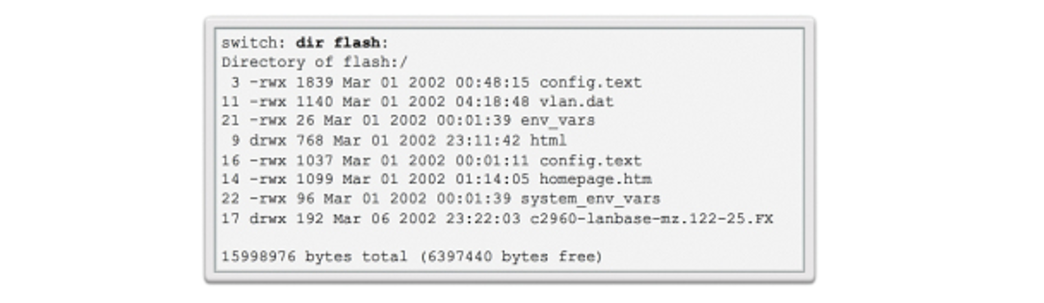
For example, the dir command can view a list of files within a specified directory, as shown in the directory listing in boot loader below.
Switch LED Indicators
Cisco Catalyst switches have several status LED indicator lights. You can use the switch LEDs to monitor switch activity and its performance quickly.
Switches of different models and feature sets will have different LEDs, and their placement on the switch's front panel may also vary.
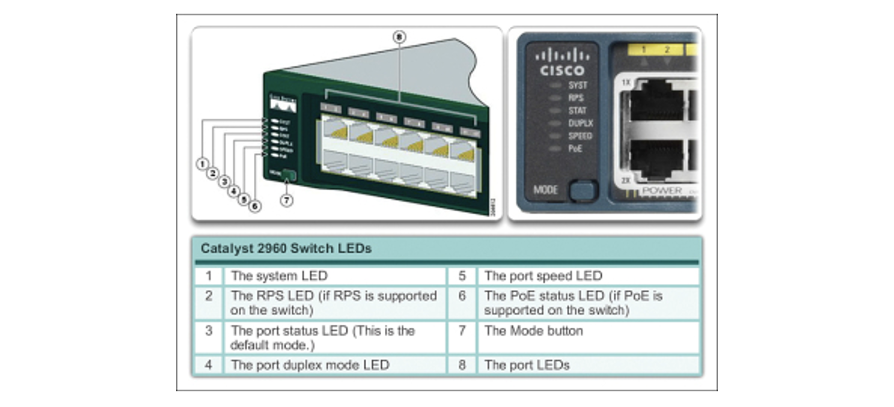
The image below shows the switch LEDs and the Mode button for a Cisco Catalyst 2960 switch. The Mode button is used to toggle through port status, port duplex, port speed and PoE (if supported) status of the port LEDs.
Preparing for basic switch management
To prepare a switch for remote management access, the switch must be configured with an IP address and a subnet mask. Keep in mind that the switch must be configured with a default gateway to manage the switch from a remote network. This is very similar to configuring the IP address information on host devices.
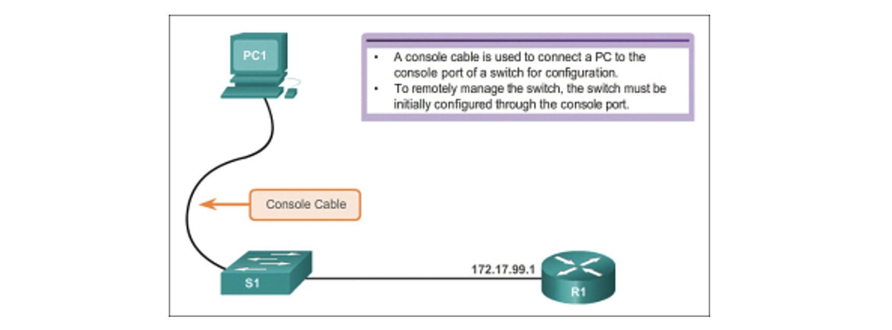
In the figure below, the virtual switch interface (SVI) on S1 should be assigned an IP address. (The SVI is a virtual interface, not a physical port on the switch.)
SVI is a concept related to VLANs. VLANs are numbered logical groups to which physical ports can be assigned. Configurations and settings applied to a VLAN are also applied to all the ports assigned to that VLAN.
By default, the switch is configured to have the switch's management controlled through VLAN 1. All ports are assigned to VLAN 1 by default. For security purposes, it is considered a best practice to use a VLAN other than VLAN 1 to manage VLAN. Furthermore, it is also a best practice to use a VLAN that end devices such as users and printers do not use.
Note: These IP settings are only for remote management access to the switch; assigning an IP address to the switch does not allow the switch to route Layer 3 packets.
Configuring basic switch management access with IPv4
Configure the Management Interface
An IP address and subnet mask are configured on the switch's management SVI from VLAN interface configuration mode. The IP address command is used to configure the IP address. The no shutdown command enables the interface.
Note: The SVI for VLAN 99 will not appear as 'up/up' until VLAN 99 is created, the IP address assigned to the SVI, the no shutdown command entered, and either:
- (1) a device is connected to an access port associated with VLAN 99 (not a best practice) or
- (2) connects to another network device such as a switch.
Configure the Default Gateway
The switch should be configured with a default gateway if the switch will be managed remotely from networks not directly connected.
The default gateway is the first Layer 3 device (such as a router) on the same management VLAN network the switch connects to. The switch will forward IP packets with destination IP addresses outside the local network to the default gateway.
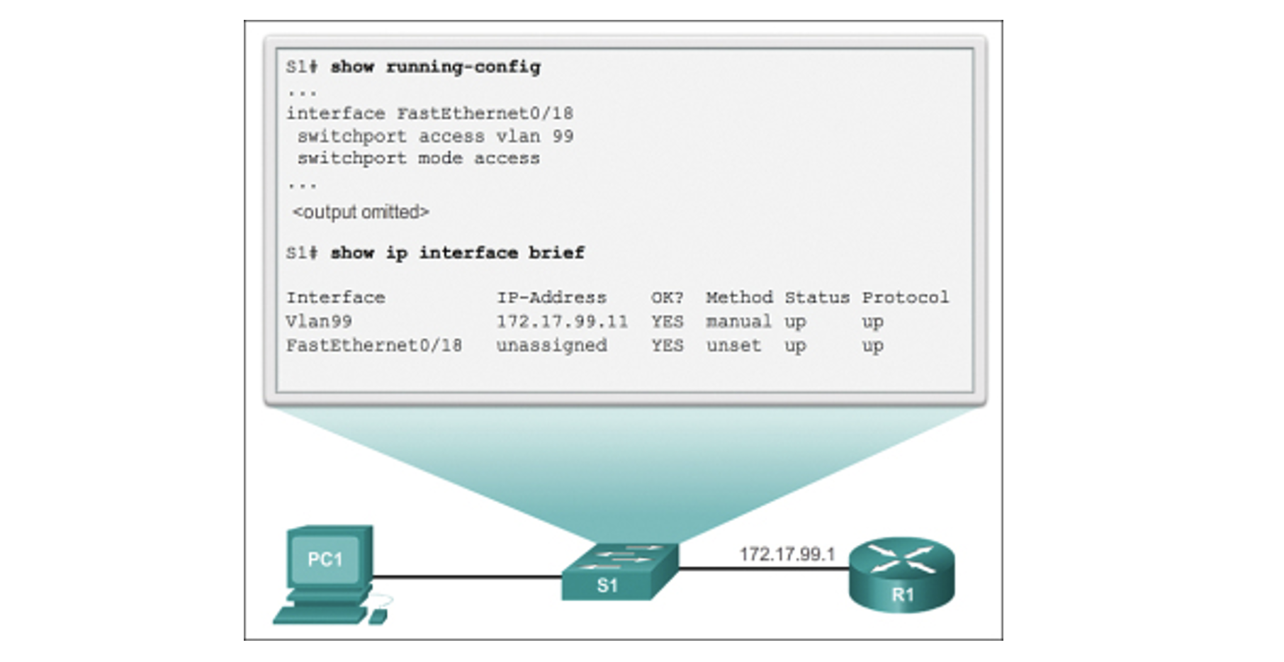
As shown in the figure below, R1 is the default gateway for S1. The interface on R1 connected to the switch has IP address 172.17.99.1. This address is the default gateway address for S1.

To configure the default gateway for the switch, use the IP default-gateway command. Enter the IP address of the default gateway. The default gateway is the IP address of the router interface to which the switch connects. Use the following command to backup the configuration: copy running-config startup-config.
Verify the Configuration
As shown in the figure below, the show IP interface brief command is useful when determining the status of both physical and virtual interfaces. The output shown in the figure confirms that interface VLAN 99 has been configured with an IP address and a subnet mask and that FastEthernet port Fa0/18 has been assigned to the VLAN 99 management interface. Both interfaces are now 'up/up' and operational.
Test an Ethernet switch
For small businesses that need to connect a large number of nearby computers to the internet, setting up a local wired network may be a cheaper solution than installing wireless routers and access points.
The key hardware involved in a wired network is an Ethernet switch, sometimes also called an 'Ethernet hub'.
An Ethernet switch splits the internet connection from a single source and shares it between 4 computers.
- Connect your laptop directly to your network source--a modem or router--using an Ethernet cable. Open a Web browser to see if you can access the internet. If you are successful, your modem or router is working properly.
- Connect one Ethernet cable from your modem or router to the port labelled 'WAN' on your Ethernet switch.
- Connect the other Ethernet cable from your laptop to the 'LAN 1' port on your Ethernet switch.
- Press the 'Reset' button on the back of your modem or router to reboot the device. If you do not reset the device, it may not recognise the Ethernet switch.
- Plug the Ethernet switch's power adapter into a wall outlet once the modem or router has finished rebooting.
- Check for blinking green lights above the 'WAN' and 'LAN 1' ports. A blinking green light represents an active connection. Open a Web browser on your laptop to confirm that the connection is active.
- Disconnect the Ethernet cable from 'LAN 1' and plug it into each of the remaining ports on the Ethernet switch. When testing each port, look for a blinking green light, and then test the connection by opening a Web browser on your laptop.
Testing
In addition to ensuring a device can perform a basic task (such as printing a test page or scanning an image), it is also necessary that all functionality required by the client is tested.
When new peripheral equipment is not tested for critical functions before being used, it can lead to malfunction, causing large disruptions to clients and potentially damaging other parts of a computer system.
If, for example, a client's new external zip drive has not been tested to check it will be capable of making backups of specific files, it could mean that vital information could be destroyed should those backups not be successful.
Ensure that all new installations are thoroughly tested:
- after initial setup
- before use by the client.
Depending on the device, different functions will need to be tested.
Devices that have components known to degrade with time--especially printers--should also be tested periodically. Printers need to be routinely tested, as components such as the ink cartridges and toner can cause deterioration of print quality and may require maintenance and cleaning.
All tests should be completed according to a documented test plan.
Some suggestions of functions that may be tested for printers and scanners are included below.
Printer
Printer functions that may be tested are suggested below.

Scanner
To check scanner functionality, you might ask:
- Is the resolution of a scanned image an acceptable quality?
- Does the scanner work correctly with different software packages (e.g. word processor or desktop publishing package)?
- Can the scanner handle items of unusual size and thickness (e.g. a large book)?
- Does the OCR software scan a document successfully?
- Will the scanner work successfully on other computers?
What is a test plan?
A 'test plan' is used to work out a structured process to ensure that a new device will work under all ordinary circumstances. It logically describes:
- functions that need to be tested
- an example test case scenario
- expected results for each scenario
- what happens once the test has been performed.
Example test case scenarios should simulate realistic work patterns (i.e. the scenario should realistically demonstrate if a function will be satisfactory after implementation).
Because testing is critical to the successful implementation of the new device, it is important that a test plan is comprehensive and considers every way a device will need to function after implementation. It is useful to refer back to the client's requirements to remember functions that the client will regularly expect.
The following sample printer test plan scenarios act as a checklist to ensure that the printer works to acceptable client requirements.
| Function | Scenarios | Expected results | Actual results |
|---|---|---|---|
| Printer can produce acceptable quality prints of word processing, spreadsheets and desktop publishing pages. |
|
|
|
|
Printer handles irregular-sized paper |
|
|
|
|
Photos and colour are acceptable quality |
|
|
|
|
Displays appropriate error message when problem occurs |
|
|
Instructions - Think about how you would answer these questions.
- What is the difference between working with static IP and managing the IP addresses of the switch with DHCP?
- What are the switch boot sequence's five steps?
- What are the factors to consider while testing an ethernet switch?
If you could not answer these questions, it is recommended that you review the learning material in this topic.
Share your answers and comments with your peers on the forum.