One of the defining features of a network is its responsibility to connect people, devices, and information securely. In this topic, we will focus on how devices are connected to allow data sharing and the ability for millions worldwide to communicate and connect online.
A network consists of two or more computers connected by a transmission medium, such as Ethernet cables or Wi-Fi.
But first, to understand how networks work, you need to learn about the underlying technologies and devices used.
In this topic, we will look into:
- Network devices
- Ethernet
- Cables and testing tools
- Wireless networks
A good place to start is by looking at the components that turn a stand-alone computer into one that is part of a network. The following list identifies the hardware devices used to connect computers and other electronics to a network.21
Collectively, these hardware items are called network devices, or sometimes network appliances:
- Hubs and repeaters
- Bridges
- Managed and unmanaged switches
- Routers
Hubs and repeaters

A hub is a device used to implement the ethernet connection inside the equipment to provide connections for network devices. A hub, working as a multiport repeater, will replicate the signal received from one port and send it over to all other ports in the network.22,23

A repeater is a device used to overcome the distance limitations imposed by network cabling. It receives a signal over one cable segment and then regenerates and retransmits it at the original strength over another cable segment.


Bridges
A bridge is a device that divides a local network into two or more segments.

Hosts from one segment can only communicate with those on another via the bridge. A bridge is used to divide an overloaded network into separate collision domains. A collision happens when two computers use media simultaneously, so both computers are denied the transmission and have to back off and wait for a random time before trying again. Collision domains spread the load.
The bridge keeps track of the MAC addresses attached to each segment. It only passes signals from one segment to another if there is a match to the destination MAC address, which reduces traffic loads in any one segment.

Managed and unmanaged switches
An unmanaged switch performs the micro-segmentation function described without requiring configuration. You plug in the network cable, power it on, and it's good to go.
Larger workgroups and corporate networks require additional functionality in their switches. Switches designed for larger LANs are called managed switches.

One of the main reasons for using managed switches is that enterprise networks might have to provide hundreds or thousands of access ports. This is accomplished by linking multiple switches together.
The functionalities provided by a managed port include:
- Remove management
- VLANs
- Port security
However, having many ports on the same network may create performance and security issues, so managed switches are used by dividing the ports into separate Virtual LANs (VLANs) where they can be configured and monitored, which will enhance performance and security. VLANS will be covered in a later topic.

| Unmanaged | Managed |
|---|---|
| Fixed configuration | can be managed and configured accordingly |
| Plug and play | Requires IT personnel to set up and maintain |
| VLAN support- No | VLAN support- Yes |
| No control over traffic | Control over LAN traffic |
| No security settings | Security can be controlled over access |
| A simple network management protocol (SNMP) is not an option | Allows for remote troubleshooting of network |
| Cost-effective | More expensive |
| Basic features | Features including VLANs, port mirroring and redundancy included |
Routers
A router is responsible for moving data across different networks. While a switch forwards frames using hardware (MAC) addresses within a single network segment, a router forwards packets across different networks using IP addresses.

When you want to connect a network to the Internet or when you want to divide a large network into smaller networks, you need to use one or more routers.
Network address translation
Most routers implement Network Address Translation (NAT). They implement Network Address Port Translation (NAPT), also referred to as NAT overloading or Port Address Translation (PAT).
The router/modem is assigned with a single public IP address by the ISP. Most ISP will allocate a dynamic IP address to the home user instead of a static IP address. Hosts connected to the router/modem's switch or access point are configured with local (private) addresses, typically 192.168.0.0/24 or 192.168.1.0/24.
![]()
Port forwarding and Port triggering
When NAT overloading is deployed, hosts on the Internet can only "see" the router and its public IP address. If you want to run a server application from your network and make it accessible to the Internet, you need to set up port forwarding or Destination NAT (DNAT).
Port forwarding means that the router takes requests from the Internet for a particular protocol and sends them to a designated host on the LAN. The request could also be sent to a different port, so this feature is often also called port mapping. For example, the Internet host could request HTTP on port 80, but the LAN server might run its HTTP server on port 8080 instead.
Port triggering is used to set up applications that require more than one port. When the firewall detects activity on outbound port A destined for a given external IP address, it opens inbound access for the external IP address on port B for a set period.
Whitelists/blacklists
As content flows through the network, security filters can be applied. Whitelists and blacklists identify safe or potentially malicious transmissions.
Blacklists are comprised of URLs known to harbour a particular type of potentially harmful content. There will be separate blacklists for different types of content that users might want to block. There are also blacklists of sites known to host malware. The firewall will block any IP address or domain name appearing on a blacklist for which a filter has been configured.
Conversely, whitelisting a site will authorise all transmissions from that site. One way to lock down Internet usage very tightly is to configure a filter where only whitelisted sites are accessible.
Demilitarised zone (DMZ)
When making a server accessible to the internet, careful thought needs to be given to the security of the local network. A simple firewall with port forwarding will allow servers access from outside to the local network, making the network vulnerable to Internet traffic.
If a server is compromised because it is on the local network, other LAN hosts can also be attacked, and the attacker could examine traffic passing over the LAN. A Demilitarized Zone (DMZ) is important as it is a means of establishing a more secure configuration.
The idea of a DMZ is that hosts placed within it are untrusted by the local network zone. Some traffic may pass between the DMZ and the local network, usually with a second firewall, but no traffic is allowed to pass from the Internet to the local network through the DMZ.

For more information about DMZ, click on the following video, which will explain how and why a DMZ may be used
What is Ethernet
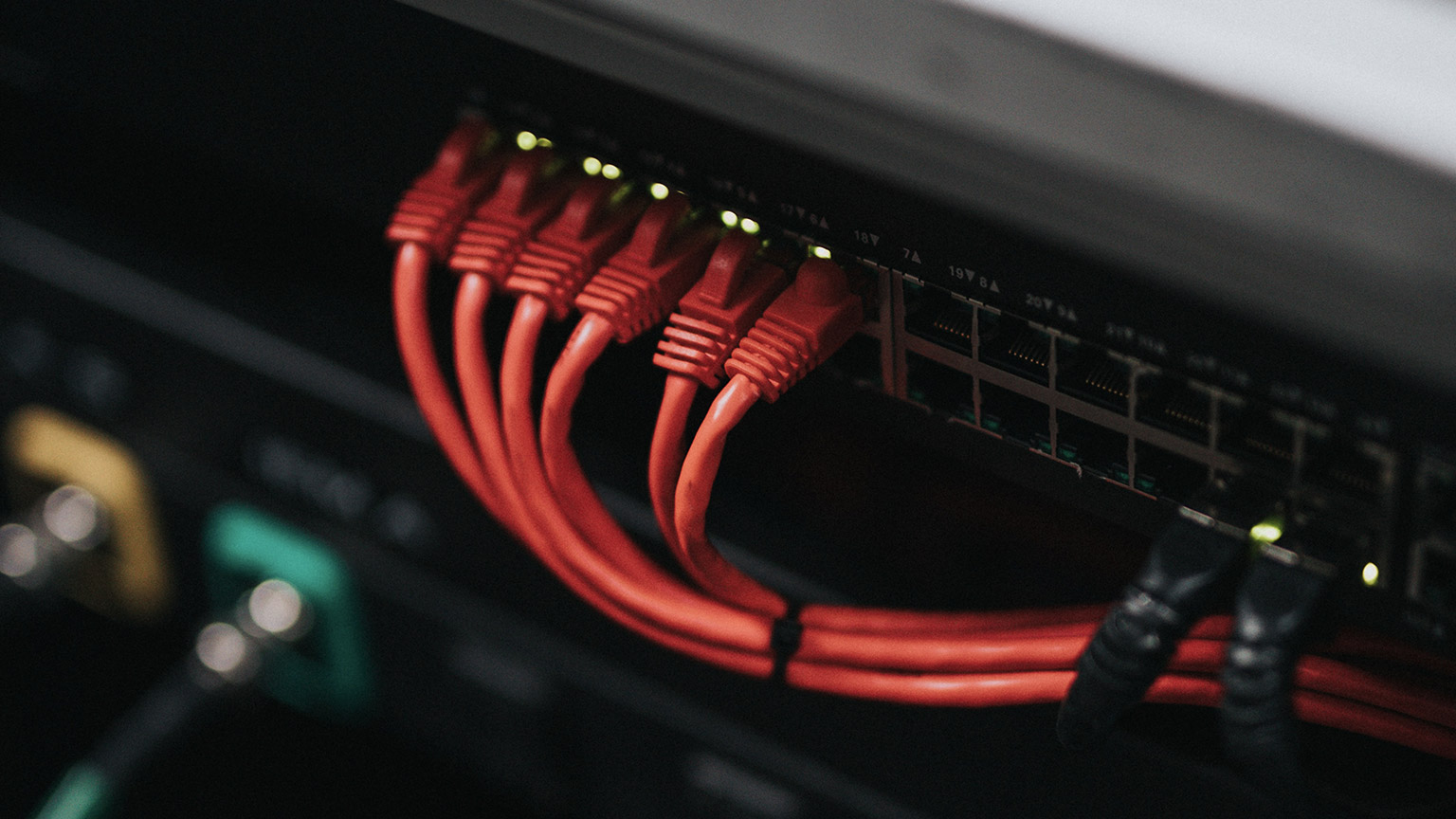
Before Wi-Fi was used, there was Ethernet for fast and reliable network connection. Ethernet cables connect devices such as PCs, routers, and switches within a local area network.
Ethernet is still used today and remains the traditional way of connecting devices to transmit data. It has physically encased wiring over which the data will travel through. It has a blue or yellow casing with a square plastic connector known as RJ45. They come in various lengths, from 90cm to 100 meters.
See the image below for a visual understanding:

Ethernet types and standards
The Institute of Electrical and Electronics Engineers (IEEE).
The series technically know ethernet standards produced by the IEEE 802.3 working group. Although the product name is not normally used in the documentation and has come to be universally referred to as Ethernet.
Ethernet is a very flexible technology and can support a wide range of different types and sizes of LAN. While a LAN is self-contained, that does not mean that it has to be small. LANs can range from networks with three or four nodes to networks with thousands of nodes at the same general location.
Types of ethernet
- 10 Mbps (10BASE-) is the original standard, specifying cabling and connectors for copper wire and fibre optic products.
- Fast Ethernet (100BASE-)—copper wire and fibre optic implementations of 100 Mbps LANs.
- Gigabit Ethernet (1000BASE-)—1000 Mbps LANs. This has replaced Fast Ethernet as the "standard" for a typical LAN.
- 10G Ethernet (10GBASE-)—10 Gbps links for LANs and WANs, mostly fibre optic media. 10G Ethernet is widely used in data centres.
The IEEE 802.11 series of standards (Wi-Fi) are used to implement Wireless Local Area Networks (WLAN), so the technologies complement one another and are often used together in the same network.
Network Interface Card

The physical connection to the network is made using a port in the computer's Network Interface Card (NIC). For the NIC to be able to transmit and receive the signals and process them as digital data, they must be divided into regular units with a consistent format. it acts like a trans-receiver, where it can transmit and receive at the same time while communicating with other devices.
Ethernet provides a data link protocol to perform these framing and addressing functions. The signalling mechanism uses various encoding methods to represent the 1s and 0s of computer data as electrical or light pulses. The transceiver in the NIC is responsible for transmitting and receiving these pulses in the agreed frame format.
Frames

Each frame is identified by a preamble sequence, which warns the NIC to expect a new frame. A frame is formatted with control information in the form of header fields, each of a fixed size and presented in a fixed order. The most important fields are the destination and source addresses of the adapter to which the frame is directed and the adapter from which it was sent.
Following these fields comes the payload. This is the data that is being transported over the network. It will normally consist of a network packet, such as an Internet Protocol (IP) packet, with headers and payload. Putting layers of packets within one another like this is called encapsulation. The frame finishes with a checksum. The receiving computer can calculate its checksum and compare it to this value. If they do not match, the receiving host rejects the frame as damaged.
For more information on how frames-work, check out the following video
Media access control (MAC)
Each device on your network has a unique 12 digit hexadecimal ID number called a MAC address; it identifies which device is under a local network. When data arrives at your home, the router device will need to identify which device to send that data to; it does this by keeping track of the MAC addresses of all the devices connected to it. It will then assign a private IP address to every device.
For more information on MAC address, watch the following video.
Cables are the medium in which information moves from one network device to another. There are several types of cables that are commonly used with LANs. In some cases, a network will utilise only one cable type; other networks will use various cable types. Understanding the characteristics of different cable types and how they relate to other aspects of a network is necessary to develop a successful network.
Some examples of cables used to connect a successful network include:
- Unshielded twisted pair cable
- Shielded twisted pair cable
- Plenum cable

Unshielded twisted pair (UTP) cable
Unshielded Twisted Pair (UTP) is the type of cabling most widely used for computer networking. With the type of UTP used for Ethernet, the cable contains four copper conductor "pairs." Each conductor has an insulating sheath. Each pair of conductors is twisted, which reduces interference between the wires (crosstalk) and interference from other electromagnetic sources, referred to as Electromagnetic Interference (EMI).
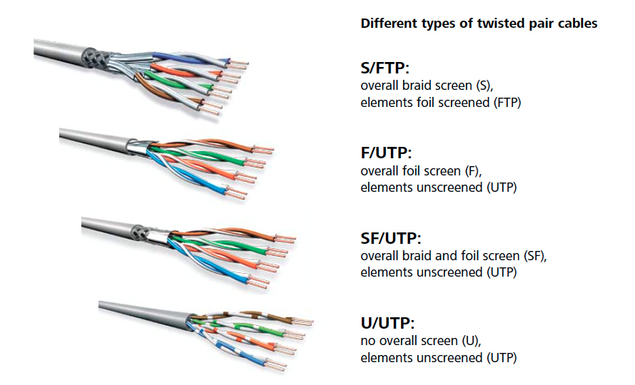
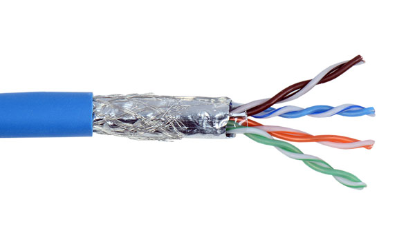
Shielded twisted pair
(STP) When twisted pair cabling was first used, it was usually shielded to make it less susceptible to interference and crosstalk. A braided shield surrounded each pair. This cable construction is referred to as Shielded Twisted Pair (STP). STP is bulky and difficult to install, so where a degree of protection from interference is required, modern twisted-pair cabling installations use screened cables, meaning a shield positioned around all pairs. There are many different ways of designating various types of shielding. Most Cat 5e/ 6/6A cable is available in shielded variants, notably F/UTP and U/FTP:
- F/UTP—with a foil screen around all pairs, often designated ScTP.
- U/FTP—with foil shielding for each pair
Plenum cable
A plenum space is a void in a building designed to carry Heating, Ventilation, and Air Conditioning (HVAC) systems.
Plenum space is typically a false ceiling, though it could also be constructed as a raised floor. This space has also been used for communications wiring in some building designs, making installation simpler. Plenum space is an effective conduit for fire, as there is plenty of airflow and no fire breaks, such as walls and doors. If the plenum space is used for heating, there may also be higher temperatures. When burned, plenum cable must not emit large amounts of smoke, be self-extinguishing, and meet other strict fire safety standards. General-purpose (non-plenum) cabling uses PVC (polyvinyl chloride) jackets and insulation.
CAT Standards
The number of twists per feet will determine the speed and transmission limitations of the cable. Some of the features are included in the following table.
| CAT | FREQUENCY | CAPACITY | MAX.DISTANCE | NETWORK APPLICATION |
|---|---|---|---|---|
| 5 | 100MHz | 100 Mbps | 100 m | 100BASE-TX |
| 5e | 100MHz | 1 Gbps | 100 m | 100BASE-TX |
| 6 | 250MHz | 1 Gbps | 100 m | 1000BASE-TX |
| 6 | 250MHz | 10 Gbps | 55 m | 10GBase-TX |
| 6a | 500MHz | 10 Gbps | 100 m | 10GBase-TX |

Patch panels and structured cabling
A Gigabit Ethernet link using twisted pair cabling can be 100m long. This means there must be no more than 100 m of cabling between the switch and the computer. There is also a distinction between solid and stranded cabling. Solid cabling uses a single thick wire for each conductor. Solid cable is used for "permanent" links, such as cable running through walls.
A patch cord is made using stranded cable, which comprises many very thin wires twisted to make a single conductor. This makes the cable much more flexible but less efficient. A patch cord is not supposed to be longer than 5 meters.
To undergo cabling work, you will need to use various tools. Of course, the range of tools you require will depend on the cabling work, but the following can be considered the tools generally used.
- Wire stripper/cutter
- Punch down tool
- Crimpers
- Cable testing tools
- Tone generator and probe
- Loopback plugs
- Fibre optic cabling and connectors
- Coaxial cabling and connectors

Wire stripper/cutter
Wire strippers are designed for cutting copper wire and stripping insulation and cable jackets. Alternatively, some dedicated tools or tools have replaceable blades for different data cable types. Cable cutting blades should be rounded to preserve the wire geometry. Stripping tools should have the correct diameter to score a cable jacket without damaging the insulation around each wire.

Punch down tool
These tools fix conductors into an Internet database connector. It is important not to untwist the pairs too much, however. The punch-down tool then presses the wire into the terminal, cutting through the insulation to make an electrical contact.

Crimpers
These tools fix a jack to a cable. As with an Internet database connector, the wires are laid in the appropriate terminals in the jack, and the crimper tool then closes and seals the jack. The tools are specific to a particular type of connector and cable.
Cable testing tools
After making all the connections, the best time to verify wiring installation and termination. This means you should still have access to the cable runs. Identifying and correcting errors at this point will be much simpler than when you are trying to set up end-user devices. When troubleshooting a cabled network link, you may need to consider:
- the patch cord between the PC and the wall port
- the wall port and the cabling in the wall
- the port on the patch panel and the patch cord to the switch port.
A multimeter can be used as a basic cable testing tool. The primary purpose of a multimeter is for testing electrical circuits. Still, you can use one to test for the continuity of any sort of copper wire, the existence of a short, and the integrity of a terminator.24
To perform useful tests, you need to know the expected readings from a particular test. For example, suppose the resistance measured across UTP Ethernet cable is found to be 100 ohms (units that measure electrical resistance). In that case, the cable is OK, but if the resistance between the two ends of a cable is infinity, they may be damaged.

Tone generator and probe
A tone generator and probe tool are used to trace a cable from one end to the other. This may be necessary when the cables are bundled and have not been labelled properly.
- The tone generator is used to apply a signal on the cable.
- The probe is used to detect the signal and follow the cable over ceilings and through ducts or identify it from within the rest of the bundle.
To locate a cable in a group of cables, connect the tone generator to the copper ends of the wires, then move the tone locator over the group of cables. A soft beeping tone indicates you are close to the correct wire set; you have found the cable when the beeping is loudest.
Loopback plugs
A loopback plug is used to test a port to diagnose whether a device is working effectively. It involves connecting pin 1 to pin 3 and pin 2 to pin 6 by rewiring the jack or twisting the relevant pairs together on a cable stub.25
Fibre optic cabling and connectors
Copper wire carries electrical signals, which are subjected to interference. Fibre optic cabling can support much higher bandwidth than copper wire, measured in multiple gigabits or terabits per second, and longer cable runs, measured in miles rather than feet.
An optical fibre consists of an ultra-fine core of glass to carry the light signals surrounded by glass or plastic cladding, which guides the light pulses along with the core, and a protective coating called the buffer. The fibre optic cable is contained in a protective jacket and terminated by a connector.

Fibre optic cables fall into two broad categories: single-mode and multi-mode.
- Single-Mode Fibre (SMF) has a small core and is designed to carry a long wavelength, near-infrared light signal generated by a laser. They support data rates up to 10 Gbps or better and cable runs of many kilometres.
- Multi-mode (MMF) has a larger core and is designed to carry a shorter wavelength of light transmitted in multiple waves of varying lengths.
Several connectors have been designed for use with fibre optic cabling. Some types are more popular for multi-mode and some for single mode.
- Straight Tip (ST)—A bayonet-style connector that uses a push-and-twist locking mechanism for multi-mode networks.
- Subscriber Connector (SC)—A connector with a push/pull design allows simpler insertion and removal.
- Lucent or Local Connector (LC)—A small form factor connector with a tabbed push/pull design. This is similar to the Subscriber connector, but the smaller size allows for higher port density.
Patch cords for fibre optic can come with the same connector on each end or a mix of connectors. Fibre optic connectors are quite easy to damage and should not be repeatedly plugged in and unplugged.

Coaxial cabling and connectors
Coaxial or coax cable is a different copper cabling that also carries electrical signals. Where twisted pair uses balancing to cancel out interference, coax uses two conductors that share the same axis. The core signal conductor is enclosed by plastic insulation (dielectric) then a second wire mesh conductor serves both as shielding from EMI and as a ground.26
Power over Ethernet (POE) is a technology that allows network cables to carry electrical power from a switch port over data cabling to a connected, powered device, such as a networked security camera.
PoE is defined in two IEEE standards (now both rolled into 802.3-2012):
- 802.3af—powered devices can draw up to about 13 W over the link. Power is supplied as 350mA@48V and limited to 15.4 W, but the voltage drop over the maximum 100 feet of cable results in usable power of around 13 W.
- 802.3at (PoE+)—powered devices can draw up to 25 W.
When a device is connected to a port on a PoE switch, the switch goes through a detection phase to determine whether the device is PoE-enabled. If not, it does not supply power over the port and therefore does not damage non-PoE devices.
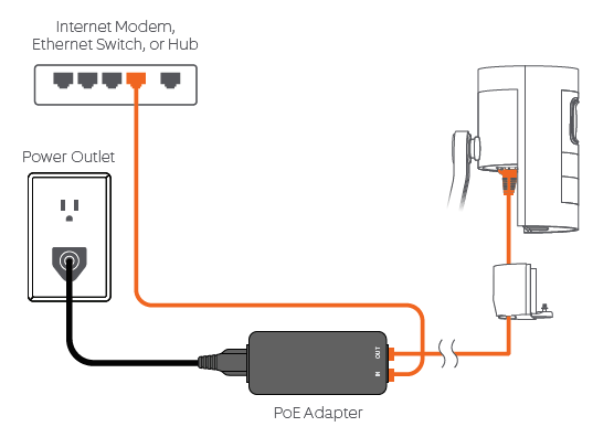
If so, it determines the device's power consumption and sets the supply voltage level appropriately. Powering these devices through a switch is more efficient than using a wall-socket AC adapter for each appliance. It also allows network management software to control the devices and apply power schemes, such as making unused devices go into sleep states and power capping.
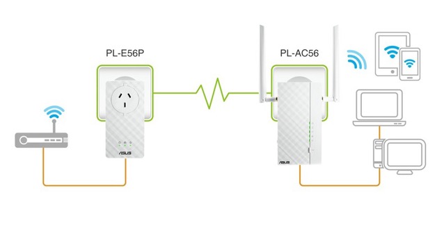
Many SOHO networks will be based on a single Internet router, server computer, and workstations, possibly located within the same room. Your home may also require network to connect your smartphone, appliances, and consoles. The main challenge with this is usually joining up the location selected for most of the equipment with the location of the Internet access line.
An obvious solution for connecting SOHO devices is wireless. For many SOHO networks, the bandwidth available for WLANs will be adequate. However, there may be interference issues, and some home appliances might not support Wi-Fi.
As an alternative to installing new data cabling, Ethernet over Powerline products can use building power circuits. A network connection is established via a Powerline adapter plugged directly into an electrical outlet. The adapters automatically detect and communicate over the electrical wiring with no configuration needed.
Wireless networks can be defined as a computer network that uses wireless data to allow devices to stay connected. Wireless networks replace wired ports and can connect without cables or wires.
Wireless can provide connectivity for desktops or even servers in places where it is difficult or expensive to run network cabling.
Wireless networking overview
"Wireless" encompasses a range of connectivity products and technologies, from personal area networking to Internet connectivity. Most wireless technologies use radio waves as transmission media. Radio systems use transmission and reception antennas tuned to a specific frequency to transfer signals.
Frequencies, range, and channels
The radiofrequency (RF) range extends from 3 KHz to 300 GHz. Frequencies are subdivided into bands such as very low and ultra-high.
Wireless LAN standards
When talking about "wireless networking" for desktops, laptops, smartphones, and tablets, the term is generally understood to mean the IEEE's 802.11 standards for Wireless LANs (WLANs), also called Wi-Fi. There are five main versions of the standard, as summarized here:
| Standard | Maximum Transfer Rate | Band |
|---|---|---|
| 802.11a (1999) | 54 Mbps | 5 GHz |
| 802.11b(1999) | 11 Mbps | 2.4 GHz |
| 802.11g (2003) | 4 Mbps | 2.4 GHz |
| 802.11n (2009) | 288.8 Mbps (single channel) 600 Mbps/stream (bonded channels) |
2.4 GHz / 5 GHz |
| 802.11ac (2013) | 1.7 Gbps (at time of writing) | 5 GHz |
The actual data rate will drop with distance and in the presence of interference, with the preference being for a slower, stable connection over a faster, error-prone one
Frequencies
Every wireless device operates on a specific radio frequency within broadband. Understanding the difference between the two most common frequency bands in the IEEE 802.11 standards: 2.4 GHz and 5.0 GHz.
- 2.4 GHz is the longer wavelength, which gives it a longer range and makes it better at propagating through solid surfaces. However, the 2.4 GHz band does not support a high number of individual channels. It is often congested with other Wi-Fi networks and other types of wireless technology, such as Bluetooth.
- 5 GHz is less effective at penetrating solid surfaces and does not support the maximum ranges achieved with 2.4 GHz standards. Nonetheless, the band supports more individual channels and suffers less from congestion and interference, meaning it supports higher data transfer rates.

Range
Products working in the 2.4 GHz band can have a maximum indoor range of anywhere from 30 to 45 m).
Products using 5 GHz are usually quoted as having a maximum range of about one third less (up to about 30 m).
Channels
The 2. band is subdivided into up to 14 channels, spaced at 5 MHz intervals from 2412 MHz to 2484 MHz. Wi-Fi requires a bandwidth of approximately 20 MHz. Consequently, a site designer needs to choose the channels that do not overlap. On a WLAN where only the first 11 channels are available, channels 1, 6, and 11 can be selected as non-overlapping.
The limited number of non-overlapping channels means that co-channel interference is possible. Special codes embedded in the signal give each transmitting node a distinguishing pattern so that nearby networks can share the same channel at once. At some point, however, the channel becomes saturated with too many WLANs.
The 5 GHz band is subdivided into 23 non-overlapping channels, each ~20 MHz-wide. The greater number of non-overlapping channels means that co-channel interference is less of a problem for the 5 GHz band. This means that more WLANs can occupy the same area or that you can provision more access points closer together to support a greater density of client devices.

Access points and modes
Most Wi-Fi networks are configured in what is technically referred to as infrastructure mode. Infrastructure mode means that each client device (or station) is configured to connect to the network via an Access Point (AP). In 802.11 documentation, this is referred to as a Basic Service Set (BSS). The MAC address of the AP is used as the Basic Service Set Identifier (BSSID). The access point works as a bridge, forwarding communications between the wireless stations and the wired network. The access point will be joined to the network like a host computer via a wall port and cabling to an Ethernet switch.
Ad-hoc and Wi-Fi direct
AD-HOC AND WI-FI DIRECT Stations can also be configured to connect directly. With older network standards, this is referred to as ad-hoc mode. Such peer-to-peer connections are now more likely to be implemented as Wi-Fi Direct, which has the advantage of automatically configuring a secure link between the stations
WMN topology
The 802.11s standard defines a Wireless Mesh Network (WMN). Unlike an ad hoc network, nodes in a WMN (called Mesh Stations) are capable of discovering one another and peering, forming a Mesh Basic Service Set (MBSS). The mesh stations can perform path discovery and forwarding between peers using a routing protocol, such as the Hybrid Wireless Mesh Protocol (HWMP).

Personal Area Networks
The concept of a Personal Area Network (PAN) has gained some currency with the profusion of wireless and cellular connection technologies in the last few years. A PAN refers to wireless connectivity connecting devices within a few meters— printers, smartphones, headsets, speakers, video displays, etc.
Wireless network card
Each station in a Wi-Fi network needs to be installed with a Wi-Fi adapter supporting the 802.11 standard(s) used on the network. A Wi-Fi adapter can be installed if the function is not available on the motherboard. Both internally installed adapter cards and USB-connected adapters are available.

Wi-fi security protocols
Wireless LANs require careful configuration to make the connection and transmissions over the connection secure. The main problem with wireless is that because it is "unguided," there is no way to contain the signal. Anyone with a suitably equipped laptop or RF (Radio Frequency) scanner can intercept the signals. If the proper security has not been put in place, this could allow the interception of data or the unauthorized use of the network.
An encryption system consists of a cipher, the process used to scramble the message, and a key. The key is a unique value that allows the recipient to decrypt a message that has been encrypted using the same cipher and key. The key must be known only to valid recipients, or the encryption system will offer no protection. We will learn more about the importance of using keys in encryption later in this module.
The Wired Equivalent Privacy (WEP)
An encryption system is based on the RC4 cipher. RC stands for Ron's Cipher, after its inventor, Ron Rivest. Under WEP version 1, you can select from different key sizes (64-bit or 128-bit). A larger key makes it more difficult to attack the security system.
Wi-fi protected access
(WPA) Wi-Fi Protected Access (WPA) fixes most of the security problems. WPA still uses the RC4 cipher but adds a mechanism called Temporal Key Integrity Protocol (TKIP) to fix the issues with key generation.
Wi-fi authentication
It is possible to configure a WLAN as open, meaning anyone can connect to it. However, to secure the WLAN, you need to confirm that only valid users connect to it by authenticating them. WLAN authentication comes in two types.
- Personal
- Enterprise.
Personal
The personal authentication mode is based on a Pre-shared Key (PSK). This is the key that is used to encrypt communications. A PSK is generated from a passphrase, like a long password. In WPA-PSK, the router administrator defines a passphrase of between 8 and 63 ASCII characters. This is converted into a 256-bit cryptographic hash, expressed as a 64-digit hex value where each hex digit represents 4 bits.
Enterprise
WPA and WPA2 can implement enterprise mode authentication, where the access point passes authentication information to a Remote Authentication Dial-in User Service (RADIUS) server for validation. This type of authentication is suitable for server-/domain-based networks.
Scenario:
You have been hired to perform a wiring job. The organisation has a relationship with a supplier to purchase the media and components and you need to specify the correct cable(s) to use. The plan is to install a network using copper cabling that will support Gigabit Ethernet. Some of the cabling will be used in a building void that houses an HVAC system. The organisation's supplier has a deal on Cat5e cable spools and they have asked if that is the best choice for the entire job.
How would you answer them and what explanation can you give for your answer? Please discuss your ideas on the forum with your peers.