About this topic
We’re halfway through the course! In Rigging, we will dive into the rigging process, a workflow that gives structure and animation capabilities to your 3D models. We will explore critical aspects of rigging including joints and handles, constraints, parenting and skin binding, and weight painting. To conclude, you’ll be able to apply rigging techniques to a biped model, helping you create a structure that will enable realistic movements.
Having learned about creating and texturing 3D models it is time to get them ready for movement through rigging. Rigging refers to the process of creating a digital skeleton or structure within a 3D model that enables it to be animated. It involves adding a system of joints, bones, controls, and constraints to a character or object to define its movement, deformation, and behaviour.
In rigging, the digital skeleton acts as a framework for the 3D model, providing a hierarchical structure of interconnected parts. The joints represent the articulation points or pivot points that allow the model to move and deform realistically. The bones connect these joints, defining the relationships and range of motion between them.

Rigging serves as the bridge between the static 3D model and the animator's control. It provides a way to manipulate and animate the model by posing the joints and controlling the skeleton's movements. By adjusting the positions and rotations of the joints, animators can achieve lifelike movements such as walking, running, or facial expressions.
Rigging also involves creating control systems that allow animators to manipulate the rig more easily. These control systems can be custom-made controllers, such as handles or on-screen widgets, which provide intuitive interfaces for animators to pose and animate the rig. Additionally, constraints can be applied to limit the movement or behaviour of certain parts of the rig, ensuring that it moves in a natural and physically plausible manner.
The rigging process requires technical knowledge of 3D software, such as Autodesk Maya, and an understanding of anatomy, movement principles, and animation principles. It requires careful consideration of the model's topology, joint placement, skinning (binding the model to the rig), and creating an efficient and user-friendly control system.
Rigging is essential for creating lifelike and expressive animations in Maya. Here's a general guide on how to use rigging in Maya:
- Create a Skeleton: Start by creating a skeleton for your character or object. In Maya, you can use the Joint tool to place individual joints or bones in the desired locations. Ensure that the joint hierarchy follows the natural structure of the model, with parent-child relationships representing the connections between bones.
- Adjust Joint Orientation: After creating the skeleton, you may need to adjust the joint orientations to ensure they align properly with the model's structure. Maya provides tools for rotating and aligning joints to achieve the desired orientations.
- Skin the Model: Once the skeleton is in place, it needs to be connected to the model's geometry. This process is called skinning or binding. In Maya, you can use the Skin > Bind Skin option to associate the joints with the model. This creates a smooth binding between the joints and the model's vertices, allowing the model to deform realistically during animation.
- Paint Weights: After binding the skin, you'll need to adjust the influence or weighting of each joint on the model's vertices. Maya provides the Paint Skin Weights tool, which allows you to fine-tune the influence of individual joints on specific areas of the model. This ensures that the deformation appears natural and controlled during animation.
- Add Control Systems: To facilitate the animation process, you can add control systems or rigs to your rigging setup. Control systems are objects or controls that allow animators to manipulate the rig easily. They can be simple shapes, such as circles or cubes, placed at key joints or areas of the rig. Maya offers various tools to create and customise control systems, such as the Control Rig and Custom Rigging tools.
- Test and Refine: After setting up the rig, it's important to test it by posing and animating the character or object. This helps identify any issues with the rig's functionality or deformations. If necessary, refine the rig by adjusting joint orientations, painting weights, or modifying control systems to ensure optimal control and natural movement.
- Create Animation: Once the rig is finalised and tested, you can begin animating the character or object by manipulating the control systems. Maya provides to bring your various animation tools to bring your rig to life, including keyframe animation and procedural animation options. You can create key poses, define animation cycles, and apply other animation techniques to achieve the desired movement and behaviour
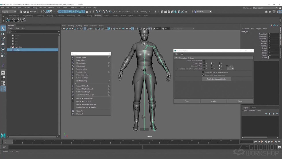
Tutorial 4a: Create joints, controllers and constraints
By the end of this tutorial, you’ll become familiar with the basics of rigging using Maya, including exploring joints, controllers, and constraints to create a basic rigging chain. To work through the tutorial, follow these steps:
- Watch the tutorial’s video below (20min 19sec).
- Interact with the tutorial and Maya.
- Have fun, and ask us if you need any help!
In the context of 3D rigging and animation, joints refer to the key components of a digital skeleton that allow for articulation and movement. Joints serve as the pivot points or connections between different parts of a character or object, enabling them to bend, rotate, and deform realistically.
During the rigging process, joints are placed strategically throughout the character or object to mimic the underlying skeletal structure. They serve as the control points for animation, allowing animators to manipulate the rig and create lifelike movements. By rotating and translating the joints, animators can achieve various poses and motions for characters or objects.
Joints are typically represented as hierarchical structures in a digital rig, forming a chain-like arrangement. Each joint has a position in 3D space and a specific orientation. The orientation of a joint determines the axis along which it can rotate, allowing for movement in specific directions.
Understanding the placement, hierarchy, and behaviour of joints is crucial for creating a well-functioning rig that provides natural movement and deformation. Here are some important aspects and characteristics of joints in rigging:
- Hierarchy: Joints are organised in a hierarchical structure, forming a parent-child relationship. This hierarchy defines the flow of transformations and influences how the rig behaves. Parent joints affect the movement and rotation of their child’s joints.
- Joint Types: Different joint types are used depending on the specific requirements of the rig. Common joint types include root joints, which serve as the starting point of the skeleton, and end joints, which define the extremities or endpoints of a chain. Other joint types include hinge joints, ball-and-socket joints, and more, each offering specific rotation behaviours.
- Position and Orientation: Each joint has a position in 3D space, usually specified by its X, Y, and Z coordinates. Additionally, joints have an orientation that determines their initial rotation or alignment. The orientation is defined by an axis system, such as XYZ or XYZ Euler angles, which determines the rotational freedom of the joint.
- Range of Motion: Joints have a specific range of motion or allowable rotations along their defined axes. This range is often limited to match the natural movement capabilities of real-world joints, ensuring that the rig behaves realistically.
- Influence on Geometry: Joints are used in the skinning process to deform the 3D model or geometry. The movement of the joints affects how the model bends, stretches, and deforms during animation.
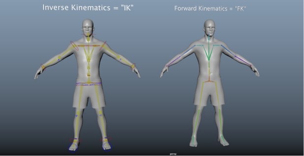
In the context of 3D rigging and animation, IK (Inverse Kinematics) handles are tools or components used to control the movement and positioning of joints in a rig. IK handles allow animators to manipulate the end effector of a chain of joints while automatically calculating the rotations and positions of the intermediate joints.
IK handles are particularly useful for animating character limbs, where achieving natural and believable movements is crucial. They provide a more intuitive and efficient way to control joint chains, offering greater flexibility and control over posing and animation.
Here are some components features of the IK functionality:
Inverse Kinematics
In animation, Inverse Kinematics refers to a mathematical technique used to determine the positions and rotations of a series of linked joints based on the desired movement of the end effector. In contrast to Forward Kinematics, where each joint's rotation is independently set, IK allows animators to control the end position of the chain and automatically calculates the appropriate rotations of the intermediate joints to achieve that position.
Controlling Chain Movement
An IK handle is placed at the end of a joint chain, typically representing a limb such as an arm or leg. By manipulating the IK handle, animators can easily control the movement and positioning of the entire chain, affecting all the connected joints. This simplifies the animation process and allows for a more natural and intuitive posing of characters or objects.
Chain Solvers
Maya and other 3D animation software offer various types of IK solvers that determine how the joints in the chain behave when the IK handle is manipulated. Common types include Single Chain Solver, which provides basic IK functionality for a single chain, and Rotate Plane Solver, which adds additional rotation options to achieve more complex movements. Advanced IK solvers like Full Body IK are available for character rigs with multiple limb chains.
Constraints and Limits
IK handles can be constrained to limit their movement or rotations within specific ranges. Constraints such as pole vectors can be used to control the direction and orientation of the chain, ensuring that it moves in a desired manner. Limits can be set on joint rotations to prevent unrealistic or undesirable bending or twisting.
Animation Workflow
IK handles greatly enhance the animation workflow by simplifying the posing and keyframing process. Instead of individually manipulating each joint in a chain, animators can focus on adjusting the position and orientation of the IK handle, allowing the rig to automatically calculate the appropriate rotations of the intermediate joints.
FK (Forward Kinematics) handles are also tools or components used to control the movement and positioning of joints in a rig. FK involves sequentially manipulating individual parts, like joints or bones, from the base to the tip.
You can control the object's motion by rotating each joint in a hierarchical chain. For instance, when animating an arm with multiple segments and joints, you would rotate the shoulder joint, followed by the elbow joint, and finally, the wrist joint to achieve the desired pose or movement.
The primary advantage of FK lies in its simplicity and intuitive control. It allows for direct manipulation of each joint, making it easy to pose and animate the object or character. However, FK can become more complex when creating intricate movements or interactions between different rig parts.
Watch this video to find out how to set up an FK rig for any model in six steps:
When rigging a character or object in 3D software like Maya, adding rig controls is an essential step to provide animators with intuitive and efficient control over the rig's movement and deformation. Rig controls serve as the user interface for manipulating the rig and can take various forms, such as custom control objects or on-screen manipulators.
You interacted with a video introducing you to rigging in Maya when you worked through ‘Tutorial 4a: Create joints, controllers and constraints’ earlier in this topic. Watch the video again from 6:20 to 16:00 mins to learn the steps to add rig controls:
Control objects give animators clear and intuitive control over the rig's movement and deformations. Properly placed and designed controls can significantly enhance the animation workflow and make it easier to achieve desired poses and movements during the animation process.
Constraints in 3D animation and rigging are tools that define relationships and behaviours between different objects or components within a scene. They enable animators to create complex interactions and control the object's movement, positioning, and deformation.
Constraints allow you to establish rules and connections without directly manipulating every element individually - streamlining the animation process by automating specific interactions and allowing animators to focus on higher-level control and creative decisions.
Here are some commonly used constraints in 3D animation:
- Parent Constraint: This constraint connects two or more objects, making one object the parent of another. The child object inherits the position, rotation, and scale of the parent. Animating the parent will affect the child's transformation accordingly.
- Point Constraint: A point constraint locks an object's position to another object's position. The constrained object moves with the target object but maintains its own orientation and scale.
- Aim Constraint: An aim constraint aligns an object's orientation (usually a camera or directional light) with a target object or a specific point in space. The constrained object continuously points toward the target while maintaining its own position and scale.
- Orient Constraint: This constraint controls an object's orientation to match that of another object or a specific axis. It allows you to control the object's rotation based on the target object's rotation.
- Scale Constraint: A scale constraint maintains a proportional scaling relationship between objects. When the target object scales, the constrained object scales proportionally to maintain the relative size.
- Pole Vector Constraint: This constraint is commonly used in inverse kinematics (IK) setups. It controls the direction or orientation of a joint chain. By assigning a pole vector constraint, you can specify the desired direction or angle of a joint, such as an elbow or knee, in relation to the rest of the limb.
- Surface Constraint: This constraint attaches an object to a surface, allowing it to move and deform along with the surface's geometry. It is useful for creating effects like sticky or conforming surfaces.
Tutorial 4b: Explore all of Maya’s constraints
By the end of this tutorial, you’ll recognise ways to link objects, making Maya’s constraints much simpler to understand by showing you what each does in order. To work through the tutorial, follow these steps:
- Watch the tutorial’s video below (22min 21sec).
- Interact with the tutorial and Maya
- Have fun, and ask us if you need any help!
Parenting in 3D animation and rigging refers to the process of establishing a hierarchical relationship between objects, where one object becomes the parent of another. By setting up a parent-child relationship, the child object inherits certain transformations from its parent, such as position, rotation, and scale. Parenting is used to create hierarchies within a scene, allowing for organised control and manipulation of objects.
Parenting is a fundamental concept in 3D animation and rigging, providing a way to establish relationships and control the behaviour of objects within a scene. It simplifies the animation process by allowing for efficient manipulation of objects and creating hierarchical structures that reflect real-world dependencies or desired artistic effects
Here are some key points about parenting:
- Hierarchical Relationship: Parenting creates a hierarchical structure among objects, forming a parent-child relationship. The parent object acts as the reference for the child object's transformations.
- Transformation Inheritance: When an object is parented, it inherits the transformations (position, rotation, and scale) of its parent. Any changes made to the parent object's transformations will affect the child object accordingly.
- Local and World Space: Objects have their own local coordinate systems relative to their parent's space. Transformations applied to an object in local space are relative to its parent's position and orientation. In contrast, world space refers to the global coordinate system of the scene.
- Animation Control: Parenting allows for efficient control of multiple objects simultaneously. By animating the parent object, you can affect the position and orientation of all its child objects at once.
- Nesting and Grouping: Parenting can be used to create nested hierarchies, where objects can have multiple levels of parent-child relationships. This enables complex organisation and control over a scene's elements. Parenting is also useful for grouping objects together for organisational purposes.
- Hierarchy Management: Modifying the parenting relationships between objects can be crucial when animating or rigging a character or a complex scene. Adjusting the hierarchy can influence how objects move and interact with each other.
Skin binding, also known as skinning or character binding, is the process of associating a 3D character model with a skeleton or rig to enable realistic deformation and movement. It is a critical step in character rigging for animation.
Skin binding allows the character's mesh or surface to move and deform in response to the transformations of the underlying skeleton. It allows the animator to control the character's movements by manipulating the rig, while the skin binding ensures that the character's surface follows the rig's motion accurately.
Here's an overview of the skin-binding process:
- Character Rigging: A skeleton or rig is created for the character before skin binding. The rig consists of joints or bones that represent the character's underlying structure and articulation points. These joints form a hierarchical structure that controls the character's movements.
- Vertex Weighting: Each vertex of the character's mesh is associated with one or more joints or bones of the rig. This association is defined through vertex weighting, which determines how much influence each joint has on the movement and deformation of a particular vertex. Vertex weighting is typically represented by weight values assigned to each joint, where higher weights indicate a stronger influence.
- Skin Binding Process: The character's mesh is bound to the rig by assigning the vertex weights in the skin binding process. This establishes a relationship between the character's surface and the rig's joints. The binding process varies depending on the software used but generally involves selecting the mesh and the rig and applying a skinning algorithm or method to establish the vertex weights.
- Adjusting Vertex Weights: After the initial skin binding, the vertex weights may require adjustment to achieve the desired deformation. Animators and riggers can manually tweak the vertex weights to refine the character's movement and control how the mesh deforms when the rig moves. This step is important for achieving natural-looking animations and preventing unwanted distortions or "skinning artefacts."
- Testing and Refining: Once the skin binding is complete, the rig and mesh are tested by animating the character. Animators evaluate how the character deforms and moves in response to rig controls. If any issues or deformations occur, further adjustments to the vertex weights or rigging setup may be necessary to achieve the desired results.
Weight painting is a technique used in 3D character rigging to assign and adjust the vertex weights that determine how a character's mesh deforms in response to the movement of its underlying skeleton or rig. It is a crucial step in the skin binding process and allows for precise control over the character's deformation during animation.
This technique is an iterative process that requires careful observation and adjustment to achieve natural-looking character deformations during animation. It allows riggers and animators to have fine-grained control over how a character's mesh moves and responds to the rig's movements, ultimately enhancing the realism and quality of the character's animation.
Here's an overview of the weight painting process:
- Understanding Vertex Weights: Vertex weights determine the influence of each joint or bone in the rig on the deformation of a particular vertex on the character's mesh. Higher weights indicate stronger influence, while lower weights mean less influence. You can control how each part of the character's mesh moves and deforms when the rig is animated by assigning appropriate weights.
- Accessing Weight Painting Tools: Most 3D software applications provide weight painting tools that allow you to visualise and manipulate vertex weights. These tools are typically accessed within the rigging or painting workspace of the software. The exact tools and interface may vary depending on the software you are using.
- Selecting the Rig and Mesh: In the weight painting mode, you must select both the character's rig (skeleton or control objects) and the associated mesh on which you want to paint weights. These selections allow you to specify which parts of the rig you want to assign weights to and visualise the impact on the mesh.
- Painting Weights: Using the weight painting tools, you can start assigning or adjusting the vertex weights. The tools typically work like a brush, allowing you to paint directly on the mesh or use various brush settings to control the weight distribution. As you paint, the software displays a colour gradient or overlay indicating the weight values assigned to each vertex, helping you visualise/*8 the influence of each joint./8
- Smooth and Refine: After initially assigning weights, you may need to refine and fine-tune the weight distribution for better deformation. You can use smoothing or blending tools to even out weight transitions between joints, ensuring smooth deformation across the character's surface. This step is crucial to prevent unwanted creasing, stretching, or other deformations during animation.
- Test and Iterate: Once the weight painting is done, it's important to test the character's deformation by animating the rig. Observe how the mesh reacts to different poses and movements, and make any necessary adjustments to the weights to achieve desired results. It may require iterative refinement and testing to achieve optimal deformation.
Tutorial 4c: Create a simple character rig
By the end of this tutorial, you’ll observe step-by-step instructions on how to create a simple character rig. To work through the tutorial, follow these steps:
- Watch the tutorial’s three videos below. To decrease the combined duration of the videos, you can scrub to specific points:
- ‘Part 1 of 3’ – Play from the start until 8:00 mins, and from 10:55 to 19:55 mins.
- ‘Part 2 of 3’ – Play the entire video.
- ‘Part 3 of 3’ – Play from the start until 3:00mins, and from 7:00 until 14:55 mins.
- Interact with the three tutorial videos and Maya.
- Remember to take breaks.
- Share your character rig:
- Capture an image of your character rig.
- Post the image to the forum thread Tutorial 4c: Create a simple character rig with a brief comment about your highlights in using the rigging process.
- Have fun, and ask us if you need any help!
Now that you have uncovered aspects of the rigging process, you can put that knowledge to work in Maya by using rigging on a biped model.
Follow the steps below to complete this activity. Ensure that you select the Biped model, add joints and controls, complete the rigging process, and share a screenshot of your rigged model to the designated forum thread.
- Access Maya: Open Maya on your computer.
- Select a Model: Search the Content Browser and choose the biped model for rigging.
- Add Joints:
- Use the appropriate tools in Maya to add joints to the biped model.
- Position the joints to enable proper articulation and movement.
- Add Controls to the Joints: Attach controls to the joints to provide you with efficient control over the rig’s movement.
- Complete the Rigging Process: Finalise the rig by setting control attributes and by testing and refining.
- Share the Rigged Model:
- Capture an image of your rigged biped model.
- Post the image to the forum thread Learning Activity 4: Using rigging on a biped model.
- See if images of others’ rigged models can help you identify areas of improvement in your technique.
Next steps
Rigging is the backbone of animation, and in this topic, you've uncovered aspects of creating digital skeletons and structures within 3D models. From understanding joints and handles to applying constraints and skin binding, you're bringing life and movement to your characters.
Continuous practice is key to mastering rigging. Choose different character models and experiment with various rigging techniques. Push the boundaries of what's possible and aim for seamless and lifelike movements. Share your work with fellow creators to receive valuable feedback and support.
Now that you’ve had a go at rigging a model, it’s time to move into Animation. Find out how to bring your rigged models to animated life through keyframing, using Maya's Graph Editor to polish your animations, and create dynamic animation cycles.