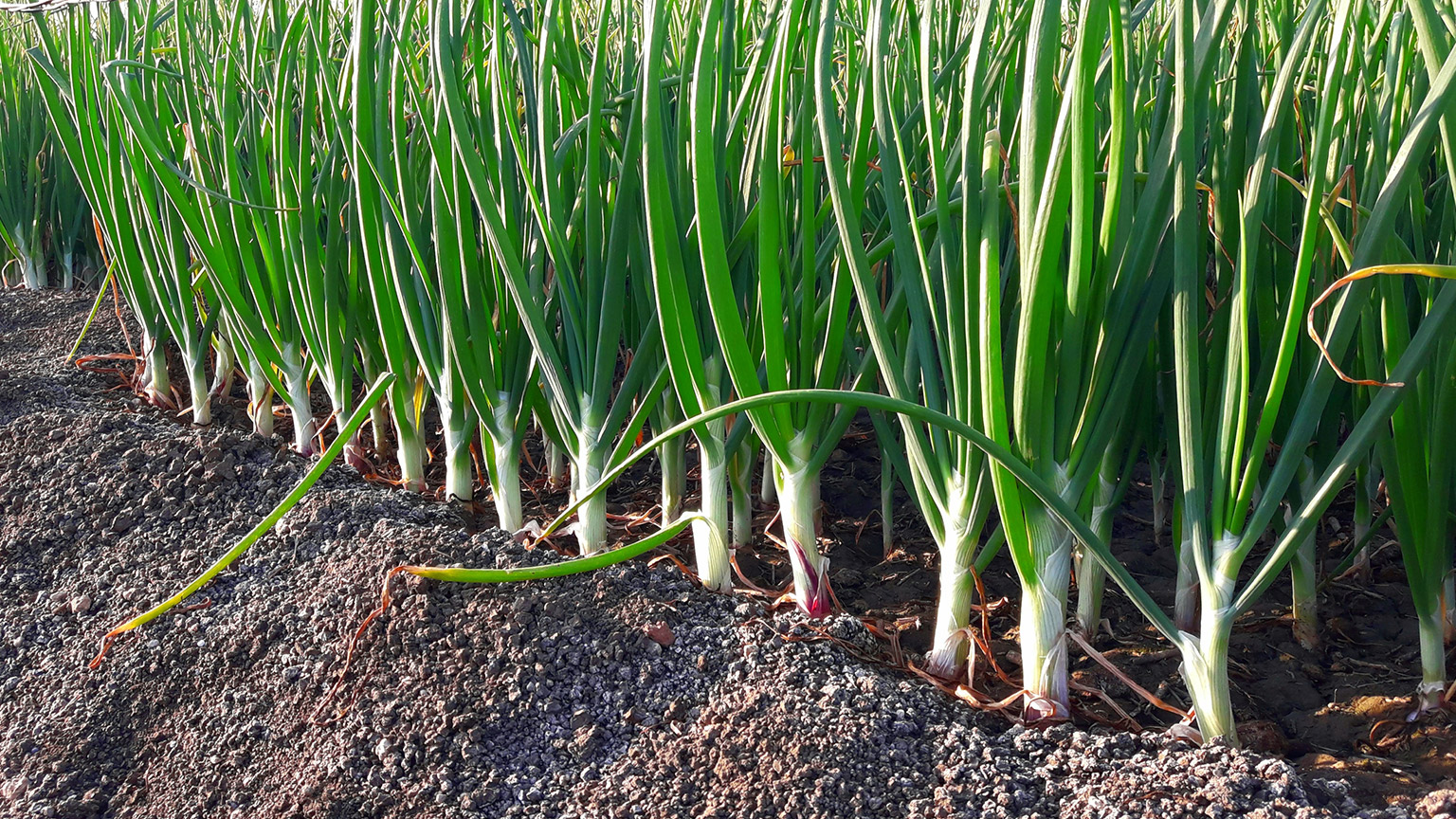
These spring onions, also called scallions and green onions (Allium fistulosum), are planted on mounded soil, which makes for good drainage.
An often overlooked part of soil water management is drainage. Making sure that you can get rid of excess soil water to avoid waterlogged soil. These onions have been mounded up to facilitate good drainage.

Different drainage systems are used to address different drainage problems. Before installing a drainage system, it's essential to know the problem and design a system to solve it.
The most common drainage problems for gardens are:
- Capping: Capping refers to the formation of a compacted layer or crust on the soil surface, often caused by raindrop impact or irrigation water. This compacted layer inhibits the infiltration of water into the soil, leading to reduced water penetration and increased surface runoff.
- Moisture retentive soils: Moisture retentive soils, such as clay soils or soils with high organic matter content, have small particle sizes and a high water-holding capacity. These soils can hold onto water for extended periods and exhibit slow percolation rates. The small pore spaces between soil particles in these soils restrict water movement, leading to reduced drainage.
- Compaction: This can contribute to both capping and moisture retention, as described above.
- Run-off from surrounding areas: When runoff from adjacent or uphill areas enters a particular site, it adds to the overall volume of water that needs to be drained. If the local soil has limited drainage capacity or is already saturated, the influx of additional water can overwhelm the soil's ability to absorb and drain it effectively.
- High water table: When the water table is close to the soil surface, the soil in the affected area is already saturated or near saturation. In such conditions, the soil has limited capacity to absorb additional water from rainfall or irrigation.
Activity – Drainage
What would you do in these scenarios?
Use this quiz to ensure you understand these tools and how the irrigation equipment would be used in the garden. Each question has only one answer, and the quiz will progress automatically.
Hydraulic conductivity test
We can measure how quickly our soil lets water in and how quickly it runs through it by performing a test called a hydraulic conductivity test. Hydraulic meaning to do with water or fluids and conductivity meaning how quickly something moves from one place to another.
There are many different ways to do this, but one of the easiest involves taking some soil core samples out of the ground and applying water to the tops of them. The diagram below is a visual explanation of the test.

To do this test, you’ll need:
- A section of strong, straight, pipe approximately 250mm long. This can be plastic, such as a water pipe or downpipe, or metal, but it needs to be the same length the whole way along.
- A permanent marker.
- A mallet, hatchet, or similar.
- A block of wood that is larger than the diameter of the pipe.
- A ruler.
- A cake cooling rack, or wire mail tray.
- A container to catch excess water.
- A bulldog clip or blu tac.
- A small kitchen knife.
- Paper towels or an old cloth.
- Two pairs of pliers (optional).
- A water source, ideally a hose with low flow, spray nozzle.
- A stopwatch or stopwatch phone app.
This test is best performed when the soil is already at field capacity – after a period of prolonged rain. If you need to do this when the soil is try, irrigate it for at least four hours before performing the test.
We’re going to take circular cores out of our soil that are 50mm thick/deep. Best practice is to take three cores from the same hole:
- Core one: 0-5cm deep
- Core two: 5-10cm deep
- Core three: 10-15cm deep.
The instructions below describe the steps if you’re using a single piece of pipe, but you can speed the test up if you have three sections of pipe. Then you can do the testing stage concurrently.
Preparing the equipment and site
- Place the wire rack on a hard level surface, outside, such as a deck, outdoor table or driveway.
- Use the ruler and permanent marker to measure and mark the pipe on the outside at 5cm, 10cm and 15cm from one end.
- Measure the internal diameter of your pipe in cm then divide by two to get the radius, for example: 8.8cm / 2 = 4.4cm
- Scrape back any grass or undecomposed plant material from the area you want to take your core samples from.
Taking a core sample
- Place the pipe on the soil surface and push down gently, so it’s sitting level on the soil.
- Place the block of wood on top and hold with one hand while tapping the block of wood with the mallet in your other hand. Don’t hit too hard or you can cause the soil in the pipe to crack and fall apart.
- Keep going until the 5cm mark on the pipe becomes level with the soil surface.
- Put the mallet and wood down and using both hands grab the top of the pipe using each hand to pinch the pipe wall on opposite sides.
- Move the pipe in a gentle rolling motion to loosen it from the surrounding soil as you pull up.
- Hopefully, the soil will be held tightly inside.
- If it falls apart, try taking a core from a different location.
- If the same happens, it’s fair to say that the soil at that depth is well draining.
- If you can’t lift the pipe out, try attaching two pairs of pliers and use them to pinch the pipe wall on opposite sides.
- If any soil sticks out the bottom of the pipe, cut it off using a knife.
- Take the core to the wire rack, being careful not to let the soil fall out.
Testing the core
- Sit the pipe with the core sample in it on the wire rack.
- Place the ruler inside the pipe so it sits on the top of the core at the edge and use the bulldog clip or blu tac to hold it upright against the side of the pipe.
- Use the hose to fill the pipe to the top, taking care to use a setting that gently applies water, so it doesn’t break up the core.
- When it’s full take a reading of the height of the water and then start your stopwatch.
- Let the water run through the core for long enough that the water level drops by a noticeable amount.
- At that point record the time that has passed and the water height.
- Write these down.
If you can’t fill your pipe because the water drains too quickly, we can call the drainage capacity “excess.”
Repeating the process
- Take the pipe back to the place you removed the core and press the core out next to the hole.
- Wash out the pipe and then dry the inside.
- Return to the location where you took the first core and place the pipe into the existing hole.
- Press it down so the 5cm mark is level with the surrounding ground.
- Follow the same process as before to extract another core that is 5cm deep. To do that you’ll want the 10cm measurement to be level with the ground before you lift it out.
- Take the core to your testing location then repeat with the (third) final core.
If you had a longer pipe, you could keep going, taking core samples from deeper depths. If you chose to do this, you’d only need to fill the pipe with water to a height of 20cm approx.
Use the navigation at the bottom of this slider to view some snapshots of the process.
Enter the results
Fortunately, the hard work has been done for us here.
- Go to the Sustainable Technologies page on Percolation test and click the Download Percolation test spreadsheet(.xlsx).
- Open the spreadsheet using Excel, Google Docs, or another spreadsheet application.
- Enter the radius of your pipe into the cell next to “Borehole radius (cm):”
- Fill in the cells next to Measurement 1, 2, and 3, using 1 for your first core (top 5cm of soil), 2 for the second core (5-10cm deep soil) and 3 for your final core (10-15cm deep soil).
- Observe the hydraulic conductivity rates specified in mm/hr in the end column.
Compare your results
- Use the table below to find the drainage class for each core.
- For our tests, both cores one and three drained so well we couldn’t fill the pipe; it drained too quickly, so both are considered “excess.”
- Core two had a drainage rate of 18.4mm/hr, so is classed as “moderate”.
| Hydraulic conductivity rate | Drainage class |
|---|---|
| Greater than 125mm/hr | Excess |
| 50-125mm/hr | Well |
| 15-50mm/hr | Moderate |
| 5-15mm/hr | Imperfect |
| 0.5-5mm/hr | Poor |
| Less than 0.5mm/hr | Very poor |
Take a look at your results. Does one core show a much slower percolation rate than the others?
If so, this is your limiting factor.
Take action
Where the top layer is the limiting factor, capping is an issue. Water is having a hard time making its way into the soil. If this is a garden bed, break up the capping by cultivating to a shallow depth to let water into the soil.
If the limiting layer is in the top 15cm, the issue is either moisture retentive soil – such as poor structure or too much organic matter, or compaction – such as a hard pan that can form regular tiling of wet soils. In the short term, press the tines of a garden fork into the soil as deep as you can and rock the fork back and forth. This creates channels that take surface water past the limiting layer into the faster draining soil below. Longer term, aim to improve the structure of the soil by increasing biological activity and encouraging deeper root growth.
If the limiting layer is deeper, it suggests that the subsoil is moisture retentive. You may need to install a drainage system (see the following subtopic).
If all layers have good percolation rates but water remains in the soil profile, this suggests a high water table. One option to combat this is to construct raised beds, which will provide a well-drained planting area for plants to grow, above the water table. Another more complex option is to install a water table control drainage system. This involves using pipe drains to move the water to a low point, such as a collection pit, and then pump the water up to a suitable outflow, such as a drainage ditch.
Now let’s look at a few of the most common types of drainage systems.

One of the benefits of in-ground raised beds is that they provide slopes to an otherwise flat surface to help with drainage.
There are a huge variety of drainage systems that aim to solve different drainage problems. The most common are:
- raised beds formed in line with fall of site
- interceptor drains
- pipe drains
- mole ploughing
- sand banding.
Raised beds
If you’re using raised beds (shown above), you’ve most likely already built drainage into your growing system.
If you’re using in-ground raised beds, excess water will naturally run off down into the pathways. If your site is sloping and you’ve oriented the beds to run downhill, even better!
If you’re using timber-sided raised beds and have filled them with good quality top soil or a mix of topsoil and compost, water should drain through fairly quickly.
Interceptor drains
Interceptor drains, also called cut-off drains, are installed at the bottom of a slope to stop water running down the slope and ponding on the level ground next to it. The purpose of an interceptor drain is to capture and redirect water before it reaches a specific area, such as a garden or house foundation, to prevent waterlogging, flooding, and damage to structures or crops.
The construction of an interceptor drain typically involves excavating a trench or channel in the ground. This may:
- have steep sides and be maintained so vegetation doesn’t grow in the channel (usually by spraying)
- be a gently sloped trough shape that is sown with grass seed – called a swale or swale drain. In some cases swales may contain drainage pipes or a permeable material under them, such as gravel.
The trench is sloped to facilitate water flow and is often connected to a network of pipes or an outlet for drainage.
When water flows toward the interceptor drain, it enters the trench or channel and is guided away from the protected area. The intercepted water is directed towards a suitable discharge point, such as a natural watercourse, a retention pond, or a drainage system.
Here is a sketch of that system.

Pipe drains
A pipe drain drainage system (drawing not to scale), often referred to simply as a pipe drain or subsurface drainage system, is a method of managing excess water in the soil by using a network of underground pipes.
The pipe drain system consists of a series of perforated or slotted pipes that are buried underground. Each continuous length of drainage pipe is called a run. These pipes are typically made of materials such as plastic, such as PVC. The pipes are installed in a pattern or layout that allows for efficient collection and removal of excess water from the soil. They are placed in trenches or ditches with a slope or gradient, which enables the water to flow naturally towards a desired outlet or discharge point.
When the water table or soil moisture level rises above a certain threshold, the excess water enters the perforations or slots in the pipes and is carried away through gravity due to the slope of the pipes.
Interceptor drains and pipe drains are considered primary drainage systems because they remove water from the target area to an outflow, such as a stream or drainage ditch.
Mole ploughing
Mole ploughing involves pulling a “bullet” through the soil to create a channel that water can easily flow into.
Ideally, mole ploughing will be carried out when the soil is hard and dry. In this situation the bullet and the shank that holds it in place cause the soil to crack as it moves through the profile. This forms a network of cracks that all act as pathways for water to flow down.
Mole ploughing is considered primary drainage when it links directly into an outflow. But it can also be used in conjunction with a pipe drain system, in which case it is considered secondary drainage. In this situation, the mole channels are created at an angle – usually 45 or 90 degrees – to the direction of the drainage pipe runs.
This video by AgAssist shows the formation of mole channels as primary drainage using a mole plough towed by a tractor.
Sand or gravel banding
Sand banding and gravel banding are similar techniques of creating secondary drainage by connecting the soil surface to the pipe drainage system using channels filled with either sand or gravel.
This is used extensively on sports fields and is carried out with specialised equipment that causes minimal damage to the playing surface.
The following video from Mexted Sports Turf shows the installation of gravel banding with a sand topping layer, as secondary drainage at Otaraua Park on the Kapiti Coast.
However, the same principle can be used for other areas and can act as primary drainage on sloping sites.
One option is to use a walk-behind chain trencher to dig the trenches and backfill them with gravel from a wheelbarrow (for small areas) a trailer, or even a concrete mixer truck (for larger areas).
WARNING!
Whenever trenching (whether using a spade or a mechanical trencher or excavator) always check for buried utility services. In Aotearoa beforeUdig describes themselves as a free online service that enables anyone undertaking excavation works to obtain information on the location of cables, pipes and other utility assets in and around any proposed dig site, helping to protect themselves and valuable assets during these works.
Go to www.beforeudig.co.nz for more information.
This covers most utility services but there may be other things, such as household roof water pipes that won’t show up on these reports. If you’re unsure, bring in an expert to scan your site. Just search for “locate underground services” and your location to find someone locally.
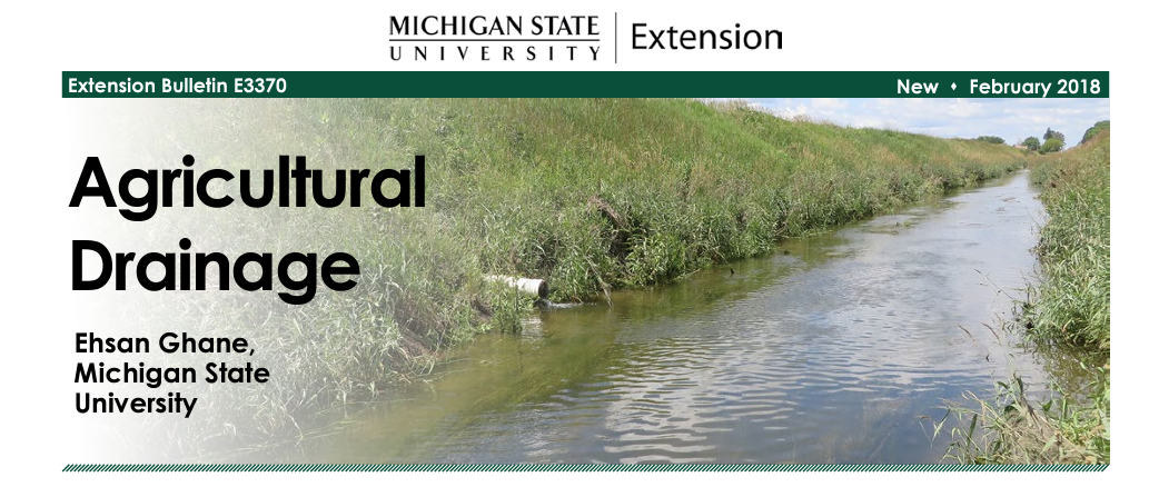
This bulletin, put out by Michigan State University's College of Agriculture and Natural Resources, offers a bit more detail about drainage solutions if you are interested in learning more.
But more importantly, it provides insight for growers in Michigan. Why is that useful for you here in New Zealand? You can view the considerations and information shared to get an idea of what you should be thinking about in your own water management tasks.

A shallow drainage installation showing a drainage pipe connected to a sump (collection pit). This looks ready to be backfilled with gravel and topped with sand or soil at ground level.
A pipe drainage system typically consists of several common components that work together to manage excess soil water. These components include:
Gravel or aggregate bedding: A layer of gravel or aggregate material is placed at the bottom of the trench as a bedding for the pipes. It provides support, prevents soil intrusion, and promotes water movement towards the pipes.
Geotextile fabric: Geotextile fabric is often used to line the trench walls or to encase the pipes. It helps prevent soil particles from entering the pipes, reducing the risk of clogging and maintaining the long-term functionality of the drainage system. Some drainage system designs specify the use of a geotextile sock – a tube of permeable geotextile fabric which can be pulled around the pipe as each section is installed.
Perforated or slotted pipes: These pipes form the main conduit for water drainage. They are made of materials such as plastic (e.g., PVC) or corrugated metal and are designed with perforations or slots along their length to allow water entry. The diameter and spacing of the perforations or slots can vary depending on the desired drainage capacity.
Cleanouts and inspection ports: Cleanouts or inspection ports are placed at intervals along the pipe drainage system to provide access for maintenance and inspection. These access points allow for the removal of any accumulated sediment or debris and help ensure the system operates efficiently.
Additionally, the system will direct the water to an outlet and may contain inlet structures such as catch basins or collection pits (sumps) installed at strategic locations to capture and direct surface water into the drainage system. They may include grates or filters to prevent debris from entering the pipes.
Activity – Drain
What would the gardener do?
Answer these four questions to test your understanding of drainage terms and tools. The quiz will progress automatically.