In Module 3 you will be introduced to architectural plans – site plans, floor plans, elevations, details, electrical plans, structural plans, and landscaping plans. There are a lot of different plans involved in any construction and installation! You will also need to understand legends, keys, specifications, symbols and scale. The content then introduces other types of electrical drawings - block diagrams, circuit diagrams, symbols, wiring diagrams, ladder diagrams.
You will learn about the different types of switches available and different wiring systems for lighting circuits. Your knowledge of circuit protection and electrical drawings will assist you in the design and construction of lighting circuits.
Next you will gain knowledge about the characteristics and applications of electrical cords and cables. This includes physical attributes such as construction, insulation, size and colour. Also included is cable selection based on external factors such as moisture, temperature and mechanical damage and internal factors like current carrying capacity and voltage drop. Sample calculations are given for selecting cables. Work through these carefully, making sure you understand where all the figures have come from.
Moving on from cable identification and selection, you will learn how to install and connect them to appliances. You will meet different classes of appliances, common cable support systems and most importantly - inspection and testing techniques. It is also helpful to know about moisture and fire barrier ratings for electric cable penetrations since you will be installing wiring systems in a variety of building materials.
The last section of content looks at basic lighting principles and luminaire installations. Examples are given of how to plan a simple lighting layout and you will be expected to complete a plan of your own.
With the support of your Tutor, you’ll review your work, and receive feedback towards set development and performance objectives.
Have fun!
| Credits | 24 |
| Learning Hours | 240 |
| Learning Outcome | 3.1 Document installation requirements for a variety of basic electrical plans. 3.2 Use circuit protection devices and fuses in basic electrical tasks 3.3 Select and install electrical cables and their accessories based on basic electrical job requirements 3.4 Plan, install, and troubleshoot cable support systems in a given electrical situation. 3.5 Join electrical cables for electrical equipment 3.6 Select and install basic lighting systems used in the electrical industry |
| Assessment | ELE03A ELE03B ELE03C ELE03D |
You are free to plan your studies in the way that works best for you, but we know that guidance on how to do this is also helpful. We suggest following way to navigate through the learning content over the next few weeks:
| Week 1 |
Topics:
|
| Week 2 |
Topics:
|
| Week 3 |
Topics:
|
| Week 4 |
Topics:
|
| Week 5 |
Topics:
|
| Week 6 |
Topics:
|
| Week 7 |
Topics:
|

What we're covering:
- Types of architectural drawings
- Interpreting architectural drawings
Architectural drawings are an essential part of building design and construction. These drawings provide detailed information about the layout, structure, and systems of a building, and are used by architects, engineers, builders, and other professionals to ensure that buildings are constructed safely, efficiently, and in compliance with building codes and regulations. There are several types of architectural drawings used in building design and construction, including:
- Site plans - show the layout of a property or site from an aerial view. They typically include details such as property boundaries; lot number; street address; building footprint; orientation; access; utility connections; landscaping; drainage etc.
- Floor plans - two-dimensional drawings showing the building layout from a bird's eye view.
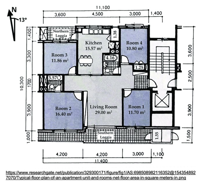
They typically show the location of walls, doors, windows, and other architectural features, as well as the locations of electrical fixtures, plumbing, and HVAC systems.
Floor plans are drawn to scale, with a ratio of the drawing to the actual size of the building, and may include additional information such as dimensions, labels, and notes.
- Elevations - two-dimensional drawings showing the exterior of a building from different angles. They provide information about the height and proportions of the building, as well as details such as windows, doors, and roofing.
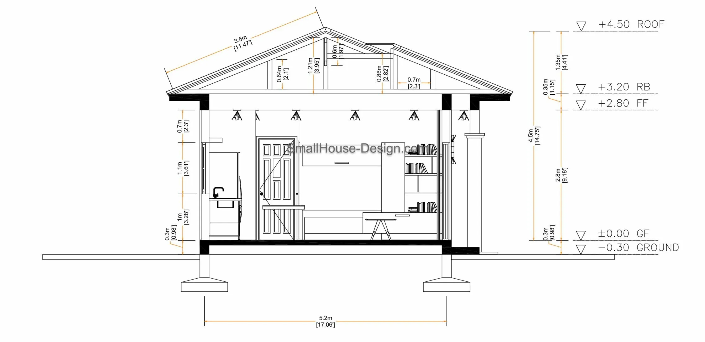
- Sectional Views - two-dimensional drawings showing a slice through the building from top to bottom, revealing details such as ceiling heights, stairways, and floor finishes.
- Details - two-dimensional drawings showing specific construction details in close-up, such as the connection between a wall and a roof or the installation of a window.
- Electrical plans - typically drawn on top of floor plans using symbols to show the layout of electrical wiring, fixtures, and equipment within the building.
- Structural plans - two-dimensional drawings showing the layout of structural components, such as columns, beams, and foundations.
- Landscaping plans - two-dimensional drawings showing the layout of exterior features such as gardens, paths, and water features.
Legends
Reading and interpreting architectural plans can be a complex task, especially for those who are not familiar with the symbols and abbreviations used in the drawings. This is where legends come in. A legend is a key or guide that accompanies an architectural plan and provides information about the different symbols, abbreviations, and colours used in the plan. The legend serves as a reference point for readers and helps them to understand the meaning of each symbol used in the plan. This includes symbols used to indicate doors, windows, walls, stairs, electrical outlets, plumbing fixtures, and more.
In addition to symbols, architectural plans may also use different colours to represent various features or elements. For example, blue may be used to indicate water supply lines, while red may be used to indicate fire protection systems.
Scale
Scale is another important aspect of architectural plans. It refers to the proportional relationship between the actual size of the building or structure and its representation on the plan. Scale is usually expressed as a fraction or ratio, for example, a scale of 1:100 means that one unit on the plan represents 100 units in real life. This can be interpreted as follows: 1 centimetre (0.01 metre) measured with a ruler on the plan would need to be multiplied by 100 to give the actual size of 1 metre. So, if you measured a wall length as 1 centimetre on a 1:200 scale plan, the actual length of the wall would be 2 metres.
The graphic scale may also include markings or divisions that indicate the length of a particular dimension or feature on the plan. The use of scale is crucial for accurately conveying the size and layout of the building and ensuring that all elements are properly sized and positioned.

The most common scales used in the construction industry include:
| Site plans | 1:1000 | 1:500 | 1:200 | |
| Floor plans | 1:200 | 1:100 | 1:50 | 1:20 |
| Elevations | 1:200 | 1:100 | 1:50 | 1:20 |
| Sectionals | 1:200 | 1:100 | 1:50 | 1:20 |
| Details | 1:10 | 1:5 | 1:2 | 1:1 (full size) |
Activity
Test your understanding of scale drawing by completing this worksheet.

What we're covering
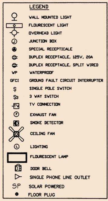
- Architectural symbols
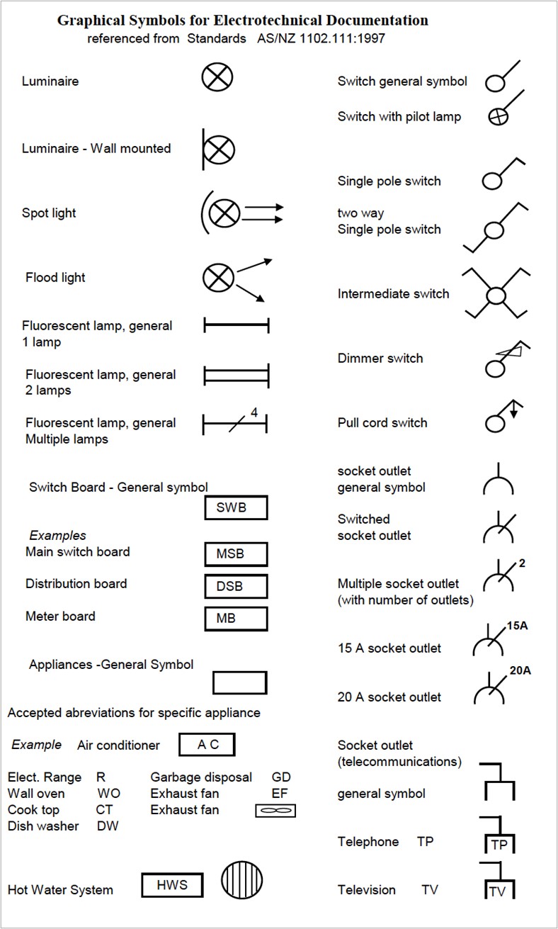
Electrical architectural symbols are used to represent the location and layout of electrical components within a building, such as electrical outlets, switches, light fixtures, and appliances. These symbols are standard and are used to identify and show the location of accessories and other equipment. They are called location symbols, and they are drawn superimposed on the architectural floor plan. The actual position of the equipment will depend on building and equipment construction, and the final positioning is left to the discretion of the installing electrician. Different symbols are used to represent lights, power points, and appliances, and they bear little, if any, resemblance to the items they represent.
The symbols on the following page are commonly used on electrical architectural plans. You will notice that some of these symbols differ from those used on circuit diagrams. Can you identify some that are different?
Activity
How would you interpret these symbols on an architectural plan?
Activity
Refer to the electrical plan below to answer the questions on this worksheet.
Forum
Complete the floor plan activity from today’s session and load in the class forum. Compare your tables to those of your classmates – discuss any discrepancies.

What we're covering:
- Types of electrical drawings
- Interpreting electrical drawings
Electrical drawings are essential documents used in the construction and installation of electrical systems. They provide a detailed representation of the electrical system and allow electricians to understand, install, and troubleshoot the system. Electrical drawings typically include several different kinds of diagrams, including block diagrams, circuit diagrams, wiring diagrams and ladder diagrams.
Block Diagrams
A block diagram is a simplified graphical representation of an electrical system. It uses a horizontal arrangement of labelled rectangular blocks, connected by lines with arrowheads, to show the direction of energy flow.
No detailed information is provided, as block diagrams are normally used in the development of circuit diagrams. They are useful for illustrating the overall function of a system and how different components are connected and interact, but they do not provide detailed information about individual components.
Block diagrams help in diagnostics by indicating the relationship of each subsystem to the next and are used to describe the sequence of circuit operations.

Circuit Diagrams
A circuit diagram, also referred to as a ‘schematic diagram’, is a detailed diagram intended to describe the operation of a circuit. Circuit diagram can be very complex and for a piece of equipment may in fact contain several circuits. All circuit diagrams contain symbols representing components, or items of equipment, interconnected by lines representing conductors. The layout and position of the diagram do not necessarily reflect the physical layout of the wiring and equipment.
The primary purpose of circuit diagrams is to help in designing or developing an original circuit from a block diagram, to determine the operation of a circuit, and to assist in locating a fault.

The distinction between a block diagram and a circuit diagram, are:
- Block diagrams provide an overview of the operation of a circuit or system.
- Circuit diagrams provide detailed information on the operation of a circuit or system.
Standard Electrical Symbols
A drawing symbol is a graphical representation of a component or item to be included in a diagram. The use of symbols is a convenient means of representing items in a diagram as this allows:
- Items to be included in a diagram in a simplified form (a symbol is simpler to draw than the actual item itself).
- Items, similar in appearance but differing in function can be easily distinguished in a diagram.
There is a need for a standard to be adopted when representing components in a circuit, wiring or block diagram. The use of standard symbols allows communication of ideas between individuals or organisations without the need for lengthy documentation accompanying every diagram.
The standard adopted in New Zealand and Australia for drawing symbols is the ISO (International Standards Organisation) standard. These symbols are laid out in AS/NZS 1102. 103:1997 Graphical symbols for electrotechnical documentation. The standard is based on but not equivalent to, and reproduced from, IEC 617-3s.
Like architectural drawings, standard graphical symbols are used on electrical drawings to represent specific items such as switches, conductors, relays, lights, etc.
Using standard symbols ensures that everyone using the drawings interprets them correctly.
AS/NZS 1102:101 to 110:1997 Graphical Symbols for Electrotechnology Documentation, which is aligned to International Standards, applies to the symbols used on electrical drawings. Standards have change over time however and not all countries use the International Standards, so you will encounter variations in symbols.
Activity
Refer to AS/NZS 1102 (or another source applicable in New Zealand) to complete the following table of commonly used electrical circuit symbols:
To accurately read and obtain information from an electrical drawing, they must adhere to certain conventions and principles. They should flow consistently as either as a “horizontal drawing” or a “vertical drawing”. “Horizontal drawings” have the power supply flowing from left-to-right and the sequence of control operation from top-to-bottom. In “vertical drawings” the power supply flows from top-to-bottom and the control sequence of operation from left-to-right.

Wiring Diagrams
A wiring diagram is a detailed diagram showing the way a circuit or system is wired and assembled. It shows the relative position of each component, the paths taken by wires, the junctions, or terminals where wires are connected, and the sequence of operations of switches, relays, or other control devices. 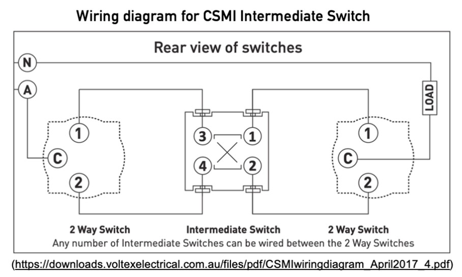
Components are typically drawn in a simplified way the outline and external connections (terminals) are shown. Several conductors may be shown as being connected to a given terminal in a wiring diagram however in a circuit diagram only one conductor appears to terminate at any given terminal.
Wiring diagrams are preferred over circuit diagrams because of the greater detail of the information they show. They include terminal identification numbers that enable proper wiring and show the exact location of all components and wiring. They are commonly used for the installation of luminaires and appliances, wiring of switchboards and control panels, and verification and fault-finding in a modified circuit.
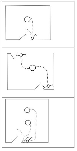
Carefully study the wiring diagrams shown in Figures 3, 4 and 5 of NZECP 51:2004. Figure 3 illustrates a one-way lighting circuit, Figure 4 a two-way lighting circuit and Figure 5 shows a socket-outlet circuit.
Activity
Converting Circuit Diagrams to Wiring Diagrams
This process is necessary to allow a circuit diagram to be converted to a form that will allow assembly and wiring of the equipment. Although simple circuits may not require this conversion, it is crucial for more complex circuits.
The conversion of the circuit diagram into a wiring diagram assists efficient layout and routing of cables and enables the selection of cable types in some cases. On the other hand, wiring a circuit directly from a circuit diagram can lead to problems such as cable waste, unnecessarily large cable looms, and an excessive number of conductors terminating at a given terminal.
For basic circuits, it is sufficient to number the terminals on the components, but for more complex circuits a numbering system identifying both the terminals and conductors is necessary.
Activity
Convert the circuit diagram below into a wiring diagram. Draw it on a piece of paper and show it to your tutor the next time you are on campus.

Ladder Diagrams
Ladder diagrams are specialised circuit diagrams commonly used to illustrate industrial control logic systems. They are called ladder diagrams because they mimic a ladder, with two vertical rails representing the two sides of a supply circuit (active and neutral), and as many "rungs" (horizontal lines) as there are to represent control circuits. With ladder diagrams no attempt is made to show the actual physical locations and the emphasis is on clearly showing how the control is exercised.
This diagram shows a circuit for switching an electric motor on or off.

The circuit can be redrawn as a ladder diagram. The power lines, or rails form the vertical sides of a ladder with the horizontal rungs showing the control portion of the circuit.


What we're covering:
- Available software to use for electrical drawing.
- Using specific types of electrical drawing software.
Circuit diagrams and wiring diagrams may be produced manually or electronically, depending on the complexity and accuracy required. There are many software tools available to create circuit and wiring diagrams including SmartDraw, Edraw, AutoCAD Electrical, SolidWorks Electrical, TinyCAD, and Visio. Check with your tutor about recommendations for a suitable programme to use.
In the following activity, you will be using SmartDraw to create a circuit diagram and a wiring diagram. Start by watching the tutorial found here:
Now visit the SmartDraw site where you will find more information and written instructions for creating block diagrams, circuit diagrams and wiring diagrams, as well as floor plans. Familiarise yourself with each.
Activity
Drawing a circuit diagram and a wiring diagram.
This circuit is a simple example of a basic electronic circuit. When the switch is closed, current flows through the resistor and the LED, causing it to light up. When the switch is open, no current flows and the LED remains off.
- Begin by opening the SmartDraw electrical drawing software on your computer.
- Click on the Engineering & CAD category then Circuit Panels in SmartDraw's Template Browser to find a circuit diagram template.
- Open the template called "Basic Electrical". (You should begin with a blank page.)
- Create a new drawing and start by adding the power source (9V battery) to the top of the page.
- Connect the power source to a switch (SPST) using a line.
- Add a resistor (220 ohm) to the drawing and connect it to the switch using a line. The resistor should be placed below the switch.
- Add an LED (5mm, red) to the drawing and connect it to the resistor using a line. The LED should be placed below the resistor.
- Add labels to the symbols and wires to indicate their function and identify them.
- Check your diagram for errors or inconsistencies, such as missing connections or incorrect symbols.
- Customise the appearance of your diagram by changing the colour and thickness of the lines, adding a background or grid, or choosing a different theme from the options provided.
- Once you have completed the circuit diagram, create a wiring diagram using the same components and connections. The wiring diagram should show the physical layout of the wiring, including any junction boxes or conduit used.
- When both diagrams are complete, review them to ensure that they match the instructions provided and that they accurately represent the circuit and wiring layout.
- Save your work and submit a screenshot, PDF or image file of your completed diagrams to the class forum for discussion.
Activity
Drawing a circuit diagram and a wiring diagram.
This circuit is a simple example of a basic DC voltage regulator. The diode and capacitor act as a voltage regulator to ensure a constant voltage supply to the LED. The resistor is used to limit the current flowing through the LED and the capacitor stores the energy needed to keep the LED lit even when the input voltage fluctuates.
- Begin by opening the SmartDraw electrical drawing software on your computer.
- Create a new drawing and start by adding the power source (12V DC) to the top of the page.
- Add a resistor (1k ohm) to the drawing and connect it to the positive terminal of the power source using a line. The resistor should be placed below the power source.
- Add a diode (1N4004) to the drawing and connect it to the negative terminal of the power source using a line. The diode should be placed below the resistor.
- Add a capacitor (100uF, 25V) to the drawing and connect it to the anode of the diode using a line. The capacitor should be placed below the diode.
- Add an LED (5mm, blue) to the drawing and connect it to the cathode of the diode using a line. The LED should be placed below the capacitor.
- Once you have completed the circuit diagram, create a wiring diagram using the same components and connections. The wiring diagram should show the physical layout of the wiring, including any junction boxes or conduit used.
- Add labels to the symbols and wires to indicate their function and identify them.
- Check your diagram for errors or inconsistencies, such as missing connections or incorrect symbols.
- Customise the appearance of your diagram by changing the colour and thickness of the lines, adding a background or grid, or choosing a different theme from the options provided.
- Once you have completed the circuit diagram, create a wiring diagram using the same components and connections. The wiring diagram should show the physical layout of the wiring, including any junction boxes or conduit used.
- When both diagrams are complete, review them to ensure that they match the instructions provided and that they accurately represent the circuit and wiring layout.
- Save your work and submit a screenshot, PDF, or image file of your completed diagrams to the class forum for discussion.
Self-directed Learning
Complete your diagrams, post to the class forums (electrical circuit forum, DC voltage regulator forum), and compare with others. Have you all interpreted the instructions in the same way?

What we're covering:
- Components of an electrical plan
In the previous sessions we learnt how block diagrams, circuit diagrams, wiring diagrams and ladder diagrams all contribute to the overall electrical plan.
Let’s look at the various components of an electrical plan.
Layout and location
The plan typically includes a diagrammatic representation of the layout and location of electrical equipment, such as main and auxiliary switchboards, distribution boards, power outlets, light fittings, appliances (such as air conditioning units, hot water systems, and ranges), telephone and television outlets, and data and video outlets. The plan may also include information on the location of electrical conduit, cable trays, and other components.
The NZ Building Code requires the electrical, or energy services, plan to show the location of electrical, gas, communications, and mechanical ventilation fixtures, such as hot water supply, heat pumps, meter-boards, and smoke detectors.
Scales
As previously mentioned, scales are used to represent the physical size of the building and the location of the electrical system components in relation to each other. Electrical plans must be drawn to scale, with the scale clearly indicated on the plan. The scale should be appropriate for the size of the building or site and should allow for accurate placement of all electrical system components.
Electrical symbols
Electrical symbols are used on electrical wiring plans in order to show the location, control point(s), and type of electrical devices required at those locations. These symbols, which are drawn on top of the floor plan, show lighting outlets, power points or socket outlets, special purpose outlets, circuit breakers, fan outlets and switches. The symbols are standardised and based on the IEC standards.
Dashed lines are drawn between the symbols to denote which switches control specific lights or receptacles.
Legends
Symbols and abbreviations may vary from plan to plan which can be confusing! Legends are an essential component of electrical plans, providing key information about the symbols and abbreviations used, ensuring the plan is clear and easily understood by everyone involved.
Plan legends are typically placed near the bottom or side of the electrical plan, and they are commonly organised by the type of symbol or abbreviation. The legend must be easily readable and distinguishable from the other information on the plan.
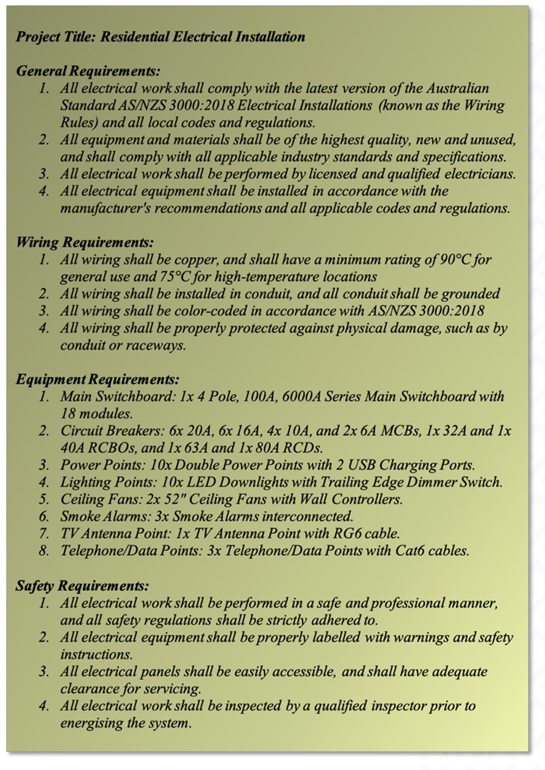
Plan Specifications
Plan specifications provide detailed information about the type of wiring, equipment ratings, installation methods, and safety requirements for the electrical work. They also provide information on any special requirements, such as energy efficiency or environmental concerns.
Plan specifications help ensure the system is installed correctly and meets all relevant codes and regulations. They are often included in the contract documents and must be followed by the installer to ensure compliance with regulations.
Activity
Answer the questions on this worksheet about plans and specifications. You will use this worksheet to complete the following activity as well.
Load calculations
The plan may include load calculations that show the expected electrical load on the installation. Load calculations consider factors such as the type and quantity of lighting, appliances, HVAC systems, and other electrical equipment that will be used within the building.
This information is used to ensure that the installation is designed and installed correctly and can handle the maximum expected electrical load. Overloaded circuits can cause damage to electrical equipment and fires, posing a safety hazard to occupants.
Load calculations will impact on the number of circuits required for an electrical installation. The total electrical load of a building must be distributed across multiple circuits to prevent overloading, and the number of circuits required will depend on the total electrical load and the electrical code requirements. For example, if the total electrical load of a building is 100 amps, and the electrical code requires each circuit to be limited to a maximum of 20 amps, then a minimum of 5 circuits would be needed to distribute the electrical load. (Factors such as the type and number of electrical devices and building layout also impact the number of circuits required.)
Regulatory compliance
The plan may include information on regulatory compliance, such as compliance with the Wiring Rules, the Building Code, and other relevant standards and regulations.
Labelling Techniques
Labelling techniques may be included on the electrical plan to provide information about the electrical systems and devices on the electrical plans. Some of the commonly used labelling techniques are:
- Circuit Identification: Each circuit on the electrical plan is labelled with a unique identification number or letter which provides information about its specifications, such as the voltage rating, current rating, and conductor size.
- Device Identification: Each device on the electrical plan is labelled with a unique identification number or letter which identifies the device and provides information about its specifications, such as the type, rating, and location.
- Panel Schedules: Panel schedules are used to provide information about the circuit breakers and their corresponding loads. These schedules include the circuit identification, device identification, and other specifications, such as the voltage, current, and power ratings.
- Earth: As you already know, earth is a reference point in an electrical circuit used for safety purposes. Typically, a metal rod or plate buried in the earth, it is connected to the electrical system to provide a safe path for electric current in case of a fault.
Activity
Refer to this diagram about the electrical plan to answer the questions in the worksheet you downloaded for the previous activity.

What we're covering:
- residential floor plans
This lesson builds on the content of the previous lesson.
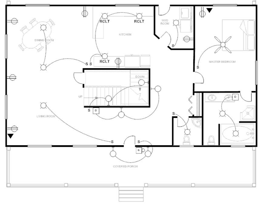
Activity
Interpret the electrical floor plan for the residential dwelling and then answer the questions in this worksheet.
- Use this worksheet for the following activity as well. You can wait to post in the forum until you have done both or post the first, and then edit the post and upload a new version of the worksheet when you complete the questions.
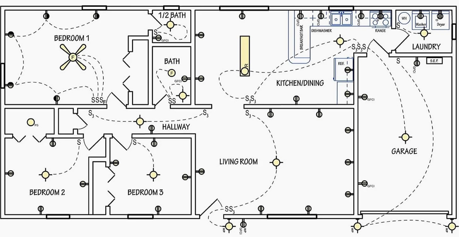
- The electrical floor plan does not include a legend. Create a legend suitable for this plan.
- Prepare a plan specification. Write your answers in the table provided. Post your table on the class forum to check whether you correctly identified all the electrical devices and their quantities.
Activity
Answer the following questions regarding electrical plans. There is space for you to do this on the worksheet you downloaded for the previous activity. Make sure you cite any references you use to find your answers. AS/NZS3000:2018, NZECP 51:2004 etc.
- What is the minimum height that a switchboard must be installed above a floor according to?
- What are two places that switchboards are not allowed to be located?
- What is the minimum number of lighting circuits required for a domestic installation?
- Name two domestic appliances require their own circuit.
- What distance must a cable in your electrical installation be placed from a telecommunications circuit, or a circuit operating at a voltage different from 230V?
- What is the maximum number of 10A double power outlets per circuit allowed in areas other than kitchens and laundries?
- What is the maximum number of 10A double power outlets per circuit allowed in kitchens and laundries?
- What is the minimum height a socket-outlet must be installed above the floor of a bathroom or laundry?
- Which types of fixed electrical equipment in residential installations require RCD protection?
- What is the maximum rated residual current that RCDs protecting these circuits?
- Update or create your forum post from the link in step 2 above.
Activity
Imagine you are designing the electrical plan for a commercial building. Investigate the requirements for the location and type of emergency lighting in a commercial building according to NZ regulations. Summarise your findings as bullet points on the class forum and compare to your findings to others in the group.