Welcome to the final course of your Level 3 Certificate in Electrical Pre-Trade! In this course on Electrical Machines and Transformers, we will cover a range of fascinating topics that will expand your understanding of electrical systems.
We'll begin by exploring the fundamental concepts of capacitors and inductors and their significance in the world of electrical machines and transformers. These concepts are crucial for grasping the inner workings of electrical systems.
Next, we'll dive into semiconductor theory and delve into the function, operation, and applications of common electronic components. You'll learn about safe handling and testing of electronic components, as well as the skill of soldering and desoldering them onto printed circuit boards.
We'll then shift our focus to single-phase transformers, where you'll gain knowledge about their construction, operating principles, key components, measurements, and safety requirements. By the end of this section, you'll have a solid understanding of different types of transformers and their roles in electrical systems.
Finally, we will explore the wiring, testing, running, and reversing of single-phase motors. You'll discover how these motors are connected and learn about their construction and operating principles. This knowledge will equip you with practical skills for working with single-phase motors.
Throughout the course, you'll have the opportunity to practice the practical aspects of these topics during face-to-face sessions with your tutor. These sessions will provide valuable guidance and hands-on experience to reinforce your learning.
This online resource will enhance your lessons through daily study materials and self-directed learning, helping you prepare for assessments and deepen your understanding. Your tutor will provide support, feedback, and guidance as we embark on an engaging learning journey together. Let's get started!
| Credits | 12 |
| Learning Hours | 120 |
| Learning Outcome |
5.1 Apply knowledge of capacitance, inductance, power factor and power factor correction to basic electrical tasks 5.2 Use single-phase and three-phase transformers in basic electrical tasks 5.3 Use single phase and three phase rotating machines in basic electrical tasks 5.4 Apply knowledge of legislation, electrical theory, and electrical practice for working in electrical trades |
| Assessment | 05A 05B 05C Capstone Assessment (Assessed Externally) |
You are free to plan your studies in the way that works best for you, but we know that guidance on how to do this is also helpful. We suggest following way to navigate through the learning content over the next few weeks:
| Week 1 | Topic 1, Topic 2 |
| Week 2 | Topic 3 |
| Week 3 | Topic 3 |

What we're covering:
- Definition
- Formula for Calculating Capacitance
- Capacitance Units
- Connecting Capacitors
- Capacitator Ratings
- Capacitive Resistance
Capacitator Definition
A capacitor is an electronic component that stores and releases electrical energy. It consists of two conductive plates in close proximity to each other, separated by an insulating material called a dielectric. When a DC voltage is applied across the plates, the capacitor accumulates equal and opposite electric charges on each plate. One plate becomes negatively charged and the other becomes positively charged.
This charge accumulation creates an electric field between the plates, storing energy in the form of electrostatic potential. The insulating dielectric material prevents the flow of direct current between the plates, allowing the charge to be retained.
When the power source is removed, the charged plates retain their respective charges, with the potential energy stored in the electric field. The capacitor can then be connected to a load, such as a camera flash bulb or any other electrical device. Upon connection, the capacitor releases all of its stored energy rapidly into the load, providing a sudden burst of power.
Capacitors can also be used in AC circuits, where they exhibit frequency-dependent behaviour, storing and releasing energy as the AC signal changes polarity. They are widely used in various electronic circuits and applications, such as filtering, timing, energy storage, power supply stabilization, and signal coupling. The specific type of capacitor chosen depends on factors like required capacitance value, voltage rating, size constraints, and other application-specific requirements.

Capacitance
The capacitance of a capacitor is a measure of its ability to store charge for a given voltage. It is determined by the physical characteristics of the capacitor, such as the surface area of the plates, the distance between them, and the properties of the dielectric material.
Formula
The mathematical formula for calculating capacitance (symbol C) is expressed as:
Where:
- C = capacitance in farads (F)
- Q = electrical charge in coulombs (C)
- V = potential difference in volts (V)
What electrical symbol do we use to represent a capacitator?
Capacitance Units
The unit of capacitance is the Farad (F), named after Michael Faraday. Farads are quite large for most practical applications. Instead, capacitors are commonly measured in subunits such as microfarads (μF), nanofarads (nF), and picofarads (pF). One farad is the amount of capacitance required to store one coulomb of charge when the voltage across the capacitor is one volt. The larger the capacitance, the more charge the capacitor can store.
- The microfarad is equal to one millionth of a Farad ^ (-6) F) and is commonly used to express capacitance values in practical applications.
- The nanofarad is equal to one billionth of a Farad (10^ (-9) F) and is frequently used to represent smaller capacitance values, especially in electronics.
- The picofarad is equal to one trillionth of a Farad (10^ (-12) F) is the smallest commonly used unit for capacitance and is often used to measure small capacitance values in integrated circuits and high-frequency applications.
Activity
Complete the table by dragging and dropping the numbers into their correct places in the table.
Factors Affecting Capacitance
The capacitance of a capacitor depends on three factors:
- the area of the plates
- the distance between the plates
- and the dielectric material between the plates.
Capacitance is directly proportional to the area of the plates and the dielectric constant of the material, but inversely proportional to the distance between the plates.
Activity
Complete the sentences with the correct missing words
Connecting Capacitors in a Circuit
Capacitors can be connected in series or parallel configurations, just like other components. The way capacitors are connected affects their overall capacitance value.
- Series Connection: When capacitors are connected in series, the effective plate separation increases since there are now two dielectrics between the first and last plate. The increased distance between these plates decreases overall capacitance. The voltage across each capacitor in a series connection is inversely proportional to the capacitance. The smallest capacitance will have the highest voltage, while the largest capacitance will have the lowest voltage.
- Parallel Connection: When capacitors are connected in parallel, the overall capacitance increases. This is because the effective plate area is increased. In a parallel connection, the supply voltage is applied to all capacitors, and each capacitor has the same potential across its plates. If a 20V supply voltage is applied to two capacitors in parallel, both capacitors would have 20V across their plates.
Equivalent Capacitance (Ceq):
Where:
- Ceq = equivalence inductance
- C1 = inductance of inductor 1
- C2 = inductance of inductor 2
- C3 = inductance of inductor 3
Remember to consider the appropriate connections and configurations when using capacitors in electrical circuits.
Activity
Select the correct answer to each question from the choices below.
Capacitor ratings
The capacitance value alone does not provide a complete picture of a capacitor's performance and suitability for a specific application. Capacitors are rated for various parameters that are important for their proper selection and usage including:
- Voltage Rating: This indicates the maximum voltage that a capacitor can withstand without experiencing electrical breakdown. It is crucial to choose a capacitor with a voltage rating higher than the maximum voltage in the circuit to avoid damage or failure.
- Current Rating: The current rating specifies the maximum current that a capacitor can safely carry without overheating or causing excessive internal heating. It ensures that the capacitor can handle the current demands of the circuit without being damaged.
- Temperature Coefficient: The temperature coefficient reflects how the capacitance of a capacitor changes with temperature variations. It provides information about the stability of the capacitance value over a range of temperatures. A lower temperature coefficient signifies better stability.
- ESR (Equivalent Series Resistance): ESR represents the internal resistance of a capacitor. It impacts the capacitor's performance, particularly in terms of energy dissipation and power handling capabilities. Lower ESR values indicate better performance and efficiency.
The usable capacitance of a capacitor may vary from its rated value due to various factors such as temperature, humidity, voltage, frequency, age, and mechanical factors. When choosing a capacitor for a specific application, it is important to consider its ratings for these factors. Another important consideration is the tolerance of the capacitor, which indicates how closely the actual capacitance may deviate from the stated value. Common tolerance codes include ±20% (M), ±10% (K), ±5% (J), ±2.5% (H), ±2% (G), and ±1% (F)
Activity
Select the correct answer to each question from the choices below.
Capacitive Reactance
Capacitive reactance is a property of capacitors in AC circuits. It is a measure of how much opposition or resistance a capacitor offers to the flow of alternating current. Capacitive reactance is inversely proportional to the frequency of the AC signal - the higher the frequency, the lower the capacitive reactance, and vice versa.
Capacitive reactance is represented by the symbol Xc and is measured in ohms (Ω).
The formula for calculating capacitive reactance is:
Xc = 1 / (2πfC)
Where:
- Xc is the capacitive reactance in ohms (Ω).
- π is the mathematical constant pi (approx. 3.14159)
- f is the frequency of the AC signal in hertz (Hz)
- C is the capacitance of the capacitor in farads (F)
Example 1
Consider a capacitor with a capacitance of 10 microfarads (μF) connected to an AC circuit with a frequency of 50Hz. Calculate the capacitive reactance.
Solution
Given: C=10 μF = 10x10∧(-6)F, f = 50Hz
Using the formula: Xc = 1/(2πfC)
Xc = 1/(2 x 3.14159 x 50 x 10∧(-6))
Xc ≈ 318.31 ohms (Ω)
Example 2
If the frequency of an AC signal is doubled while the capacitance remains the same, how does the capacitive reactance change?
Solution
Let's assume the initial capacitive reactance is Xc1, and after doubling the frequency, the new capacitive reactance is Xc2.
From the formula Xc = 1/(2πfC), we see capacitive reactance is inversely proportional to frequency. Therefore if frequency is doubled, capacitive reactance will be halved. In other words, Xc2 = Xc1/2.

What we're covering:
- Types of capacitators
- Applications
- Safety requirements
- Connecting capacitators
Types of capacitors
Capacitors can be divided into two main categories: fixed capacitors and variable capacitors.
Fixed Capacitors: Fixed capacitors have a specific capacitance value that cannot be changed. They are further classified as:
- Polarised Capacitors: Used in DC applications, these capacitors have polarity and must be connected with the correct orientation.
- Non-polarised Capacitors: Suitable for both AC and DC applications, these capacitors do not have polarity restrictions.
Variable Capacitors: Variable capacitors allow the user to adjust the capacitance value. This is achieved by changing the plate area or altering the distance between the plates.
The figure above (Image via Würth Elektronik) further summarises the different capacitor types currently available.
Let’s look at some of these different types of capacitors.
Film Capacitors
Film capacitors are made of a thin plastic film sandwiched between two conductive plates. They are reliable, precise, and have low dissipation. They can withstand high voltages and have long shelf and service lives. Film capacitors are used in audio circuits, power electronics devices, safety capacitors, electromagnetic interference suppression, fluorescent light ballasts, and snubber capacitors.

Ceramic capacitors
Ceramic capacitors are small, inexpensive, and fast-responding capacitors made of ceramic. They are commonly used in low-power and high-frequency applications. Class 1 ceramic capacitors are highly stable and ideal for precise applications, while Class 2 ceramic capacitors are cost-effective and suitable for general-purpose use.

Electrolytic capacitors
Electrolytic capacitors are widely used in power supply circuits and high-power applications. They have a higher capacitance than other capacitors and do not require tight tolerances or AC polarisation. However, they have some drawbacks, such as large leakage currents, variable capacitance values, and a limited lifetime. It is important to connect them with the correct polarity to avoid overheating or explosion.

Supercapacitors
Supercapacitors are a type of capacitor that can store more energy than regular capacitors and charge and discharge much faster. They are replacing batteries in some applications, such as cars and cameras, due to their fast charging and discharging speeds. However, they have a lower energy density than batteries, which means they can store less energy for a given size or weight. As a result, they may not be as suitable for applications that require long-term energy storage or extended operation without recharging. They also tend to be more expensive than batteries.

Mica capacitors
Mica capacitors are a type of capacitor that uses mica as the dielectric material. They are commonly used in high-frequency applications where stability and precision are important. Mica capacitors are small, reliable, and stable, with low loss and high precision. However, they are bulky and expensive.

Glass capacitors
Glass capacitors are special capacitors used in RF circuits. They offer low temperature sensitivity, zero aging rate, minimal noise, and very low loss. They can handle high RF currents and operate at high temperatures, up to around 200°C.
Feed-through capacitors
Feed-through capacitors are used in electronic circuits to filter unwanted signals and noise. They have a ceramic or ferrite core and pass desired signals through the centre while shunting unwanted signals to the ground. This reduces electromagnetic interference (EMI) and maintains signal integrity. Feed-through capacitors are commonly used in power supplies, data communication systems, and sensitive electronic equipment.
CAPACITOR APPLICATIONS
- Filtering: Capacitors are commonly employed to filter out unwanted frequencies from signals. They are connected in conjunction with other components to selectively allow certain frequencies to pass while blocking others. This application is vital in signal processing and communication systems. For example, capacitors are used in audio amplifiers to filter out noise and improve sound quality. They are also used in radio receivers to filter out unwanted signals and improve reception.
- Oscillation: Capacitors play a crucial role in oscillating signals within a circuit. They are often used in conjunction with resistors and inductors to create oscillators that generate continuous waveforms. Oscillators are utilised in applications such as generating clock signals and producing audio frequencies. For example, capacitors are used in the power supplies of electronic devices to create a stable and regulated output voltage. They are also used in electronic clocks and watches to generate the timing signals.
- Amplification: Capacitors are integral to amplification circuits. They are connected in series between stages to block direct current (DC) while allowing alternating current (AC) signals to pass through. This coupling arrangement helps prevent interference between stages and facilitates signal amplification. For example, capacitors are used in microphones to amplify the sound signal before it is sent to an amplifier. They are also used in amplifiers to increase the volume of audio signals.
- Smoothing: Smoothing capacitors, also known as filters, are connected across the output of AC-to-DC rectifiers. They are used to reduce small variations in the rectified direct current, commonly referred to as ripple. The capacitor stores energy during the high points of the ripple and releases it during the low points, resulting in a smoother and more stable output. For example, capacitors are used in power supplies to provide a smooth and consistent DC voltage to electronic devices. They are also used in audio amplifiers to smooth out the rectified signal and improve sound quality.
- Contact Protection: Capacitors can be used to protect switch contacts in inductive circuits. When a switch is opened or closed, the rapid change in current can cause arcing and sparking at the contacts, leading to contact damage and radio interference. A capacitor connected in parallel with the switch can help to mitigate these issues. When the switch is closed, the capacitor is shorted out and discharged. When the switch is opened, the capacitor absorbs the energy released by the inductor, reducing the available energy for arcing and preventing contact burning. For example, capacitors are used in high-power machines to protect the switch contacts from arcing.
- Flash photography: Capacitors are used to store energy that is then released to power the flashbulb. The capacitor is charged up by the battery in the camera. When the shutter button is pressed, the capacitor discharges, providing a brief burst of high-current electricity to the flashbulb. This causes the flashbulb to heat up and emit a bright flash of light.
- Tuning circuits: Capacitors are used in conjunction with inductors to create tuned circuits that resonate at a specific frequency. These circuits are used in radios, televisions, and other electronic devices. The capacitor and inductor form a resonant circuit, which has a natural frequency at which it oscillates. This frequency can be tuned by adjusting the value of the capacitor or inductor.
- Digital circuits: Capacitors are used in digital circuits to store data and to perform logic operations. In digital circuits, information is represented by binary digits, or bits. A bit can be either a 0 or a 1. Capacitors can be used to store bits of information by charging or discharging them. For example, a capacitor can be used to store a single bit of information in a computer memory cell.
Capacitors are versatile and essential components in a wide range of electronic devices. Their ability to store and release electrical energy makes them ideal for a variety of applications. They can be found in the following industries:
- Power Supply: Capacitors are used in power supply circuits to store energy and filter noise.
- Renewable Energy: Capacitors are used in solar inverters, battery banks, and supercapacitors.
- Automotive: Capacitors are used in engine control units, lighting systems, and motor control circuits.
- Industrial: Capacitors are used for power factor correction, motor starting, and harmonic filtering.
- Telecommunications: Capacitors are used in data centres, routers, switches, and antennas.
- Other: Capacitors are used in medical equipment, aerospace and defence systems, transportation systems, and lighting technologies.
Safety requirements and handling techniques for capacitors
Discharging a Capacitator
Capacitors can store an electric charge for a long time, even after the power is switched off. It is important to always discharge capacitors before working on them to safeguard against electric shock and injury. Safely discharging a capacitor, involves:
- Turning off the power and isolating the circuit.
- Using a resistive shorting link to connect the terminals of the capacitor.
- Allowing the capacitor to discharge for a few seconds.
- Verifying the capacitor is discharged by touching the terminals with a non-metallic object.
This video demonstrates how to discharge a capacitator.
Activity
Develop a safety checklist related to the handling and usage of capacitors.
1. Research Safety Guidelines: Include AS/NZS 3000:2018 Section 4.15 in your research about capacitor safety guidelines.
2. Identify Hazards: List potential hazards like electrical shock, exposure to hazardous substances (e.g., PCBs), incorrect installation, improper energy discharge, and lack of personal protective equipment.
3. Determine Safety Procedures: Develop step-by-step safety procedures for tasks involving capacitors (installation, maintenance, repair, and disposal). Include isolation procedures, equipment testing, use of appropriate tools, and personal protective equipment (PPE).
4. Mitigate Risks: Determine measures risk to reduce risk for each hazard, such as using insulated gloves, voltage detectors, lockout/tagout procedures, and training requirements.
5. Organise Checklist: Divide the checklist into sections (Pre-Work Preparations, Work Procedures, and Post-Work Actions) for easy navigation and coverage of all relevant aspects.
6. Draft Checklist: Create a draft checklist using concise language and bullet points. Ensure each item corresponds to a specific safety procedure or risk mitigation measure.
7. Post on Group Forum: Share the checklist on the group forum for discussion. Gather feedback on clarity, usability, and effectiveness. Revise the checklist based on the feedback received.

What we're covering:
- Inductance & inductors
- Units, inductor materials and connecting inductors
- Applications
An inductor is an electrical component that stores energy in a magnetic field when electric current flows through it. It consists of a coil of wire (typically insulated copper wire) wound around a core material. When current passes through the coil, a magnetic field is created, storing energy, and resisting changes in the current. The coil's multiple turns enhance the magnetic field's strength. When the current is switched off or altered, the magnetic field collapses, releasing the stored energy as a voltage called back electromotive force (EMF). The inductor's ability to store and release this energy helps regulate the flow of electricity, minimising sudden fluctuations and ensuring smoother operation in the circuit.
Inductance is the measure of an inductor's ability to store energy in a magnetic field when electric current passes through it. It quantifies the inductor's resistance to changes in current flow. It is measured in units of henrys (H).
The larger the inductance value, the more energy the inductor can store. Inductance depends on factors such as the number of turns in the coil, permeability of the core material, and the cross-sectional area and length of the core. (All of these factors increase the inductance of the coil except length - a longer coil is a weaker coil.)
These parameters directly influence the inductance value of the inductor according to the formula:
Where:
- L = symbol for inductance
- N = number of turns
- μ0 = permeability of core material
- A = cross-sectional area of the core
- I = length of the core
Understanding inductance is crucial in designing and analysing electrical circuits. It helps in predicting the behaviour of inductors within a circuit, such as their ability to store and release energy, their influence on current changes, and their impact on the stability and performance of electronic systems.
Units of Inductance
The unit of inductance is the called the Henry (unit symbol is H), named after Joseph Henry, an American scientist who discovered electromagnetic induction in 1831.
One henry is defined as that inductance which will induce an EMF of one-volt if the current in a circuit changes at the rate of one-ampere per second.
The Henry is a relatively large unit for many applications therefore it is common to see inductance values stated in subunits such as mH and μH.
Activity
Work out the answers to these equations and email them to your tutor.
1. A coil with 200 turns is wound on a magnetic core with a cross-sectional area of 0.02 square meters. The core material has a permeability of 4π x 10-7 H/m. If the length of the core is 0.1 metres, what is the value of inductance (L) in this coil?
2. An inductor has an inductance value of 10 mH. If it has 100 turns and a core with a cross-sectional area of 0.05 square metres, and the core material has a permeability of 2π x 10-7 H/m, what is the length of the core (l)? Rearranging the formula L = (N2 x μo x A) / l to solve for l, we get:
3. A solenoid has an inductance of 20 μH and a length of 0.2 metres. The core material has a permeability of 3π x 10-7 H/m. If the cross-sectional area of the core is 0.01 square metres, how many turns (N) are there in the solenoid?
Inductor Materials
There are several types of core materials used in inductors, including air-cored, iron-cored, and ferrite-cored.
- Air-core inductors consist of windings on non-magnetic formers like varnish impregnated paper, plastic, or ceramic. Tubular formers are preferred for cost and weight reduction, as well as improved cooling airflow. Coils wound with heavier gauge wire can be self-supporting. These inductors are commonly used in radios, TVs, and communication devices due to their ability to handle high frequencies. They serve the purpose of blocking unwanted radio signals while allowing the passage of lower frequencies. Additionally, they are used in tuning circuits to select specific frequencies and reduce others. Air-core inductors can be created by winding wire on a non-magnetic material or by wrapping it around a resistor. They play an important role in filtering and tuning radio signals in various communication systems.
- Iron-core inductors use iron cores with high magnetic permeability, enhancing the inductance of the coil for power applications and transformers with high inductance values. These inductors are widely employed in electronic devices and come in various shapes. The iron core consists of individual sections called laminations, reducing energy losses. Iron-core inductors find applications in chokes, transformers, and electric motors.
- Chokes: They restrict current flow in AC loads, used in gas discharge lighting and regulating current in large loads like arc welding machines.
- Transformers: They modify AC voltage levels and provide isolation from the mains supply. Power supplies use transformers for various purposes.
- Electric Motors: Inductors with iron cores are utilized in windings of devices such as relays, contactors, solenoids, motors, and generators.
Iron-core inductors are vital components in electronic systems, fulfilling functions like current regulation, voltage transformation, and generation of electromagnetism.
- Ferrite-cored inductors utilise ferrite cores, which are ceramic-like materials with high magnetic permeability. They find common usage in RF circuits, switching power supplies, and high-frequency noise filters. These inductors consist of a coil of wire wrapped around a ferrite core. The ferrite core can be either hard or soft, depending on its resistance to demagnetization.
Ferrite-cored inductors have various applications, including:
- Aerial Boosters: They enhance the signal in portable communication devices by maximising its induction into the aerial circuit. The amplified signal is then processed further by an RF amplifier.
- RFI Suppressors: Ferrite cores are utilised in electronic devices like light dimmers and speed controllers to reduce radio frequency interference (RFI). Acting as filters, they prevent electrical noise from affecting nearby radios, communication devices, and TVs.
- Surge Suppression: Ferrite cores are employed in surge filters to safeguard electronic equipment from sudden voltage surges. Their donut-like shape helps in mitigating the risk of damage caused by voltage fluctuations.
It is important to consider core losses, which are energy losses occurring due to magnetic field changes, and the saturation characteristics of the core material. Different materials have varying levels of core losses and maximum magnetic field strengths before saturation.
Inductor materials can also be affected by temperature variations. Understanding the temperature characteristics of different materials is crucial for maintaining consistent inductor performance.
Activity
Drag and drop to match the correct items with the correct images.
Connecting Inductors in a Circuit
When inductors are connected in series or parallel, rule are:
- Series Connection: When inductors are connected in series, their total inductance is the sum of the individual inductances. It's like adding up the values.
- Parallel Connection: The equivalent inductance of a parallel circuit is equal to the reciprocal of the sum of the reciprocals of the individual inductances.
Equivalent Capacitance (Leq):
Where:
- Leq = equivalence inductance
- L1 = inductance of inductor 1
- L2 = inductance of inductor 2
- L3 = inductance of inductor 3
Activity
Work out the answers to these questions and email them to your tutor.
- Calculate the total inductance in a series configuration of two inductors with values 10 mH and 20 mH.
- Calculate the total inductance in a parallel configuration of two inductors with values 5 mH and 8 mH. mH.
- Calculate the total inductance in a series configuration of three inductors with values 2 mH, 3 mH, and 4 mH.
- Calculate the total inductance in a parallel configuration of three inductors with values 6 mH, 9 mH, and 12 mH.
Inductive reactance
Inductive reactance (XL) is a term used to describe the opposition or resistance that an inductor presents to the flow of alternating current (AC). It is similar to how resistance restricts the flow of direct current (DC) in a resistor.
XL is specifically related to the behaviour of inductors in AC circuits. When AC flows through an inductor, it creates a changing magnetic field, which induces a voltage that opposes the current. This opposition to the AC current is known as inductive reactance.
The magnitude of XL depends on the frequency of the AC signal and the inductance of the inductor. It is directly proportional to the frequency and the inductance value. This means that as the frequency increases or the inductance value increases, the inductive reactance also increases.
Mathematically, XL can be calculated using the formula XL = 2πfL, where f is the frequency in hertz and L is the inductance in Henries. The unit of XL is ohms, just like resistance.
Inductive reactance plays a crucial role in AC circuits, affecting the overall impedance (total opposition to current flow) and the phase relationship between voltage and current in an inductive circuit. It is an important concept to understand when working with inductors and analysing AC circuits.
Applications of Inductors
- Current Limiting: Inductive reactance can be used to limit the flow of current in AC circuits more efficiently than resistors. By using an inductor, less power is wasted compared to using a resistor, which dissipates heat.
- Gas Discharge Lighting: Inductors, also known as ballasts or chokes, are used in gas discharge lamps to control the current. The inductor limits the current flow during lamp start-up, allowing the gas to ionize and create a steady current path.
- Motor Speed Control: Inductors can be used for motor speed control by changing the voltage proportional to the number of turns. Higher inductance leads to lower current, resulting in lower torque and speed.
- Current Smoothing: Inductors can protect sensitive electrical equipment from rapid changes in current by suppressing current spikes and transients. They can be used in series with circuits to provide current smoothing and act as filters in rectifier circuits.
- Voltage Control: Inductors are commonly used to control and change voltage levels in various applications. Autotransformers, variacs, and double wound transformers are used for voltage control in distribution lines, welding control systems, motor starting, and power supplies for electronic equipment.
- Autotransformers: Autotransformers are inductors with taps along the coil that allow for step-up or step-down voltage control. Variacs are variable autotransformers that provide smoother voltage control by sliding a carbon brush over the winding.
- A.C. Arc Welders: Inductors are used in AC arc welders to adjust the current output. By changing the inductance of the inductor through a moveable core, the current can be limited, causing a voltage drop and finer adjustment of the voltage output.

What we're covering:
- Phase relationships between voltage and current in inductive and capacitive circuits.
- Phasor diagrams, power and power factor.
Phase relationships
The "phase relationship between voltage and current" means how the timing of the voltage and current waveforms in an electrical circuit is related to each other. It describes how the voltage and current signals are synchronised or out of sync with each other (how well they match or how much they are offset from each other).
In an AC circuit, the voltage and current vary sinusoidally over time. The phase relationship tells us if the voltage and current are happening at the same time or if there is a delay between them. We measure this delay in degrees.
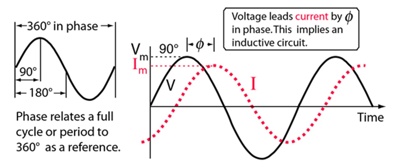
When capacitators or inductors are involved in an AC circuit, the current and voltage do not peak at the same time. The fraction of a period difference between the peaks expressed in degrees is said to be the phase difference. It is customary to use the angle by which the voltage leads the current when expressing phase difference.
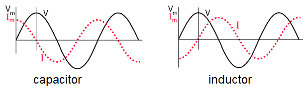
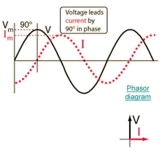
In an inductive circuit, such as a circuit with an inductor (a coil of wire), the current lags behind the voltage. This means that the current reaches its maximum value after the voltage reaches its maximum value. The phase angle between voltage and current in an inductive circuit is positive (+90 degrees) i.e. the voltage leads the current by 90 degrees. In a purely inductive circuit, the current will lag behind the voltage by 90 degrees.
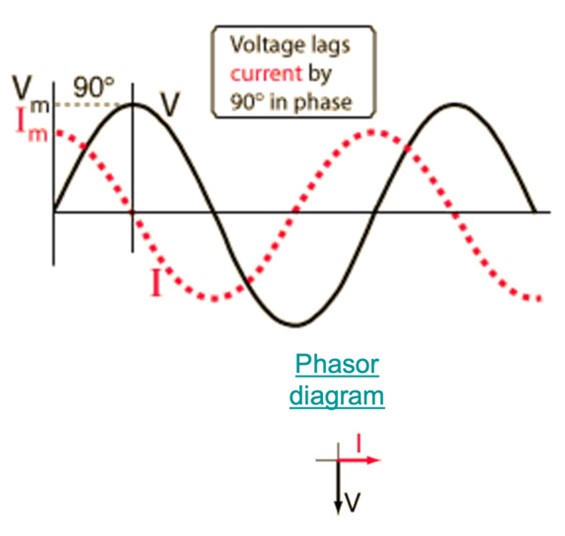
In a capacitive circuit, such as a circuit with a capacitor (a device that stores electrical charge), the current leads the voltage. This means that the current reaches its maximum value before the voltage reaches its maximum value. The phase angle between voltage and current in a capacitive circuit is negative (-90 degrees) i.e., the voltage lags behind the current by 90 degrees.
A useful mnemonic for the phase relationships of current and voltage is ELI the iceman.
Understanding the phase relationship is important because it affects the behaviour and performance of electrical circuits. It helps determine whether the circuit is predominantly resistive, inductive, or capacitive in nature. It also affects things like power efficiency and how energy is transferred in the circuit, and overall circuit efficiency.
Activity
In your own words, explain the following observations about the phase relationship between current and voltage in inductive and capacitive circuits. Email your answers to your tutor.
- In an inductive circuit, such as a circuit with an inductor (a coil of wire), the current lags behind the voltage.
- In a capacitive circuit, such as a circuit with a capacitor (a device that stores electrical charge), the current leads the voltage.
Phasor diagrams
Phasor diagrams are graphical representations used to show the phase relationship between voltages and currents in circuits. They are plotted on a coordinate system and consist of phasors, which are scaled lines representing AC quantities with magnitude and direction. Phasor diagrams are particularly useful for visualising the phase difference between sinusoidal waveforms.
In phasor diagrams, a reference phasor is defined as the one pointing to the right along the x-axis. Other phasors are then defined relative to this reference. Sinusoidal waveforms of the same frequency can have a phase difference, which represents the angular difference between the two waveforms. Terms like "lead" and "lag" or "in-phase" and "out-of-phase" are commonly used to describe the relationship between sinusoidal waveforms.
Vectors are used to represent quantities such as voltage and current in phasor diagrams. They have an arrowhead at one end, indicating the maximum value of the vector quantity, and the end of the vector that rotates. Vectors pivot around a fixed zero point called the "point of origin" and can rotate either clockwise or counterclockwise.
Phasors, on the other hand, represent rotating lines with both magnitude and direction. While vectors have their magnitude as the peak value of the sinusoid, phasors have a complex magnitude as they deal with AC circuits that have reactance. However, the phase angle, direction, and angular velocity remain the same for both vectors and phasors.
| Capacitator AC Response | Inductor AC Response |
 |
 |
Phasor diagrams help overcome the challenge of visualising the angular or phasor difference between sinusoidal waveforms. They provide a graphical representation in the phasor domain, where sinusoids are represented as rotating vectors. This representation helps us understand the phase relationships and compare different sinusoidal quantities at any instant in time.
Phasor diagrams also denote the phase difference between sinusoidal waveforms. The angle between the phasors in the diagram corresponds to the angle of phase difference between the sinusoidal waves. By using a reference phasor, we can determine whether other phasors are leading or lagging in relation to it.
Here are phasor diagrams for these three devices. For a resistor, the current and voltage are in phase because the phasor description of a resistor is VR = IRR. The capacitor voltage lags the current by 90o, and the inductor voltage leads the current by 90o.

Resistor - Voltage in phase with current

Capacitor - Voltage lags current by 90o

Inductor - Voltage leads current by 90o
Although this video contains a lot more information than you need for this course, the explanation of phasor diagrams will help your understanding.
Phasor Diagrams for a Sinusoidal Waveform
As the vector rotates in a counterclockwise direction, its tip at point A completes a full revolution of 360°, which represents one complete cycle. If we transfer the length of its moving tip at different time intervals onto a graph, a sinusoidal waveform will be drawn. The waveform starts at the left side, indicating zero time (t = 0). When the vector is horizontal, the tip represents angles of 0°, 180°, and 360°.
Similarly, when the tip of the vector is vertical, it represents the positive peak value (+Am) at 90° and the negative peak value (-Am) at 270°. The horizontal axis of the waveform corresponds to the angle through which the phasor has moved, measured in degrees. Therefore, a phasor represents a scaled voltage or current value of a rotating vector that is "fixed" at a specific point in time (t). In the example given, the phasor is fixed at an angle of 30°.
Power and Power Factor
Power refers to the rate at which energy is transferred or consumed in an electrical circuit, i.e., how quickly work is done or how much energy is used per unit of time.
Power factor is a measure of how effectively electrical power is being used in a circuit. It indicates the relationship between the real power (useful power) and apparent power (total power) in an AC circuit. Power factor is expressed as a value between 0 and 1, or as a percentage between 0% and 100%.
A high-power factor means that the circuit is utilizing electrical power efficiently, while a low power factor indicates a less efficient use of power. A power factor of 1 (or 100%) indicates that all the power supplied by the source is being used effectively.
Let's consider the effects of the phase relationship between voltage and current on power and power factor. In an AC circuit, the voltage and current waveforms are not always perfectly aligned or in sync. The phase relationship between voltage and current can be categorised into three cases: in-phase, leading, and lagging.
- In-phase: When the voltage and current waveforms reach their peak values and zero points at the same time, they are said to be in-phase. In this case, the power factor is at its maximum value of 1, indicating efficient utilization of power.
- Leading: When the voltage waveform leads the current waveform, it means the peak of the voltage waveform occurs before the peak of the current waveform. This results in a leading power factor, which is typically seen in capacitive circuits. A leading power factor means that the circuit is returning some of the energy back to the source, leading to a less efficient use of power. The power factor in this case is less than 1.
- Lagging: When the current waveform lags behind the voltage waveform, it means the peak of the current waveform occurs after the peak of the voltage waveform. This results in a lagging power factor, which is commonly seen in inductive circuits. A lagging power factor means that the circuit requires additional energy to overcome the inductive effects, resulting in less efficient power utilization. The power factor in this case is less than 1.
It is therefore important to manage the phase relationship and strive for a high-power factor to ensure efficient energy consumption in electrical systems.
A lagging power factor affects the efficiency of power transmission and utilization and requires additional electrical resources to compensate for it. Power factor correction techniques, such as adding capacitors to the circuit, can be employed to improve the power factor and minimise energy losses.
Activity
Create a table summarising Phase Relationships between Voltage and Current in Inductive and Capacitive Circuits using the categories provided. Download this worksheet.