Introduction
In this topic we’ll:
- explain key terms related to technical drawing and landscape design and construction
- demonstrate how to calculate the size of objects at a range of different scales and explain common scales used in landscape design and construction
- walk through the steps involved in drawing up a base plan for a garden.
By the end of this topic you’ll be able to:
- Use technical drawing terms correctly.
- Calculate dimensions for drawings based on the real-world dimension and the drawing scale
- Draw a base plan for a garden, including accepted graphic symbols, annotations, and a basic title block.
We strongly recommend you work through this whole topic before you set about drawing up the base plan for your assessment.
Let’s quickly look at some of the terms we’ll be using. In technical drawing, and landscape design and construction:
- Plan means a top-down, orthographic drawing.
- Orthographic means a drawing of three-dimensional objects as if they are flat (two-dimensional) and all parallel lines are drawn parallel. This is different from a perspective drawing.
- Perspective drawing means a drawing where all parallel lines are drawn so they converge at a single point, known as a vanishing point.
- Elevation means a side-on orthographic drawing.
- Section means a side-on, orthographic drawing that cuts through an object, usually used to show how the object is constructed.
- A Base Plan is a plan drawing that contains all of the site buildings and features in their correct locations and to the correct size for the scale being used.
- A Site Analysis Plan is an overlay (layer) drawn on top of a base plan which shows the locations of environmental information that will help guide the garden design.
- Portrait page layout means a page that is taller than it is wide.
- Landscape page layout means a page that is wider than it is tall.
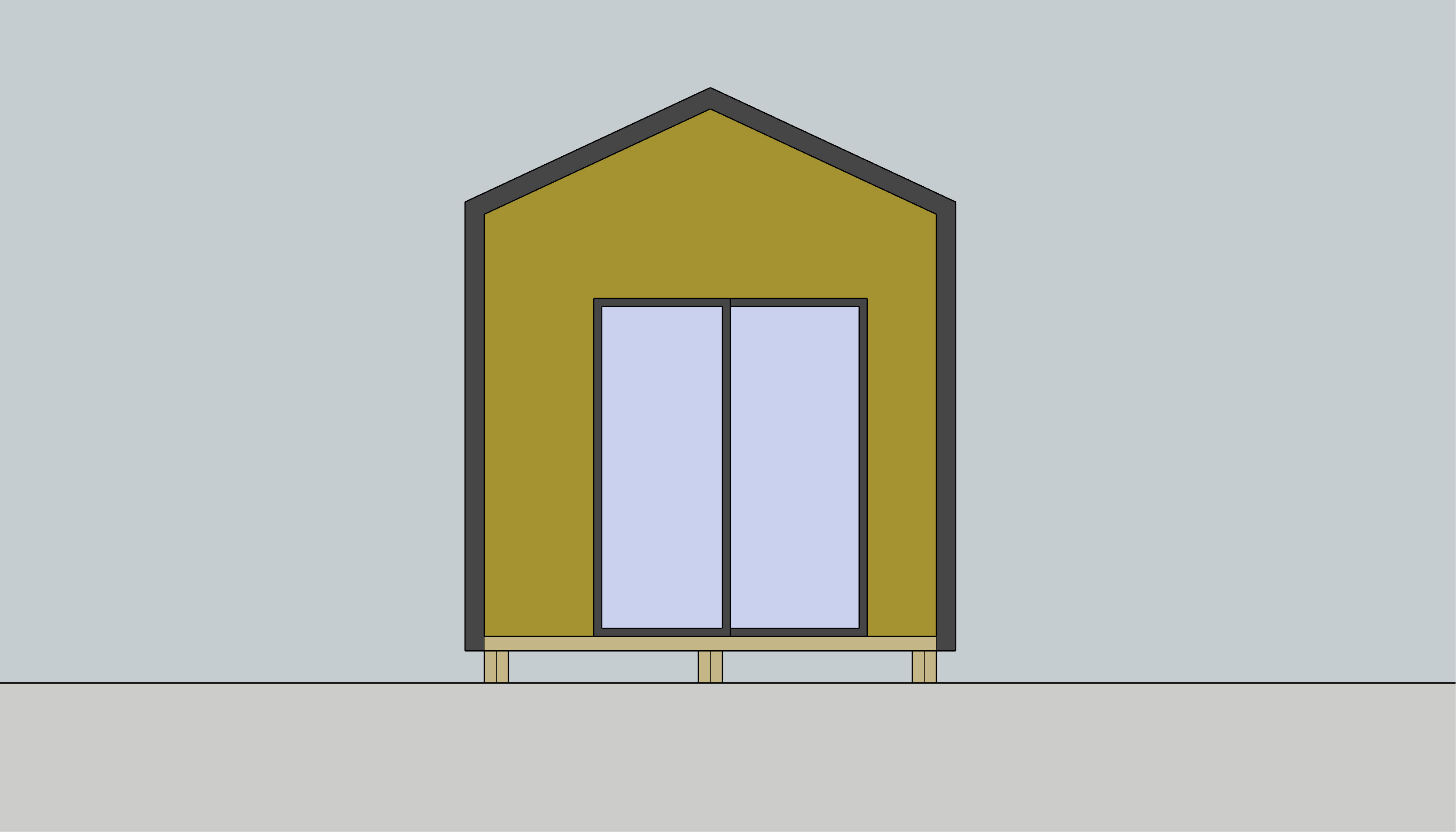 This elevation drawing uses an orthographic projection.
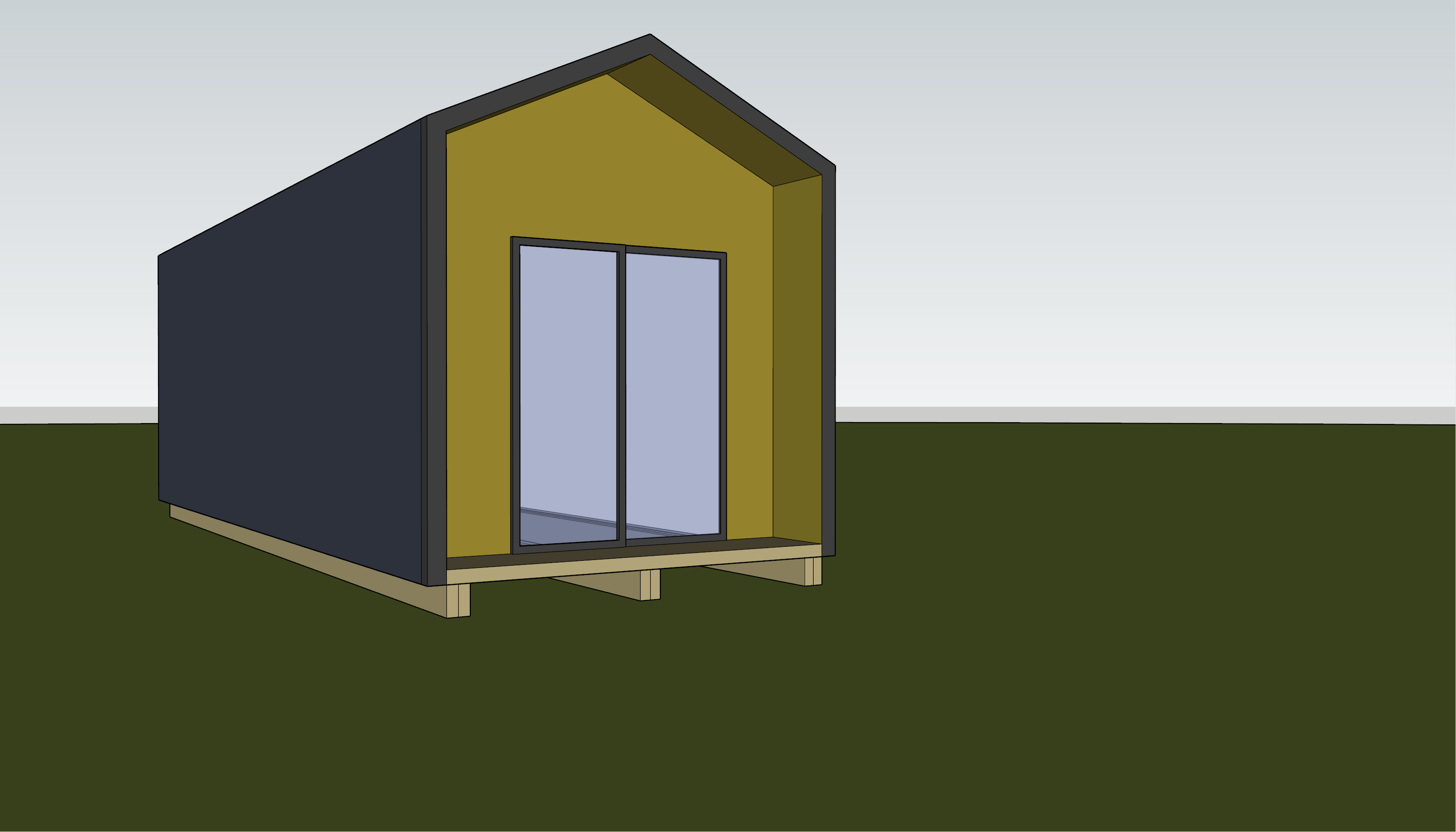 This image shows the same building but as a perspective drawing.
It is a good practice to learn to draw landscape plans at a scale of 1:100. A scale of 1:100 means that a distance of 100 units on the ground will be drawn as one unit on the page. For example, a building wall that is 12 metres long, will be drawn on the page as a line that is 12 centimetres long (12m is 1200cm so 1200 divided by 100 (the scale) equals 12cm).
This is made a little more complicated because we should be working with millimetres, so really we should think of this wall as being 12000mm in the real world which is 120mm when drawn at a scale of 1:100.
Let’s quickly look at some examples of objects drawn at different common scales:
| Object | Real world dimension | Scale | Calculation | Scaled dimension |
|---|---|---|---|---|
| Building wall | 12000mm (12m) | 1:100 | 12000/100 | 120mm (12cm) |
| Fence | 88000mm | 1:100 | 88000/100 | 880mm |
| Driveway | 2400x6000mm | 1:50 | 2400 / 50 and 6000 / 50 | 48x120mm |
| Water tank | Diameter: 3200 | 1:20 | 3200 / 20 | Diameter: 160mm |
We use a 1:100 scale for plan drawings wherever possible. This way, as you do more drawings at this scale, you’ll start to get a sense for how big to sketch objects, instinctively. Additionally, you’re less likely to make mistakes when transferring real world measurements to the page because it’s much easier to do the conversions in your head by simply dropping off the last two digits. For instance 13240mm becomes 132mm (don’t worry about the missing 40mm – the drawing is not precise enough that it will make a difference).
Other scales may be used for different purposes, for example:
- 1:200, 1:500, 1:1000 scales are often used for regional (neighbourhood) plans
- 1:50 and 1:20 are commonly used for section and elevation details or construction drawings.
Activity

The first task when drawing up a base plan is to choose the right size paper.
We know Genevieve’s site, which we will refer to as the Martin Garden, is roughly 26m x 20m. At a scale of 1:100, this is 260mm x 200mm. Technically this does fit on A4, but it would leave us only 37mm in one direction and 10mm in the other for space around the drawing. That’s not going to be big enough space for a title block or any annotations, so we’ll need to use A3.
Next we’ll draw the base plan onto a piece of paper in the middle of the page.
Start by setting up the page on your drawing board, making sure it is level, and secure it in place with the built in clips or with masking tape or removable tape.
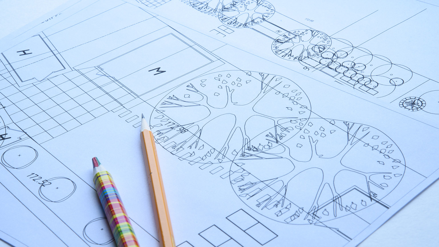
Adding construction lines
As we learned earlier, it is easiest to draw light lines with an H pencil such as a 2H. When we’re drawing out our plan, we start by drawing in very light pencil lines called construction lines. It is fine for construction lines to run almost the whole width of the page.
Hold the ruler firmly in the correct place and then drag your sharp 2H pencil along the paper pressing it slightly against the ruler to form a straight line. If you need another parallel construction line, use a ruler to measure the distance perpendicular to your first line and place a faint mark there with your pencil. Now move your ruler up to the mark and then draw that construction line.
- Draw the outline of the main building – this should be aligned so it sits level on the page. When you are joining up two parallel lines with a perpendicular line, you don’t need to draw that line all the way to the edge of the page. Just make it long enough to join and slightly overlap the two parallel lines.
- Add depth to the walls by drawing a set of lines 2mm away from the main wall lines on the inside of the building.
- Mark the locations of windows and doors. We’ll show you how to draw these later, but for now just use short lines perpendicular to join the inner and outer wall lines.
Locating other features
Next mark the location of the boundaries using your trilateration measurements. For each point you have trilateration measurements for:
-
Extend your drawing compass to the scaled measurement. For instance, if the distance between point A (known) and point C (unknown) is 3600mm, and you’re working at a scale of 1:100:
- press the needle gently into one of your plastic rulers at the 0mm point then
- extend the pencil end so it touches 36mm (3600 / 100)
- Press then needle into point A on your drawing.
- Use the compass to scribe an arc where you expect point C to be. It’s a good idea to draw a reasonably long section of the arc for the first measurement.
- Repeat steps 5-7 for the measurement you have for B (known) to C.
- Where the two arcs cross, is the location of point C.
- Use your eraser to rub out as much of the arcs as you can without rubbing out point C. This will help keep your page uncluttered.
- Repeat this process for all trilateration measurements, generally working in this order:
- site boundaries
- other buildings
- surfaces, e.g. driveways and paths
- main trees and shrubs. As you do each one draw a circle around it that represents the spread of the tree. For instance, if the tree’s spread is 5000mm, use the 50mm circle template for a 1:100 scale drawing.
- Remember not to draw those features identified in your site appraisal as being removed.
Example
From point A, draw an arc which is the scaled length of the distance between points A (known) and C (unknown).

Repeat the process for the distance from point B (known) to point C. Where the points cross is the location of point C. The arc in this image is deliberately drawn longer than necessary to show that it is an arc rather than a straight line.

Adding buildings that are at an angle
In some situations the buildings on site will be at different angles to one another. Where this is the case:
- Trilaterate the two endpoints of one wall.
- Draw a line that joins these two points.
- Unsecure (untape) your drawing and rotate the page so that the line you’ve just drawn lines up with either your horizontal or vertical ruler.
- Re-secure the page and carry on drawing up the building.
- Return the page to the starting orientation when you’ve finished drawing the other buildings.
Checking your drawing
Before you call the pencil done, go back to your rough measurements and make sure you’ve added everything you meant to.
Missing and conflicting information
Occasionally, when you start drawing up your plan you’ll find that you’ve forgotten a measurement or two. Equally, sometimes the measurements you do have may seem incorrect. For example you might draw a feature and when you’re plotting the next points you find that they cross over the last feature.
In the first instance, refer to your photos. They may jog your memory, or you might be able to use the size of a known object to estimate the size of an unknown object that is in the same photos. If the measurements are really important, you might need to go back and measure them again. Talk to your client before you do to make sure they’re happy for you to come around.
When drawing a landscape plan there are a few symbols that are commonly used. To make your drawings easy to understand by others it's a good idea to use these conventions too. The main ones are shown in the drawing below.
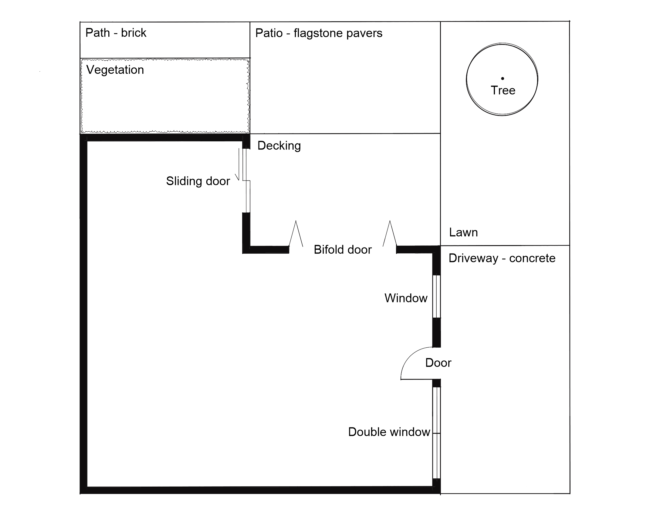
Each is described in more detail, below.
| Object | Description |
|---|---|
| Building wall | Commonly drawn 2mm wide at 1:100 scale. |
| Window | The line running the length of the window represents the glass window pane. Where the window has multiple ‘bays,’ divide it up into the relevant number, as shown with the double window in the drawing. |
| Door | The direction of the arc shows which way the door opens (inwards or outwards, left hinge or right hinge). Use a circle template or drawing compass to draw the arc. |
| Sliding door | The arrow indicates which panel slides and in which direction it slides open. |
| Bifold door | Make sure the drawing shows the correct direction of opening (which is almost always outwards). |
| Fence | Fences are usually shown as a thick line up to 1mm thick. |
| Existing trees | There are many different styles of trees. The one shown here is a really simple (and quick!) one to get you started. Use two different pens, e.g. a 0.2mm and a 0.8mm to do the overlapping circles. The dot in the middle shows that this is an existing tree. A cross is used to show proposed trees (you’ll use this later in the programme). |
| Garden areas | A row of joined up lowercase letter “m” is the simplest graphic for planting masses; a good one to get started with. |
For the base plan it is best to use labels like “Decking,” “Brick,” “Lawn” to indicate the main surfaces. These are easier to read through layers of tracing paper than using graphic symbols.
Now that the site is fully detailed in pencil, we need to go over it using our ink pens. We do this so that the drawing is easy to see through several layers of tracing paper and photocopies well.
Activity
Complete the activity below to refresh your memory of how to get the best out of your ink pens.
When to use each pen
As a general rule, use heavy lines for things that are important or are close to the viewer. For instance, the following features are listed in approximate order of importance, from most important, to least important:
- buildings
- boundaries
- trees
- fences
- other vegetation
- surface outlines
- annotations
- surface graphics
- leader lines.
When we’re drawing a plan, we’re representing the garden as if we’re looking down at it from above. In this sense, the things that the viewer can see (from closest to furthest away) are:
- trees
- buildings
- fences
- shrubs
- decks
- low ground cover plants
- lawn
- hard surfaces at ground level.
You might like to use the following table as a rough guide. If you don’t have the exact same pens, use the nearest size, giving mind to the points mentioned above.
| Pen size (mm) | Examples of use |
|---|---|
| 0.8 |
|
| 0.5 |
|
| 0.3 |
|
| 0.2 |
|
| 0.1 |
|
| 0.05 |
|
Avoiding smudging
Remember to give the ink time to dry before putting a ruler, circle template or your hand on it.
If you find that the base of your hand smudges the ink even after it’s had time to dry, you can take a small piece of blank paper and rest your hand on that as you do your linework. When you slide your hand the paper will slide with it.
Practice
Practice using your drawing board, rulers, and pencils to draw up your own version of the house and garden shown in the topic on landscape graphics, above, at 1:100 scale on a sheet of blank paper. The site is about 14m x 14m. It’s ok to estimate or make up the measurements to suit.
Don’t include any labels, just add your name and the date somewhere. Once you are finished with your drawing, head to the Drawing Practice forum thread to upload your photo. Don’t forget to check out the work that your classmates have done, give them a “like” if you are impressed by their work.
At this point we’ve got the key information on the page, but chances are the main drawing is not in the best place.
It’s important to position the drawing correctly to make it easy for people to interpret it and give enough space for notes that you’ll add to future drawings.
You’ll be tracing over this base plan to create new drawings so it's worth taking the time to set it up correctly now.
Very lightly, draw a rectangle around the site as small as possible but that still fits the whole site. This is known as a bounding box – the smallest rectangle that encloses a drawing. Measure the height and width of the bounding box.
Now you need to work out how to orient your drawing (landscape or portrait page layout). There are four things to consider:
- where possible, the title block should be at the right bottom corner
- where possible, orient your drawing so north is up
- where possible, orient your drawing so it is in landscape page layout
- there should be a border of at least 10mm of blank space around the edge of the page.
If you can’t do all of these things, your best option is to choose the orientation that gives:
- space for the title block at the bottom right corner
- the most blank space to the sides of the drawing rather than the top and bottom. This is because it’s best to put your annotations (notes) off to the side.
Positions of the key elements
The two elements you need to plan for are the drawing and the title block.
You know the space needed for the drawing; the bounding box you measured earlier.
If you plan on using our standard title block, it's appropriately 130mm wide and 30mm tall.
With these two pieces of information we can now set out our page. The simplest way to do this is cut out two pieces of paper that are these sizes – one for the drawing and one for the title block. The title block can be either a blank piece of paper, or you can go ahead and print out the title block from the last section of this topic.
For the drawing use a blank piece of paper and draw an arrow to represent north, or if you have a scanner and printer, cut out the drawing itself.
Place the title block in the bottom right corner, 10mm in from the bottom and right edges of the main sheet of paper. Then place the main drawing cut-out onto the page where it fits best. If there isn’t enough space, try turning the page around and laying out the elements again.
The following image show two ways of laying out a page. Both are acceptable.

When you find the best orientation and locations mark these and then either:
- put another sheet of tracing paper on top of your drawing, offset to best position the drawing on the new page, then trace the drawing onto that page, or
- cut the drawing out and tape it in the correct position onto the new page using invisible tape, add the title block and then photocopy the page.
Annotations are written notes on your drawing. They should be written in capital letters, as small as is legible, with a 0.1mm pen. Place a sheet of graph paper behind the tracing paper of your drawing and make sure the lines are parallel to the lines in your drawing, then write.
With a bit of practice you should be able to write annotations at 2mm (one grid line on graph paper), but if that’s a struggle, start out at 4mm (two grid lines on graph paper). You’ll probably be surprised with how easy it is to read writing at this size and will find it quick to write.
Provided you know how to spell the words you want to write on your plan you should be able to write annotations straight on with pen – no need to write it in pencil first.
On a base plan, you shouldn’t need many annotations, but when it comes time to draw up your new garden design, you’ll probably need a lot.
For now, you only need to label the buildings and surfaces, such as:
- House
- Garage
- Garden shed
- Deck
- Path - brick
- Driveway - coarse gravel.
Practice
Practice writing annotations on tracing paper using graph paper beneath to provide you the lines to write on.
Try writing a whole sentence of text at 4mm (two grid squares) high and then the same sentence at 2mm (one grid square high).
Are they both easy to read? Which did you find easier to write?
Leader lines
Leader lines are the lines that point to objects on the drawing and link to annotations. These should be completely horizontal.
Work out the best place to put text for a feature on the drawing. This should be in the blank space to the left or right of the feature. Use graph paper under the drawing to help line it up. Write the text using a 0.1mm pen and then use your horizontal ruler and a 0.05mm pen to draw a leader line joining the annotation and the feature on the drawing.
A title block is a collection of basic information about the drawing. Title blocks are essential on drawings that are provided to the client or contractors, but it’s a good practice to keep this information on all of your drawings.
At a minimum you should include:
- the name of the drawing
- the site address
- your name
- the date drawn
- the scale
- orientation (direction of north).
In the future, for client-facing drawings you’ll also include the project name, your business name and logo, and your contact details.
The two most common ways to add a title block are:
- Print the title block, cut it out, and stick it onto your drawing with invisible tape.
- Draw the borders and north arrow in with pencil and then using ink pens. Place graph paper behind the tracing paper your drawing is on and write in the information using a fine ink pen. If writing the title block by hand, use all capital letters as you have done for your annotations.
Here is a Word document that contains a basic title block that you might like to use: Simple Title Block.
And that’s it! Ka pai temahi!
Now you’re ready to draw up your base plan for Assessment LDB02A2.
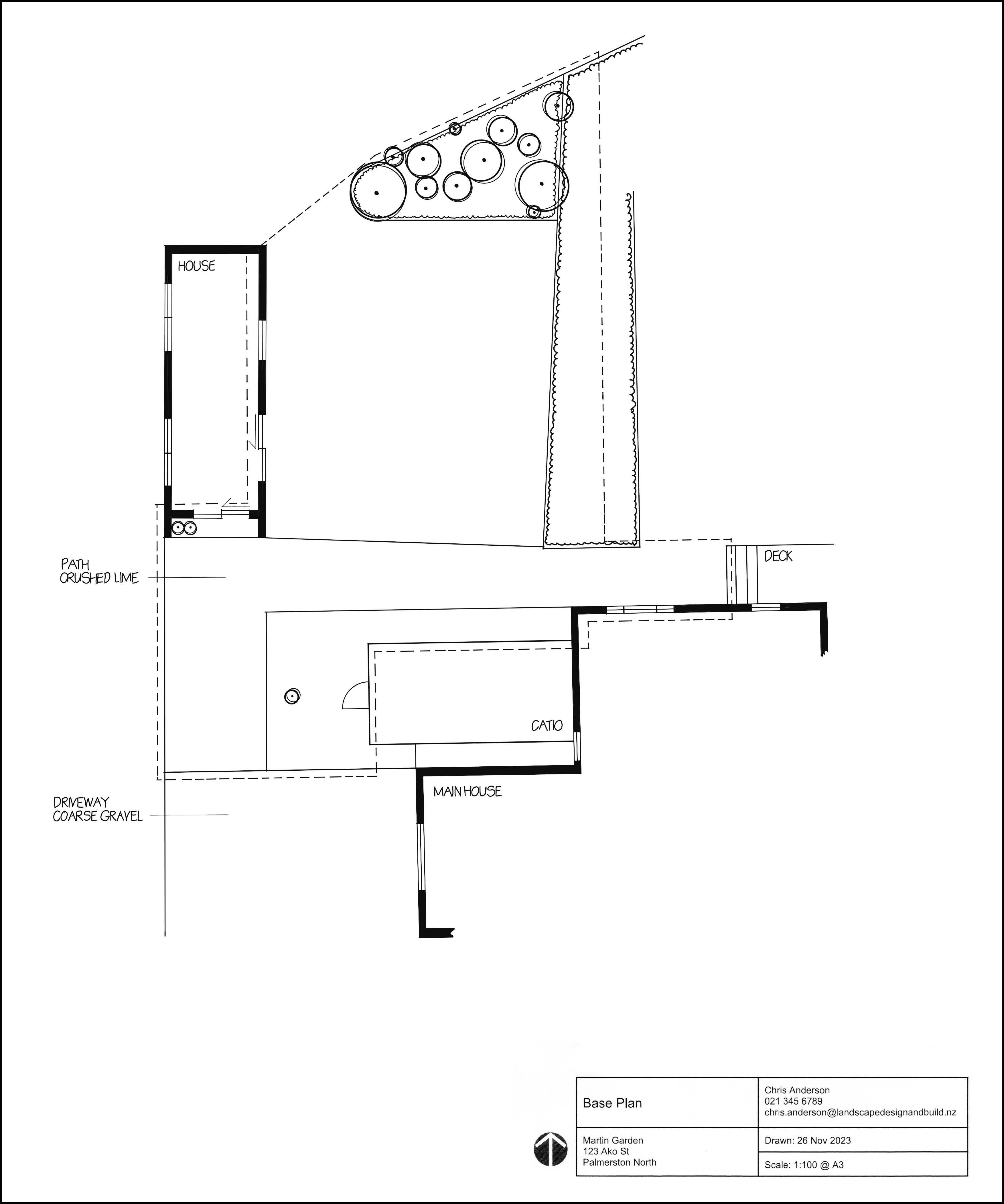
Base Plan for Genevieve’s site – the Martin Garden – set out on an A3 page. Because there are no legal site boundaries related to this project, we’ve used a dashed line to show the part of the site that is being redesigned:
Summary
In this topic we’ve:
- introduced key technical drawing terms
- learned to calculate the size of objects at a range of different scales
- explained common scales used in landscape design and construction
- worked through the steps involved in drawing up a base plan for a garden.
Now we’re ready to move onto the final topic for this module.