Week 2
| Day One | Day Two | Day Three | Day Four | |
|---|---|---|---|---|
| Course Content | Types of RCDs - Type AC, Type A, and Type B | Surge protection devices, isolators and regulators. | Design an appropriate circuit protection plan for a typical residential electrical system in NZ. | Rewiring and Replacing Rewireable fuses. |
| Self-directed Learning | Activity comparing three types of RCD | Make a video - 'Isolators in My Home.' | Continue working on Circuit Protection Design task. | Video explaining steps to replace a fuse carrier with a plug-in circuit breaker. |
In order for you to gain the most value from your qualification and to prepare you for your assessment and the industry, make sure you complete all of the online and SDL tasks.

What we're covering:
- Type AC; A; and B RCDs.
According to Clause 2.6 of the New Zealand Wiring Rules there are three types of Residual Current Devices commonly used in New Zealand. These are:
- Type AC RCD.
- Type A RCD.
- Type B RCD.
Exercise 6
This exercise requires you to investigate the three types of RCDs.
- Begin by finding out what each of these RCD terms mean:
- Tripping characteristics.
- Sensitivity rating.
- Protection capabilities.
- Trip speed.
- Trip time.
- Rated current.
- Discrimination.
- Applications.
- Research the different types of RCDs - Type AC, Type A, and Type B, based on each of the terms in step 1 (Values will vary depending on the specific RCD model and installation conditions chosen. Make a note of your references used so that you can justify your answers.).
- Use the information to create a comparison table of the three types of RCD.
- Answer the questions below about the RCDs.
- Email your comparison table and your answers to the questions to your tutor, in preparation for a class discussion.
Questions
- Why is it important to use RCDs in electrical installations?
- Which type of RCD is the most sensitive and why?
- What is the purpose of discrimination in RCDs?
- What are the main differences between Type AC, Type A, and Type B RCDs?
- What are the key technical specifications that you should consider when choosing an RCD?
- In what types of electrical installations would you use a Type B RCD, and why?
- Which type of RCD would you recommend for a residential installation, and why?
- What are some common causes of unwanted tripping in RCDs, and how can you prevent them?
- What are some best practices for maintaining and testing RCDs in electrical installations?
- Why is it important to choose the right type of RCD for a particular application?
Self-directed Learning
Complete the activity above comparing the three types of RCD.

What we're covering:
- How surge protection devices are used
- Additional circuit protection
A surge protector is a device that protects electronic equipment from power surges caused by lightning strikes, power outages, or other sudden increases in electrical current. It combines both surge arresters and suppressors to provide comprehensive protection against momentary overvoltage.
Read about how a surge protector works on this page.
Construction: Surge protectors typically consist of three main components: the metal oxide varistor (MOV), the thermal fuse, and the surge protection indicator. The MOV is a device that conducts current when a voltage spike occurs, diverting the excess current away from the connected equipment. The thermal fuse is a safety feature that will cut off the current if the MOV gets too hot, preventing it from overheating and causing a fire. The surge protection indicator is a light or alarm that signals whether the surge protector is functioning properly.

Operating Principles: Surge protectors work by diverting excess electrical current to ground when a voltage spike occurs. When the voltage of the electrical system exceeds the level that the equipment can handle, the MOV conducts current and directs the excess energy to ground. The thermal fuse is designed to detect when the MOV is getting too hot and will disconnect the circuit if necessary to prevent the MOV from overheating.
Typical Ratings: The typical ratings for surge protectors in New Zealand include the voltage rating, which is usually 240 volts, and the energy absorption rating, which ranges from 200 to 1000 joules. The surge current rating is another important factor, which indicates the maximum amount of current that the surge protector can handle during a voltage spike.
Applications: Surge protectors are commonly used to protect electronic equipment in homes, offices, and other environments where electrical surges can occur. They are commonly used to protect computers, televisions, home theatre systems, and other sensitive electronic equipment. Surge protectors are also used to protect industrial equipment, such as motors, generators, and other heavy machinery.
Watch this video which looks inside a 13,500A surge protector.
Inside a 13 500A surge detector.
Exercise 7
Additional Circuit Protection
Isolators
Isolators, also known as isolation switches or disconnect switches, are electrical devices that provide a means of disconnecting an electrical circuit or appliance from the power supply. This is done using a switch or other similar mechanism that breaks the connection between the circuit or appliance and the power supply. Isolators are commonly used in electrical installations and systems to provide a safe and convenient means of disconnecting power for maintenance, repair, or safety purposes.
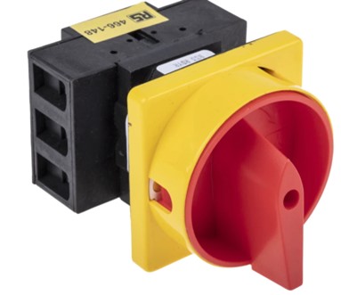
Construction: An isolator typically consists of a switch mechanism, an insulating enclosure, and terminals for connecting the circuit or equipment. The switch mechanism may be manual, operated by a handle or knob, or motorised, operated by a motor or solenoid. The insulating enclosure is usually made of non-conductive material, such as plastic or ceramic, and is designed to prevent accidental contact with live parts. The terminals are usually designed to accept cables or busbars and may be rated for different current and voltage levels.
Operating principles: Isolators work by providing a means of opening or closing a circuit, and physically isolating the circuit or equipment from the power source. When the isolator switch is in the closed position, the circuit is connected to the power source and can operate normally. When the isolator switch is in the open position, the circuit is disconnected from the power source and is isolated for maintenance or safety purposes.
Typical ratings: Isolators are available in a range of ratings, depending on their intended application. Some typical ratings include:
- Voltage: from low voltage (e.g., 12V) to high voltage (e.g., 1000V or more)
- Current: from a few amps to several thousand amps.
- Frequency: typically rated for 50Hz or 60Hz but may be rated for higher frequencies in some applications.
- Short-circuit current rating: the maximum current that the isolator can safely interrupt without damage.
Applications: Isolators are commonly used in a variety of applications, including:
- Electrical installations: to provide a safe means of disconnecting power for maintenance or repair.
- Industrial equipment: to isolate machines or equipment for maintenance or safety purposes.
- Power distribution: to isolate sections of a power grid or distribution network for maintenance or repair.
- Renewable energy systems: to isolate solar panels or wind turbines for maintenance or repair.
- Safety systems: to provide an emergency means of shutting down power in case of an emergency or fault.
Voltage regulators
Although not specifically designed as circuit protection devices, voltage regulators can help to protect electronic devices from overvoltage and undervoltage conditions by regulating the voltage output of a power supply to provide a stable and consistent voltage level, regardless of changes in input voltage or load current.
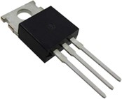
Construction: Voltage regulators typically consist of a voltage reference, an error amplifier, a series pass element, and feedback and control circuits. The voltage reference sets the desired output voltage, and the error amplifier compares the actual output voltage to the reference voltage and generates an error signal. The series pass element adjusts the output voltage to correct for the error, and the feedback and control circuits stabilise the voltage output.
Operating principles: Voltage regulators work by regulating the output voltage of a power supply or battery to a specified level, regardless of changes in input voltage or load current. The regulator maintains a constant output voltage by comparing the actual output voltage to a reference voltage and adjusting the series pass element to correct for any errors.
Typical ratings: Voltage regulators are available in a range of ratings, depending on their intended application.
Applications: Voltage regulators are commonly used in a variety of applications, including:
- Electronic equipment: to regulate the voltage of power supplies for computers, televisions, and other consumer electronics.
- Power grids: to regulate the voltage of power transmission and distribution systems.
- Renewable energy systems: to regulate the voltage of solar panels and wind turbines.
- Automotive and aerospace systems: to regulate the voltage of batteries and electrical systems in vehicles and aircraft.
- Industrial and manufacturing equipment: to regulate the voltage of power supplies for machinery and equipment.
Self-directed Learning
- Create a short video entitled "Isolators in My Home”.
- Identify five isolators in your home or workplace.
- For each isolator, take a video and explain the purpose and importance of the isolator in your own words. (You can be creative with your explanations and use props or visual aids to help illustrate your points if you wish to.)
- Share your video on the class forum.
- As a class, discuss the different isolators found in your homes, the importance of isolators in protecting electrical installations, and any safety considerations related to isolator use.

What we're covering:
- designing a circuit protection plan
The objective of this exercise is to design an appropriate circuit protection plan for a typical residential electrical system in New Zealand.
Exercise 8
Instructions:
- Select the appropriate circuit protection devices to be installed based on the information provided.
- Research and apply relevant New Zealand standards, such as the Electrical Code of Practice and the Wiring Rules.
- Present your findings in a table as shown.
Specifications:
- Service voltage: 230VAC
- Service current: 100A
- Number of circuits: 20
- 10 lighting circuits (10A)
- 3 appliance circuits (16A)
- 3 socket-outlet circuits (20A)
- 2 HVAC circuits(16A)
- 2 hot water cylinder circuits (20A)
- Expected loads: lighting, appliances, electronics, heating, and cooling.
- Lighting: 2,500W
- Appliances: 4,800W
- Socket-outlets: 4,800W
- HVAC: 6,400W
- Hot water cylinder: 4,800W
Example Table
| Device | Placement | Type of Circuit | Rating | Purpose | Cost |
|---|---|---|---|---|---|
You can download a copy of the table template here.
Self-directed Learning
Continue working on the Circuit Protection Design task. Email your final plan to your tutor.

What we're covering:
- switchboards
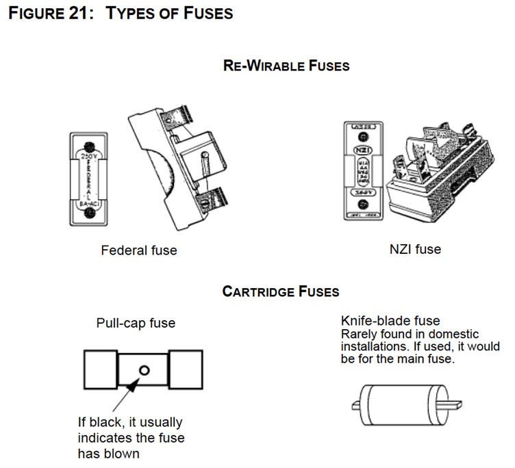
- types of fuses used in New Zealand
- changing a fuse
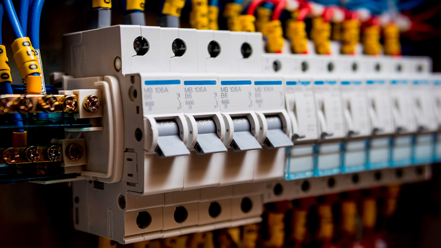
The switchboard in a home protects the electrical wiring system. It is comprised of a main power switch and several fuses or circuit breakers, each corresponding to a different area of wiring in the house. If an electrical fault occurs, the corresponding fuse will blow, or the circuit breaker will trip to prevent overloading or fire hazards.
Semi-enclosed rewireable fuses (SERFs) were once a common type of fuse used in electrical installations in New Zealand. However, as of 2018, they are no longer permitted for new electrical installations or for replacement of existing SERFs in certain situations due to safety concerns and the availability of newer and safer types of fuses.
Watch the following videos which demonstrate how to change a fuse, should the situation arise with an old switchboard.
Exercise 9
Exercise 10
As an electrical apprentice, you are asked to inspect an electrical installation that still uses fuses. Write a report on the potential hazards that may arise from using fuses instead of mini circuit breakers and the benefits of upgrading to mini circuit breakers. Your report should include information about:
- Potential hazards associated with using fuses instead of mini circuit breakers
- Benefits of upgrading to mini circuit breakers
Post your report on the forum when you are complete. Make sure you read and comment on some of your classmate's reports.
Replacing rewireable fuses with plug-in circuit-breakers
Rather than replacing fuses, you are likely to be called upon to replace rewireable fuses with circuit-breakers. Refer to Appendix A5 in the New Zealand Electrical Code of Practice for Homeowner/Occupier’s Electrical Wiring Work in Domestic Installations to answer the following questions.
Exercise 11
- Rewireable fuses can be replaced with plug-in circuit-breakers, as long as the fuse base: (Identify the three reasons)
- Answer the following questions about the correct fuse/circuit-breaker match.
- What is the recommended circuit-breaker amperage for a 5A fuse?
- Which fuse amperage should be paired with a 20A circuit-breaker?
- What circuit-breaker amperage is suitable for a 30A fuse?
- Can a 15A fuse be paired with a 20A circuit-breaker?
- Is it safe to pair a 10A fuse with a 16A circuit-breaker?
- What should you do if you want to have the 30-amp rewireable fuse for an electric range replaced with a circuit-breaker?
When you have finished, email your answers to your tutor.
Self-directed Learning
Create a short video in which you explain the steps you would take to replace a fuse carrier with a plug-in circuit breaker. Post your video on the class forum. You may borrow props from your tutor however you MUST NOT do an actual demonstration on a live switchboard.