Week 5
| Day One | Day Two | Day Three | Day Four | |
|---|---|---|---|---|
| Course Content | Loop at the light/loop at the switch wiring. Drawing activity and wiring diagrams. | Types of Switches – Mechanical & Electric. Relays, transistors & diodes. | Lighting circuit - checks and tests. Electric switches cont. – thyristors. Self-check activity. | Design & draw circuits – two-way and three-way circuits. |
| Self-directed Learning | Recap lesson with set of questions and answers. | Types of mechanical switches – operation, applications & images. | Types of mechanical switches – operation, applications & images. | Complete drawings and post on class forum for feedback. |
In order for you to gain the most value from your qualification and to prepare you for your assessment and the industry, make sure you complete all of the online and SDL tasks.

What we're covering:
- loop at the light configuration
- loop at the switch configuration
The method selected for wiring lighting circuits will depend on the wiring system employed. The two most effective configurations when installing lighting circuits are:
Loop at the Light - In loop at the light wiring, the power source is first connected to the light fixture and then to the switch. A twin and earth power feed is run from the switchboard to the first light on the circuit. A twin active wire is run from the light to the controlling switch. The power feed is then looped from the first light to the second light on the circuit, and this process is repeated for all the lights on the circuit. The live and switched live wires are connected in a loop at the light fixture, forming a complete circuit.

Loop at the switch - In loop at the switch wiring, the power source first connects to the switch, and then it goes to the light fixture. The wiring forms a loop at the switch, where the live and switched live wires are connected in a loop. This system is used to avoid using two different types of cable, with the power feed looped at each switch. A twin and earth cable is run from the switch to the light. Careful planning is required to ensure that the number of conductors joined behind the switches does not exceed the recommended limit.

Watch the video discussing the two techniques for wiring – ‘looped at the light’ and ‘looped at the switch’.
How is your house wired Australia
Exercise 25
Loop at the Light Circuit Activity
- Draw a light fixture in the centre of the paper.
- Next, draw a line extending from the light fixture to represent the cable that carries the power.
- Draw the switch on your paper, with two lines extending from the switch to represent the cables that connect it to the light fixture.
- Draw a loop in the cable near the light fixture, with the live and switched live wires connected together in a loop.
- Label the light fixture, switch, and cables on your drawing.
Loop at the Switch Circuit Activity
- Draw a diagram of the loop at the switch wiring method on your paper.
- Draw a light fixture in the centre of the paper.
- Draw the switch on your paper, with two lines extending from the switch to represent the cables that connect it to the light fixture.
- Draw a loop in the cable near the switch, with the live and switched live wires connected together in a loop.
- Draw a line extending from the light fixture to represent the cable that carries the power.
- Label the light fixture, switch, and cables on your drawing.
Finally, draw wiring diagrams for each circuit. Label each component and wire in your diagrams and explain how the wires are connected to each other. Email both diagrams to your tutor.
Self-directed Learning
Answer the following questions from today’s session:
- What is the term for the wiring method used to connect lighting circuits using a twin and earth cable from the light fitting to the switch?
- What determines the maximum number of lights that can be controlled by a one-way loop at the light switch?
- What combination of switches is required to independently control a set of stairway lights from four different locations? Explain your choice.
- Is it possible to use a manufacturer's standard switch for two-way switching? Explain your answer.
- What switching circuit would be the most suitable to control lights on three flights of stairs? Explain your choice.
Email your answers to your tutor.

What we're covering:
- mechanical switches
- Electrical switches
- Relays
- Transistors
- Diodes
Switches are categorised based on their mode of operation. The two main categories of switches are mechanical switches and electrical switches.
Mechanical switches
Mechanical switches are physical devices that use mechanical force to create a connection, or break an existing connection, between two electrical terminals. They typically have a physical lever, button, or knob that is moved to open or close the contacts of the switch. Mechanical switches are often preferred for their simplicity, durability, and low cost. They are commonly used in applications that require a physical switch to be operated, such as light switches or doorbells. Their drawbacks include limited switching speed and susceptibility to wear and tear over time.
Exercise 26
Switches 1 and 2 in the diagram below are SPDT type switches. Complete the following table.
Electric switches
Electric switches are switches that use an electrical signal to control the flow of electricity. They include solid-state switches, such as transistors, diodes, and thyristors, as well as electromechanical switches, such as relays and contactors. Electric switches do not require any physical movement of a lever or button, but instead rely on changes in voltage, current, or magnetic fields to create the connection or break it.
Electric switches are often preferred for their high switching speed, precision, and reliability. They are commonly used in complex electronic circuits, such as computer processors, where fast and accurate switching is essential. Electric switches can be more expensive and complex to use than mechanical switches and may require additional components such as transistors and diodes to function properly.
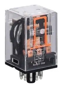
Relays
Relays are electrically operated switches that open and close the circuits by receiving electrical signals from outside sources. For example, when you push the button on a TV remote to watch TV, it sends an electrical signal to the “relay” inside the TV, turning the main power ON.
Relays use an electromagnetic coil to control the position of a set of contacts, which can be either normally open (NO) or normally closed (NC). When the coil is energised, the movable armature or plunger is pulled towards it, causing a set of contacts to either open or close, depending on their initial state. This allows the relay to switch a higher voltage or current than what is required to activate the coil. Relays can be used to switch on or off motors, lights, and other electrical loads.
Watch this video which explains how relays work.
Transistors
A transistor is a semiconductor device that is commonly used in electronic circuits for amplifying or switching electronic signals. It consists of three layers of semiconductor material, two of which are doped with impurities to create regions called the emitter (e) and the collector (c). The third layer, known as the base (b), is sandwiched between the emitter and collector layers.
In its simplest form, a transistor acts as a switch by controlling the flow of current between the emitter and collector terminals. This is done by applying a small current or voltage to the base terminal, which acts as a control signal. When the control signal is applied, it causes a large current to flow between the emitter and collector terminals, effectively turning the transistor "on" or "off".
The two most common types of transistors are PNP and NPN, which refer to the type of semiconductor material used in the emitter and collector layers.
In a PNP transistor, the emitter is made of a negatively charged material and the collector is made of a positively charged material.

In contrast, an NPN transistor has an emitter made of a positively charged material and a collector made of a negatively charged material.

To use a transistor as a switch, the base terminal is typically connected to a control circuit that supplies a voltage or current signal to turn the transistor on or off. In this configuration, the collector and emitter terminals act as the switch contacts, allowing current to flow between them when the transistor is turned on and blocking current when the transistor is turned off.
When a small electric current is sent to the base of the transistor, it acts like a gate that allows a larger current to flow from the collector to the emitter. This is because the current flowing through the base creates a sort of bridge between the collector and emitter, allowing the larger current to flow through the transistor.

By controlling the amount of current sent to the base, we can control how much current flows through the transistor. This makes transistors useful as switches in electronic circuits. When no current is sent to the base, the transistor is turned off and does not allow any current to flow. When a small amount of current is sent to the base, the transistor turns on and allows a larger current to flow through it, acting like a switch.
Transistors are used in a wide range of devices, from radios and televisions to computers and mobile phones.
Read more about how transistors work here.
Watch this video which provides some extra information on transistors and how they work.
Diodes
A diode is an electronic component that allows current to flow in only one direction. It is made of a semiconductor material and has two terminals called the anode and cathode. When a voltage is applied to the anode of a diode that is greater than the voltage at the cathode, the diode conducts electricity and allows current to flow through it. However, when the voltage at the cathode is greater than the voltage at the anode, the diode does not conduct electricity and blocks the flow of current.
This property of a diode makes it useful as a switch. By placing a diode in series with a load, the flow of current can be controlled. When the voltage is applied in the forward direction, the diode conducts, and the load receives power. When the voltage is applied in the reverse direction, the diode does not conduct, and the load does not receive power.

Diodes are also used in rectifier circuits, which convert alternating current (AC) to direct current (DC). In a rectifier circuit, a diode is placed in series with an AC voltage source. The diode conducts when the AC voltage is positive, allowing current to flow in one direction, but blocks current flow when the AC voltage is negative, preventing current from flowing in the opposite direction.
Watch this video which provides some extra information on diodes and how they work.
Self-directed Learning
This SDL is expected to be completed over two sessions (18 and 19).
Briefly describe the operation of each mechanical switch listed in the table in this worksheet. Find an image and an application of each.

What we're covering:
- Thyristors
- Checks and tests
Thyristors
A thyristor is another electronic component that can act like a switch. It is made up of four different parts called the anode, cathode, gate, and the trigger electrode.

When a small signal is sent to the gate, it allows a larger amount of electricity to flow through the thyristor. This is kind of like a "switch" turning on - the thyristor lets electricity flow through when the gate receives a signal.
Once the thyristor is "on", it stays on until the electrical current flowing through it drops below a certain level. This means that it can keep letting electricity flow even if the signal that turned it on has stopped.
Thyristors are useful in electronic devices that need to control the flow of electricity, like dimmer switches or motor controllers. They can handle a lot of electrical current and are very reliable.
Watch this video explaining how thyristors work.
What is a Thyristor? How Thyristors Work?
Exercise 27
Checks and Tests
Once a lighting circuit has been installed, a series of tests must be carried out to ensure that it is functioning correctly and is safe to use. Refer back to previous notes about inspection and testing. These tests include:
- Visual Inspection involves ensuring that the installed circuit and all its components comply with the AS/NZS 3000:2018 clause 8.2.2 checklist and other relevant standards. Wires must be properly routed and supported, the correct size and type of cable must be used, and all connections must be properly made and secured. The visual inspection also ensures that there are no visible signs of damage or wear and that all electrical equipment used in the installation is marked with an appropriate rating. Lamps should be installed to avoid excessive temperature increases, ignition, or degradation of materials.
- Insulation and Continuity Testing is performed using an insulation tester, such as a digital multimeter, to measure the level of insulation present in the circuit, and to indicate whether there is any break in the circuit. Set the insulation tester to the 500V range and test between the conductors. The insulation resistance should be infinity. Refer to AS/NZS 3000:2018 clauses 8.3.5 and 8.3.6 for more detail.
- Earth Fault Loop Impedance testing is carried out to determine the ability of the circuit's protective devices, such as fuses and circuit breakers, to operate quickly enough to prevent a dangerous electric shock. This test involves applying a voltage to the circuit and measuring the resistance of the earth fault loop. The reading obtained is then compared to the maximum values in Table 8.1 of AS/NZS 3000:2018. Refer also to clause 8.3.9. for more information.
Self-directed Learning
Complete the activity about mechanical switches from Session 18.

What we're covering:
- uses and operation.
- key components
In the world of electrical control systems, simple on-off switches are not enough for most processes. They require advanced control systems to manage commands, direct actions, and regulate device behaviour. This is where electromagnetic relays, programmable relays, and programmable logic controllers (PLCs) come in.
Relay logic control (RLC) uses relays as key components. Relays are devices that switch electrical circuits based on external signals. With relay logic, engineers create control systems that handle tasks and ensure proper equipment function.
Electromagnetic relays utilise the principles of electromagnetism to control circuits. They consist of a coil and contacts, where the coil generates a magnetic field that controls the opening and closing of the contacts. Key features of electromagnetic relays include simplicity, reliable switching performance, and widespread application in various control systems.
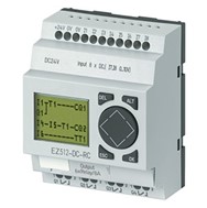
Programmable relays, also known as solid-state relays or smart relays, offer the advantages of electromagnetic relays while incorporating programmable logic capabilities. By integrating microcontrollers and digital circuitry, programmable relays can be programmed to perform specific control tasks. Their key characteristics include programmability, compact size, and additional features such as time delay, counters, timers, and logic functions.
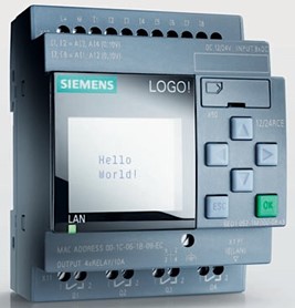
Programmable logic controllers (PLCs) revolutionised automation by combining microcontrollers and solid-state switching. Unlike relay logic, PLCs can be programmed for specific tasks, offering flexibility and customisation. By using software, PLCs handle complex processes, follow instructions, and integrate with other systems.
PLCs represent a highly advanced form of control system technology. They encompass a comprehensive range of features and capabilities for automation and control. Key attributes of PLCs include powerful computing capabilities, extensive input/output options, and the ability to integrate with various systems. PLCs offer unparalleled flexibility, adaptability, and the capacity to handle intricate processes.
While relays, programmable relays, and PLCs handle control and switching, they differ in functionality and capabilities. Electromagnetic relays are reliable and simple, suitable for basic tasks. Programmable relays offer flexibility, programmability, and additional features, but are less powerful than PLCs. PLCs are at the forefront of automation, providing advanced computing capabilities, extensive customization options, and the ability to handle complex control strategies.
Exercise 28
Watch these informative videos about Relay Systems.
What is a Relay System?
What Are the Advantages PLCs Have over Relay Systems?
Operation of Programmable Relays and PLCs
Programmable relays and a programmable logic controllers (PLCs) serve similar functions but differ in terms of complexity and capabilities. Programmable relays are simpler devices with limited functionality compared to PLCs, which offer more advanced capabilities, such as communication modules and integrated programming and HMI features. A table comparing the parts of each system is shown here:
| Parts | Programmable Relay | Programmable Logic Controller |
|---|---|---|
| Power supply | Provides electrical power to the relay | Supplies power to all components of the PLC |
| Input module | Receives signal from external devices | Receives signal from sensors and devices |
| Processor module | Executes control program and makes decisions | Acts as CPU, executing control instructions |
| Memory module | Stores control program and data | Holds program, data and retains information |
| Output module | Transforms control signals into physical actions | Converts control signals to control outputs |
| Communication modules | N/A | Enables connectivity with other devices/systems |
| Programming and HMI | N/A | Software for programming & monitoring the PLC |
PLCs and programmable relays have distinct differences in functionality, programming flexibility, processing power, communication and integration capabilities, as well as scalability and expandability.
PLCs are advanced control systems designed for complex automation tasks. They feature a dedicated CPU, expanded input/output options, and sophisticated programming and HMI features. PLCs excel in handling larger-scale processes and integrating with various systems. They offer extensive programming options, powerful processors, and the ability to communicate with other devices and systems. Moreover, PLCs can be easily expanded to accommodate evolving control requirements.
In contrast, programmable relays are simpler devices suitable for straightforward control applications. They have basic programmability and control capabilities. Programmable relays offer limited functionality, basic programming options, and less processing power compared to PLCs. Their communication capabilities are also more limited, and they may lack extensive integration capabilities. Additionally, programmable relays may have constraints when it comes to scalability and expandability.
Control Programmes for Switching and Controlling Loads
A control programme for switching and controlling loads refers to a software-based solution designed to manage and manipulate various electrical loads in a system. It provides a means to control the operation of loads, such as lights and motors, by sending commands to switches, relays, or other control devices. The control programme acts as an intermediary between the user and the devices, making load control easier and more efficient.
Design of an Entry-Level Control Programme
An entry-level control programme is typically designed with the objective of providing a user-friendly interface that simplifies load switching and control. To achieve this, the programme incorporates several key design elements:
- Graphical User Interface (GUI): The control programme utilizes a graphical user interface that allows users to interact with the system easily. The GUI presents a visual representation of the loads, providing intuitive controls such as buttons, sliders, or checkboxes. This visual interface makes it simpler for users, even those with limited technical knowledge, to understand and operate the programme effectively.
- Load Configuration: The control programme provides a mechanism for users to configure and define the loads they want to control. This includes specifying the type of load (e.g., lights, motors, heaters) and assigning unique identifiers or names to each load. Additionally, users may be able to set parameters such as voltage levels, current limits, or scheduling options for individual loads.
- Communication Interface: To enable interaction with physical devices, the control programme incorporates a communication interface. This interface allows the program to communicate with external devices like relays, switches, or sensors, which are responsible for the actual switching and control of the loads. The interface may utilize protocols such as Modbus, Ethernet, or wireless technologies to establish communication between the programme and the devices.
Function of an Entry-Level Control Programme
The primary function of an entry-level control programme is to provide a simplified yet effective means of switching and controlling loads. The programme performs several essential functions to achieve this goal:
- Load Monitoring and Status Display: The control programme continuously monitors the status of the connected loads, providing real-time feedback on their operational state. It displays this information on the GUI, allowing users to quickly identify which loads are powered on or off. This feature enhances safety and facilitates troubleshooting by enabling users to identify potential issues at a glance.
- Load Switching and Control: The control programme enables users to switch loads on or off conveniently through the GUI. By interacting with the graphical controls, users can send commands to the connected devices, activating or deactivating the respective loads. This functionality allows for efficient and centralized control of multiple loads from a single interface, reducing the need for manual intervention.
- Load Scheduling and Automation: An entry-level control programme often includes scheduling and automation capabilities. Users can define specific time-based or event-based scenarios for load control. For instance, they can schedule lights to turn on or off at specific times or trigger load control based on environmental factors or sensor inputs. This automation enhances energy efficiency, convenience, and overall system management.
- Alarms and Notifications: To ensure effective load management, the control programme can generate alarms or notifications for critical events or abnormal conditions. For example, it can alert users when a load exceeds a specified current limit, indicating a potential fault. These notifications help in prompt troubleshooting and maintenance, preventing potential damage.
Self-directed Learning
Consider the following questions. Post your ideas on the class forum for discussion.
- What are the key characteristics of entry-level control programmes for programmable relays?
- How do entry-level control programmes for programmable relays function?
- What is the purpose of entry-level control programmes for PLCs?
- Describe the design approach of entry-level control programmes for PLCs.
- How do entry-level control programmes for PLCs differ from those for programmable relays?