What we're covering:
- devices that protect electrical circuits
For every electrical installation, it is necessary to ensure the safety of personnel as well as the protection of equipment from electrical faults. All electrical wiring systems and all electrical apparatus associated with wiring must be protected to:
- Prevent damage by fire or shock.
- Maintain continuity of the supply.
- Disconnect faulty apparatus from the remainder of the system.
- Prevent damage to wiring and equipment.
- Minimise the system interruptions under fault conditions.
There are several types of devices that protect electrical circuits from various types of electrical faults. These devices can be categorised based on their mode of action or how they operate to protect the circuit. The three main categories of circuit protection devices are as follows:
Overcurrent Protection Devices
Overcurrent protection devices are designed to protect electrical circuits from damage caused by excessive current flow. These devices operate by interrupting the circuit when the current flow exceeds a predetermined level. Overcurrent protection devices can be further categorised into the following types:
- Circuit Breakers: Circuit breakers are devices that operate by tripping a switch to open the circuit when the current flow exceeds a predetermined level. Circuit breakers are classified based on their construction and rated current, such as miniature circuit breakers (MCBs), moulded case circuit breakers, and air circuit breakers.
- Fuses: Fuses are devices that consist of a thin wire or filament that melts when the current flow exceeds the rated value, thereby interrupting the circuit. Fuses are classified based on their construction, such as semi-enclosed rewireable fuses, cartridge fuses, and HRC fuses.
Earth Leakage Protection Devices
Earth leakage protection devices are designed to protect against electrical shock hazards caused by current leakage to earth. These devices operate by monitoring the difference between the current flowing in the live (hot) conductor and the neutral conductor. Earth leakage protection devices can be further categorised into the following types:
- Residual Current Devices (RCDs): RCDs are devices that operate by detecting any current leakage to earth and quickly disconnecting the circuit, thereby protecting the person from electric shock.
- Ground Fault Circuit Interrupters (GFCIs): GFCIs are similar to RCDs, and they operate by monitoring the difference between the current flowing in the live and neutral conductors of a circuit. If the current flowing through the live conductor is not equal to that flowing through the neutral conductor, the device will trip, thereby disconnecting the circuit.
Surge Protection Devices
Surge protection devices are designed to protect sensitive electrical equipment against damage caused by power surges and spikes. These devices operate by limiting the voltage and current levels during momentary overvoltage. Surge protection devices can be further categorised into the following types:
- Surge Arresters: Surge arresters are devices that divert overvoltage surges to earth, thereby protecting the electrical equipment from damage.
- Surge Suppressors: Surge suppressors are devices that limit the voltage level of momentary overvoltage and protect the electrical equipment from damage.
- Surge Protectors: Surge protectors are devices that combine both surge arresters and suppressors to provide comprehensive protection against momentary overvoltage.
Note - Isolators are not typically considered as circuit protection devices, however they are an important component of electrical installations and are often used in conjunction with circuit protection devices to ensure the safety and reliability of electrical systems. They are used to isolate an electrical circuit or equipment from the power source to allow for safe maintenance or repair work. Isolators can be manual or motorized and are commonly used in switchboards, distribution boards, and other electrical installations to provide a means of isolation.
Activity
Activity
Find an image of each device and add it to the appropriate place in the table in this worksheet.
Activity

What we're covering:
- purpose of circuit breakers
- mini circuit breakers
Circuit breakers are designed to automatically break an electrical circuit when an overload or a short circuit is detected. This is done using an electromechanical or electronic mechanism that detects the excess current and triggers the breaking of the circuit. Circuit breakers are intended to be reused after they are “tripped”.
- Construction: Circuit breakers are constructed with three main components: contacts, an operating mechanism, and a trip unit. The contacts are made of a conductive material and are designed to open and close the circuit. The operating mechanism is responsible for controlling the opening and closing of the contacts. The trip unit is responsible for detecting over-currents and short circuits and tripping the circuit breaker to interrupt the current flow.
- Operating principles: Circuit breakers operate on the principle of electromechanical or electronic trip units that sense current levels in the circuit. When the current exceeds the rated value, the trip unit sends a signal to the operating mechanism, which opens the contacts to interrupt the current flow. Circuit breakers may be designed to trip either thermally or magnetically, depending on the nature of the fault current.
- Typical ratings: Circuit breakers are rated according to their maximum operating voltage, rated current, and short circuit current. Common ratings for circuit breakers in NZ include 230VAC to 415VAC for voltage, 6A to 2,000A for current, and 10kA to 200kA for short circuit current.
- Applications: Circuit breakers are used in a wide range of applications to protect electrical systems and equipment from over currents and short circuits. They may be used in residential, commercial, and industrial settings to protect lighting, power, and control circuits, as well as equipment such as motors, transformers, and generators. Circuit breakers are also used in switchgear and distribution panels to provide protection and control for complex electrical systems. Some common applications of circuit breakers include air conditioning systems, elevators, pumps, and lighting circuits.
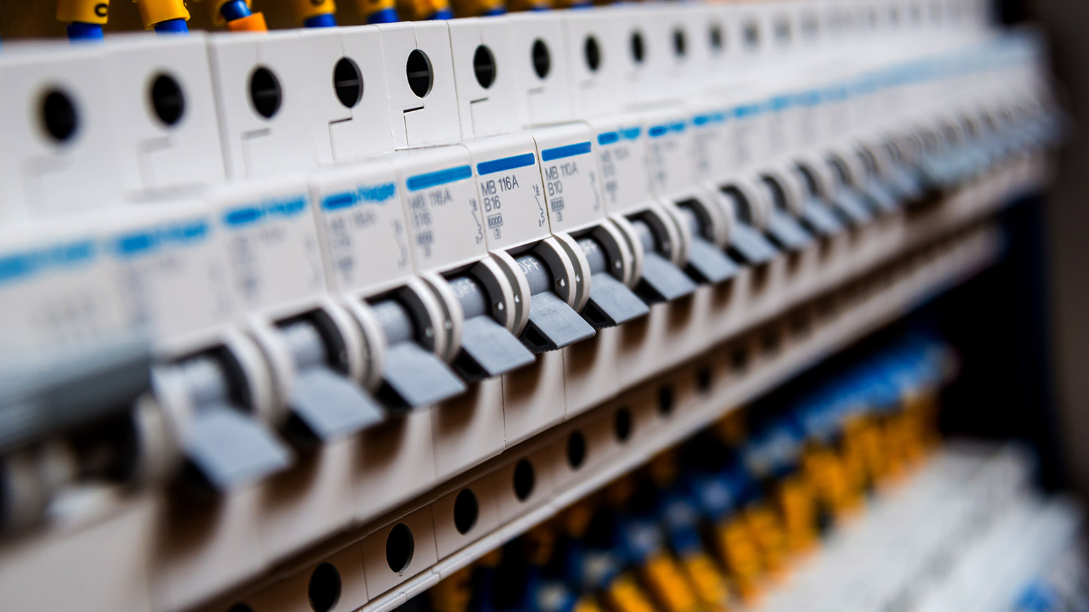
Miniature Circuit Breakers (MCBs)
Similar to a circuit breaker, an MCB will trip and break the circuit when the current exceeds a certain level. However, unlike a circuit breaker, an MCB is designed to protect a specific circuit or appliance, rather than the entire electrical system. It is typically installed in a distribution board or consumer unit. MCBs differ from traditional circuit breakers in their construction, size, and operating characteristics.
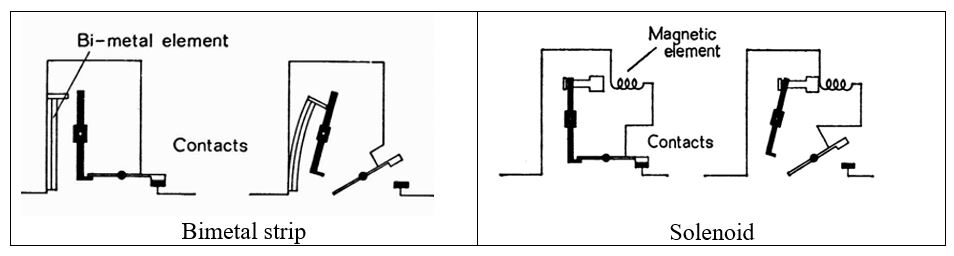
- Construction: MCBs are compact and designed to fit into standard electrical panel boards. They typically consist of an electromechanical trip unit and a thermal-magnetic overcurrent protection mechanism. The trip unit is activated by an electromagnetic coil or bimetallic strip when an overcurrent is detected, causing the circuit to be interrupted.
- Operating principles: MCBs operate on the principle of thermal-magnetic protection. The thermal protection element detects and responds to overloads, while the magnetic protection element detects and responds to short circuits. The trip unit is calibrated to respond to a specific overcurrent level, providing precise protection for the electrical circuit.
- Typical ratings: MCBs are rated based on their current-carrying capacity and breaking capacity. In New Zealand, MCBs are typically available with current ratings ranging from 1A -125A, and voltage ratings ranging from 240V - 415V.
- Applications: MCBs are widely used to protect residential, commercial, and industrial electrical circuits. They are commonly used in lighting, power, and control circuits, as well as motors, transformers, and other equipment. MCBs are also used in combination with other protection devices such as surge protectors and ground fault circuit interrupters (GFCIs) to provide more comprehensive protection for electrical systems.
MCBs are smaller and more compact than traditional circuit breakers, making them easier to install in standard electrical panel boards. They are designed to provide more precise protection for electrical circuits, with calibrated trip units that respond to specific overcurrent levels. They tend to be cheaper than traditional circuit breakers.
"How Circuit Breakers Work" by The Engineering Mindset - This video provides a detailed explanation of how circuit breakers work and includes animations to help visualise the process.
Activity
Refer to the diagrams in each case to answer the questions on this worksheet:
Activity

What we're covering:
- properties of fuses
- types of fuses
According to the New Zealand Wiring Rules, a fuse is a "device that is intended to open the circuit by fusing one or more of its specially designed and proportioned components when the current exceeds a given value for a sufficient time."
In other words, a fuse is a device that breaks an electrical circuit when it detects an overload or a short circuit. It contains a metal wire that melts and breaks the circuit when the current exceeds a certain level. The size and type of wire that is used in the fuse will dictate how much current can pass through that individual fuse. This is a one-time operation, and the fuse will need to be replaced before the circuit can be restored.
Fuses come in various sizes and ratings and are designed to protect electrical circuits and equipment from damage caused by overcurrent conditions, such as short circuits and overloads. When a fuse blows, it must be replaced with a new fuse of the same size and rating to ensure continued protection.

- Construction: Fuses consist of a fuse element, which is typically a wire or filament made of a metal such as copper or silver, enclosed in a protective housing. The housing is usually made of glass or ceramic to provide electrical insulation and mechanical protection.
- Operating principles: When an overcurrent or short circuit occurs, the current flowing through the fuse element causes it to heat up and melt, breaking the circuit and interrupting the current flow. The size and type of fuse element is selected based on the current rating of the circuit being protected, and the time-current characteristics of the fuse are designed to provide the appropriate level of protection.
- Typical ratings: Fuses are rated based on their current-carrying capacity, voltage rating, and breaking capacity. In New Zealand, fuses are typically available with current ratings ranging from a few milliamps to several thousand amps, and voltage ratings ranging from a few volts to several hundred volts.
- Applications: Fuses are used in a wide range of applications, including residential, commercial, and industrial settings. They are commonly used to protect lighting, power, and control circuits, as well as equipment such as motors, transformers, and generators. Fuses can also be used in combination with other protection devices such as circuit breakers, to provide more precise protection and reduce the risk of equipment damage and downtime.
Watch the Circuit Breakers and Fuses Explanation.
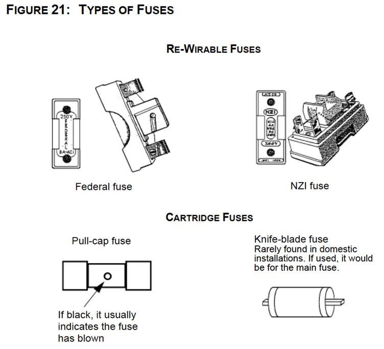
There are several types of fuses you are likely to encounter during your career:
Semi-Enclosed Wirable Fuses
This type of electrical fuse was commonly used in electrical installations in the past. It consists of a rectangular ceramic base with two or more terminals, which holds a replaceable fuse wire. The fuse wire is stretched between two terminals and clamped in place. The body of the fuse is typically open at one end, allowing the user to replace the fuse wire when it blows.
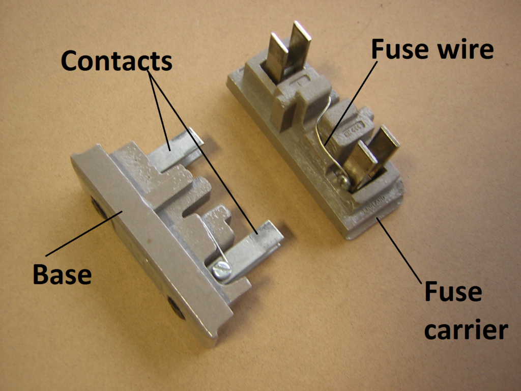
Sometimes referred to as a "Kit-Kat" fuse, since its shape resembles the chocolate bar, semi-enclosed rewireable fuses are becoming less common in modern electrical installations due to some limitations and disadvantages, including:
- Safety concerns: Fuses can expose the user to live parts and present a risk of electric shock. Arc flashes or fires may also occur when the fuse wire blows.
- Limited performance: Fuses have limited ability to interrupt short-circuit currents and may not provide reliable protection against overloads or earth faults.
- Inconvenient maintenance: Replacing the fuse wire requires manual intervention and can be time-consuming and inconvenient.
- Availability: Availability of the correct type and rating of replacement fuse wire can be limited.
Semi-enclosed rewireable fuses may still be used in certain applications, such as in older equipment or situations where replacement fuses need to be readily available.
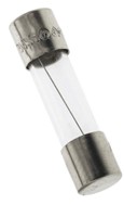
Cartridge Fuses
This type of fuse consists of a cylindrical body made of ceramic or glass, which contains a wire or filament that melts when exposed to excessive current flow. When the current flow exceeds the rated value, the wire or filament heats up and melts, breaking the electrical circuit and preventing further damage to the equipment or circuit. Cartridge fuses are available in various sizes and ratings and can be used for a range of applications, from low-voltage electronic circuits to high-voltage power systems.
High Rupturing Capacity (HRC) Fuses
HRC fuses are a type of cartridge fuse that have a high rupturing capacity, which means they can interrupt high fault currents without exploding or causing damage. This type of fuse has a ceramic body and contains a fuse element made of silver or copper. They are commonly used in industrial and commercial applications where high levels of fault current is present, such as in power distribution systems and motor control centres.
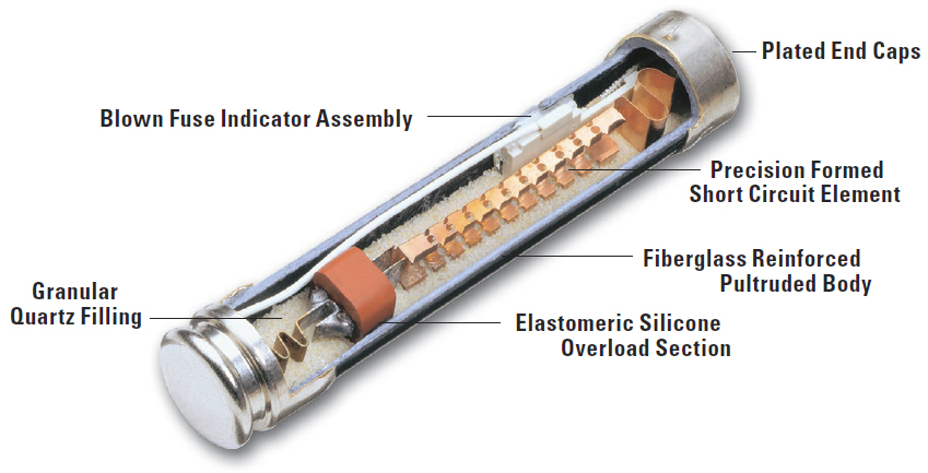
Watch the video showing what is inside an HRC fuse.
You may come across other types of fuses, including:
- Plug fuse: Used in older electrical installations to protect individual electrical outlets.
- Thermal fuse: Uses a thermal element to open the circuit when it overheats due to excessive current or temperature.
- Semiconductor fuse: Designed to protect electronic devices from overcurrent conditions. It contains a semiconductor element that melts when current levels exceed a certain threshold.
- Resettable fuse: Also known as a polyfuse or PTC (positive temperature coefficient) fuse, that can reset itself after a fault condition is cleared, making it suitable for applications where frequent overcurrent events occur.
- High-voltage fuse: Designed to protect high-voltage electrical systems from overcurrent conditions. They can handle high voltage and current levels.
The specific type of fuse used in an application depends on factors such as the voltage and current levels, the type of equipment being protected, and the required performance characteristics.
AS/NZS 3000:2018 provides guidelines and requirements for the installation of fuses and other electrical components. Consider the following when installing fuses:
- Fuse Rating: The fuse rating must be selected based on the expected current load and the protection requirements of the circuit. It is essential to ensure that the fuse's rating is not higher than the maximum current-carrying capacity of the wiring, as this can create a fire hazard. The fuse rating must also be selected to provide adequate protection against overcurrent and short-circuit faults.
- Fuse Type: The fuse type must be suitable for the application and installed in a manner that prevents damage to the fuse and the surrounding equipment. For example, if the circuit requires protection against earth leakage currents, a residual current device (RCD) must be installed instead of a standard fuse.
- Fuse Location: The fuse must be easily accessible and installed in a manner that prevents damage and minimises the risk of electrical shock. The fuse must also be located as close as possible to the source of power, to reduce the risk of damage to downstream equipment in the event of a fault.
- Fuse Replacement: Any replacement fuse must have the same rating and type as the original fuse. It is also essential to ensure that the replacement fuse is suitable for the application and is installed correctly.
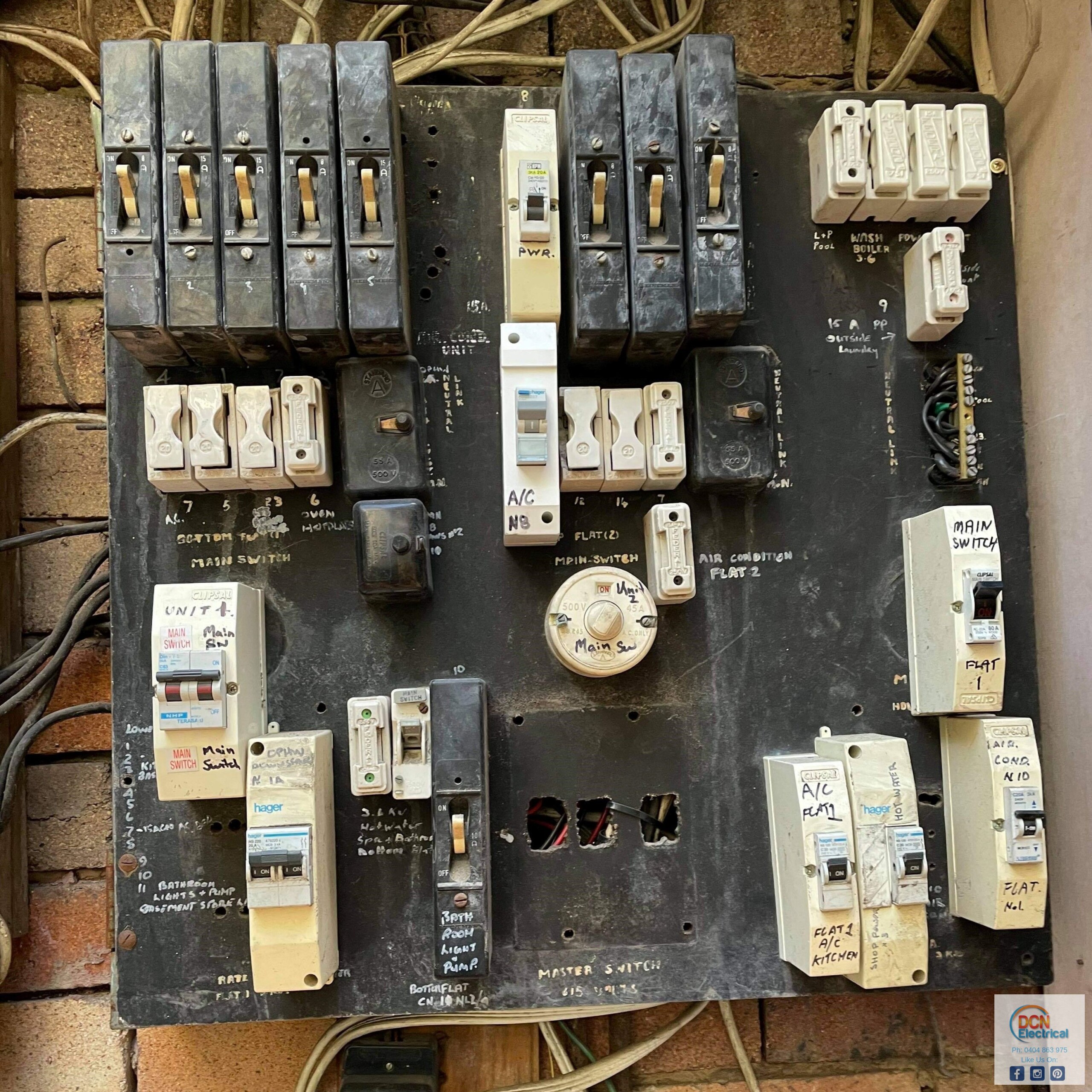
Fuse Boards
You may have come across a fuse board in an older electrical installation. Fuse boards contain several semi-enclosed rewireable fuses or cartridge fuses, that protect different circuits in the building. Each circuit is connected to a separate fuse that will blow if the current exceeds the rated value of the fuse. Fuse boards have been largely replaced by modern consumer units or distribution boards, containing MCBs and RCDs.
Activity
Answer the questions on this worksheet about fuses. Alternatively, you can complete the activity below.

What we're covering:
- components of RCDs
- uses of RCDs
An RCD is a safety device used to protect against electrical shock by interrupting the flow of electricity in the event of a ground fault. Also known as a safety switch, an RCD works by constantly monitoring the electric current flowing through a circuit. If it detects an imbalance in the current, which may indicate that electricity is flowing through a person instead of the intended path, it will quickly cut off the power supply to that circuit. RCDs are commonly used in homes, businesses, and industrial settings to help prevent electrocution and other electrical hazards.
- Construction: RCDs are made up of several components including a transformer, a sensing circuit, and a switching mechanism. The transformer works to create a magnetic field, which is then used to sense any current imbalance between the live and neutral conductors. If a current imbalance is detected, the switching mechanism will quickly interrupt the flow of electricity to prevent electrical shock.
- Operating Principles: RCDs operate on the principle of detecting a difference between the current flowing through the live and neutral conductors. This can occur when a person touches a live conductor or when there is a fault in an appliance or wiring that causes current to flow to earth. When this happens, the RCD will detect the imbalance and quickly disconnect the circuit, preventing electrical shock.
- Typical Ratings: In New Zealand, RCDs are typically rated between 10mA and 30mA. A rating of 10mA is common in areas where people are at higher risk of electrical shock, such as bathrooms, kitchens, and outdoor areas. A rating of 30mA is commonly used in other areas of a building where the risk of electrical shock is lower.
- Applications: RCDs are commonly used in a variety of applications, including homes, businesses, and industrial settings. In New Zealand, it is mandatory to have RCDs installed in new homes and any alterations or additions to existing homes must also have RCD protection installed. They are required by law to be installed in certain areas of a home, such as bathrooms, kitchens, and outdoor areas. It is recommended that portable RCDs be used for any outdoor electrical equipment, such as power tools or outdoor lighting, to provide additional protection against electric shock. In addition, RCDs are commonly used in commercial and industrial settings to provide protection against electrical hazards. They are often used in conjunction with other safety devices, such as circuit breakers and surge protectors, to provide a comprehensive safety solution.
Watch these videos explaining how RCDs work.
Activity

What we're covering:
- Type AC; A; and B RCDs.
According to Clause 2.6 of the New Zealand Wiring Rules there are three types of Residual Current Devices commonly used in New Zealand. These are:
- Type AC RCD.
- Type A RCD.
- Type B RCD.
Activity
This activity requires you to investigate the three types of RCDs.
- Begin by finding out what each of these RCD terms mean:
- Tripping characteristics.
- Sensitivity rating.
- Protection capabilities.
- Trip speed.
- Trip time.
- Rated current.
- Discrimination.
- Applications.
- Research the different types of RCDs - Type AC, Type A, and Type B, based on each of the terms in step 1 (Values will vary depending on the specific RCD model and installation conditions chosen. Make a note of your references used so that you can justify your answers.).
- Use the information to create a comparison table of the three types of RCD.
- Answer the questions below about the RCDs.
- Email your comparison table and your answers to the questions to your tutor, in preparation for a class discussion.
Questions
- Why is it important to use RCDs in electrical installations?
- Which type of RCD is the most sensitive and why?
- What is the purpose of discrimination in RCDs?
- What are the main differences between Type AC, Type A, and Type B RCDs?
- What are the key technical specifications that you should consider when choosing an RCD?
- In what types of electrical installations would you use a Type B RCD, and why?
- Which type of RCD would you recommend for a residential installation, and why?
- What are some common causes of unwanted tripping in RCDs, and how can you prevent them?
- What are some best practices for maintaining and testing RCDs in electrical installations?
- Why is it important to choose the right type of RCD for a particular application?

What we're covering:
- How surge protection devices are used
- Additional circuit protection
A surge protector is a device that protects electronic equipment from power surges caused by lightning strikes, power outages, or other sudden increases in electrical current. It combines both surge arresters and suppressors to provide comprehensive protection against momentary overvoltage.
Read about how a surge protector works on this page.
Construction: Surge protectors typically consist of three main components: the metal oxide varistor (MOV), the thermal fuse, and the surge protection indicator. The MOV is a device that conducts current when a voltage spike occurs, diverting the excess current away from the connected equipment. The thermal fuse is a safety feature that will cut off the current if the MOV gets too hot, preventing it from overheating and causing a fire. The surge protection indicator is a light or alarm that signals whether the surge protector is functioning properly.

Operating Principles: Surge protectors work by diverting excess electrical current to ground when a voltage spike occurs. When the voltage of the electrical system exceeds the level that the equipment can handle, the MOV conducts current and directs the excess energy to ground. The thermal fuse is designed to detect when the MOV is getting too hot and will disconnect the circuit if necessary to prevent the MOV from overheating.
Typical Ratings: The typical ratings for surge protectors in New Zealand include the voltage rating, which is usually 240 volts, and the energy absorption rating, which ranges from 200 to 1000 joules. The surge current rating is another important factor, which indicates the maximum amount of current that the surge protector can handle during a voltage spike.
Applications: Surge protectors are commonly used to protect electronic equipment in homes, offices, and other environments where electrical surges can occur. They are commonly used to protect computers, televisions, home theatre systems, and other sensitive electronic equipment. Surge protectors are also used to protect industrial equipment, such as motors, generators, and other heavy machinery.
Watch this video which looks inside a 13,500A surge protector.
Inside a 13 500A surge detector.
Activity
Additional Circuit Protection
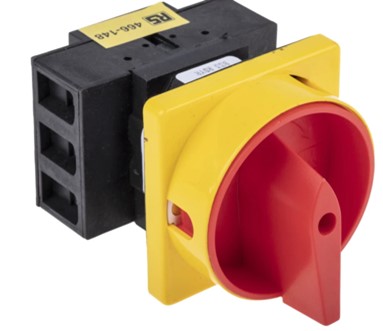
Isolators
Isolators, also known as isolation switches or disconnect switches, are electrical devices that provide a means of disconnecting an electrical circuit or appliance from the power supply. This is done using a switch or other similar mechanism that breaks the connection between the circuit or appliance and the power supply. Isolators are commonly used in electrical installations and systems to provide a safe and convenient means of disconnecting power for maintenance, repair, or safety purposes.
Construction: An isolator typically consists of a switch mechanism, an insulating enclosure, and terminals for connecting the circuit or equipment. The switch mechanism may be manual, operated by a handle or knob, or motorised, operated by a motor or solenoid. The insulating enclosure is usually made of non-conductive material, such as plastic or ceramic, and is designed to prevent accidental contact with live parts. The terminals are usually designed to accept cables or busbars and may be rated for different current and voltage levels.
Operating principles: Isolators work by providing a means of opening or closing a circuit, and physically isolating the circuit or equipment from the power source. When the isolator switch is in the closed position, the circuit is connected to the power source and can operate normally. When the isolator switch is in the open position, the circuit is disconnected from the power source and is isolated for maintenance or safety purposes.
Typical ratings: Isolators are available in a range of ratings, depending on their intended application. Some typical ratings include:
- Voltage: from low voltage (e.g., 12V) to high voltage (e.g., 1000V or more)
- Current: from a few amps to several thousand amps.
- Frequency: typically rated for 50Hz or 60Hz but may be rated for higher frequencies in some applications.
- Short-circuit current rating: the maximum current that the isolator can safely interrupt without damage.
Applications: Isolators are commonly used in a variety of applications, including:
- Electrical installations: to provide a safe means of disconnecting power for maintenance or repair.
- Industrial equipment: to isolate machines or equipment for maintenance or safety purposes.
- Power distribution: to isolate sections of a power grid or distribution network for maintenance or repair.
- Renewable energy systems: to isolate solar panels or wind turbines for maintenance or repair.
- Safety systems: to provide an emergency means of shutting down power in case of an emergency or fault.
Voltage regulators
Although not specifically designed as circuit protection devices, voltage regulators can help to protect electronic devices from overvoltage and undervoltage conditions by regulating the voltage output of a power supply to provide a stable and consistent voltage level, regardless of changes in input voltage or load current.
Construction: Voltage regulators typically consist of a voltage reference, an error amplifier, a series pass element, and feedback and control circuits. The voltage reference sets the desired output voltage, and the error amplifier compares the actual output voltage to the reference voltage and generates an error signal. The series pass element adjusts the output voltage to correct for the error, and the feedback and control circuits stabilise the voltage output.
Operating principles: Voltage regulators work by regulating the output voltage of a power supply or battery to a specified level, regardless of changes in input voltage or load current. The regulator maintains a constant output voltage by comparing the actual output voltage to a reference voltage and adjusting the series pass element to correct for any errors.
Typical ratings: Voltage regulators are available in a range of ratings, depending on their intended application.
Applications: Voltage regulators are commonly used in a variety of applications, including:
- Electronic equipment: to regulate the voltage of power supplies for computers, televisions, and other consumer electronics.
- Power grids: to regulate the voltage of power transmission and distribution systems.
- Renewable energy systems: to regulate the voltage of solar panels and wind turbines.
- Automotive and aerospace systems: to regulate the voltage of batteries and electrical systems in vehicles and aircraft.
- Industrial and manufacturing equipment: to regulate the voltage of power supplies for machinery and equipment.

What we're covering:
- designing a circuit protection plan
The objective of this activity is to design an appropriate circuit protection plan for a typical residential electrical system in New Zealand.
Activity
Instructions:
- Select the appropriate circuit protection devices to be installed based on the information provided.
- Research and apply relevant New Zealand standards, such as the Electrical Code of Practice and the Wiring Rules.
- Present your findings in a table as shown.
Specifications:
- Service voltage: 230VAC
- Service current: 100A
- Number of circuits: 20
- 10 lighting circuits (10A)
- 3 appliance circuits (16A)
- 3 socket-outlet circuits (20A)
- 2 HVAC circuits(16A)
- 2 hot water cylinder circuits (20A)
- Expected loads: lighting, appliances, electronics, heating, and cooling.
- Lighting: 2,500W
- Appliances: 4,800W
- Socket-outlets: 4,800W
- HVAC: 6,400W
- Hot water cylinder: 4,800W
Example Table
| Device | Placement | Type of Circuit | Rating | Purpose | Cost |
|---|---|---|---|---|---|
You can download a copy of the table template here.

What we're covering:
- switchboards
- types of fuses used in New Zealand
- changing a fuse
The switchboard in a home protects the electrical wiring system. It is comprised of a main power switch and several fuses or circuit breakers, each corresponding to a different area of wiring in the house. If an electrical fault occurs, the corresponding fuse will blow, or the circuit breaker will trip to prevent overloading or fire hazards.
Semi-enclosed rewireable fuses (SERFs) were once a common type of fuse used in electrical installations in New Zealand. However, as of 2018, they are no longer permitted for new electrical installations or for replacement of existing SERFs in certain situations due to safety concerns and the availability of newer and safer types of fuses.
Watch the following videos which demonstrate how to change a fuse, should the situation arise with an old switchboard.
Activity
Activity
As an electrical apprentice, you are asked to inspect an electrical installation that still uses fuses. Write a report on the potential hazards that may arise from using fuses instead of mini circuit breakers and the benefits of upgrading to mini circuit breakers. Your report should include information about:
- Potential hazards associated with using fuses instead of mini circuit breakers
- Benefits of upgrading to mini circuit breakers
Post your report on the class forum when you are complete. Make sure you read and comment on some of your classmate's reports.
Replacing rewireable fuses with plug-in circuit-breakers
Rather than replacing fuses, you are likely to be called upon to replace rewireable fuses with circuit-breakers. Refer to Appendix A5 in the New Zealand Electrical Code of Practice for Homeowner/Occupier’s Electrical Wiring Work in Domestic Installations to answer the following questions.
Activity
- Rewireable fuses can be replaced with plug-in circuit-breakers, as long as the fuse base: (Identify the three reasons)
- Answer the following questions about the correct fuse/circuit-breaker match.
- What is the recommended circuit-breaker amperage for a 5A fuse?
- Which fuse amperage should be paired with a 20A circuit-breaker?
- What circuit-breaker amperage is suitable for a 30A fuse?
- Can a 15A fuse be paired with a 20A circuit-breaker?
- Is it safe to pair a 10A fuse with a 16A circuit-breaker?
- What should you do if you want to have the 30-amp rewireable fuse for an electric range replaced with a circuit-breaker?
When you have finished, email your answers to your tutor.

What we're covering:
- mechanical switches
- Electrical switches
- Relays
- Transistors
- Diodes
Switches are categorised based on their mode of operation. The two main categories of switches are mechanical switches and electrical switches.
Mechanical switches
Mechanical switches are physical devices that use mechanical force to create a connection, or break an existing connection, between two electrical terminals. They typically have a physical lever, button, or knob that is moved to open or close the contacts of the switch. Mechanical switches are often preferred for their simplicity, durability, and low cost. They are commonly used in applications that require a physical switch to be operated, such as light switches or doorbells. Their drawbacks include limited switching speed and susceptibility to wear and tear over time.
Activity
Switches 1 and 2 in the diagram below are SPDT type switches. Complete the following table.
Electric switches
Electric switches are switches that use an electrical signal to control the flow of electricity. They include solid-state switches, such as transistors, diodes, and thyristors, as well as electromechanical switches, such as relays and contactors. Electric switches do not require any physical movement of a lever or button, but instead rely on changes in voltage, current, or magnetic fields to create the connection or break it.
Electric switches are often preferred for their high switching speed, precision, and reliability. They are commonly used in complex electronic circuits, such as computer processors, where fast and accurate switching is essential. Electric switches can be more expensive and complex to use than mechanical switches and may require additional components such as transistors and diodes to function properly.
Relays
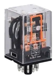
Relays are electrically operated switches that open and close the circuits by receiving electrical signals from outside sources. For example, when you push the button on a TV remote to watch TV, it sends an electrical signal to the “relay” inside the TV, turning the main power ON.
Relays use an electromagnetic coil to control the position of a set of contacts, which can be either normally open (NO) or normally closed (NC). When the coil is energised, the movable armature or plunger is pulled towards it, causing a set of contacts to either open or close, depending on their initial state. This allows the relay to switch a higher voltage or current than what is required to activate the coil. Relays can be used to switch on or off motors, lights, and other electrical loads.
Watch this video which explains how relays work.
Transistors
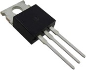
A transistor is a semiconductor device that is commonly used in electronic circuits for amplifying or switching electronic signals. It consists of three layers of semiconductor material, two of which are doped with impurities to create regions called the emitter (e) and the collector (c). The third layer, known as the base (b), is sandwiched between the emitter and collector layers.
In its simplest form, a transistor acts as a switch by controlling the flow of current between the emitter and collector terminals. This is done by applying a small current or voltage to the base terminal, which acts as a control signal. When the control signal is applied, it causes a large current to flow between the emitter and collector terminals, effectively turning the transistor "on" or "off".
The two most common types of transistors are PNP and NPN, which refer to the type of semiconductor material used in the emitter and collector layers.
In a PNP transistor, the emitter is made of a negatively charged material and the collector is made of a positively charged material.

In contrast, an NPN transistor has an emitter made of a positively charged material and a collector made of a negatively charged material.

To use a transistor as a switch, the base terminal is typically connected to a control circuit that supplies a voltage or current signal to turn the transistor on or off. In this configuration, the collector and emitter terminals act as the switch contacts, allowing current to flow between them when the transistor is turned on and blocking current when the transistor is turned off.
When a small electric current is sent to the base of the transistor, it acts like a gate that allows a larger current to flow from the collector to the emitter. This is because the current flowing through the base creates a sort of bridge between the collector and emitter, allowing the larger current to flow through the transistor.

By controlling the amount of current sent to the base, we can control how much current flows through the transistor. This makes transistors useful as switches in electronic circuits. When no current is sent to the base, the transistor is turned off and does not allow any current to flow. When a small amount of current is sent to the base, the transistor turns on and allows a larger current to flow through it, acting like a switch.
Transistors are used in a wide range of devices, from radios and televisions to computers and mobile phones.
Read more about how transistors work here.
Watch this video which provides some extra information on transistors and how they work.
Diodes
A diode is an electronic component that allows current to flow in only one direction. It is made of a semiconductor material and has two terminals called the anode and cathode. When a voltage is applied to the anode of a diode that is greater than the voltage at the cathode, the diode conducts electricity and allows current to flow through it. However, when the voltage at the cathode is greater than the voltage at the anode, the diode does not conduct electricity and blocks the flow of current.
This property of a diode makes it useful as a switch. By placing a diode in series with a load, the flow of current can be controlled. When the voltage is applied in the forward direction, the diode conducts, and the load receives power. When the voltage is applied in the reverse direction, the diode does not conduct, and the load does not receive power.

Diodes are also used in rectifier circuits, which convert alternating current (AC) to direct current (DC). In a rectifier circuit, a diode is placed in series with an AC voltage source. The diode conducts when the AC voltage is positive, allowing current to flow in one direction, but blocks current flow when the AC voltage is negative, preventing current from flowing in the opposite direction.
Watch this video which provides some extra information on diodes and how they work.

What we're covering:
- Thyristors
- Checks and tests
Thyristors
A thyristor is another electronic component that can act like a switch. It is made up of four different parts called the anode, cathode, gate, and the trigger electrode.

When a small signal is sent to the gate, it allows a larger amount of electricity to flow through the thyristor. This is kind of like a "switch" turning on - the thyristor lets electricity flow through when the gate receives a signal.
Once the thyristor is "on", it stays on until the electrical current flowing through it drops below a certain level. This means that it can keep letting electricity flow even if the signal that turned it on has stopped.
Thyristors are useful in electronic devices that need to control the flow of electricity, like dimmer switches or motor controllers. They can handle a lot of electrical current and are very reliable.
Watch this video explaining how thyristors work.
What is a Thyristor? How Thyristors Work?
Activity
Checks and Tests
Once a lighting circuit has been installed, a series of tests must be carried out to ensure that it is functioning correctly and is safe to use. Refer back to previous notes about inspection and testing. These tests include:
- Visual Inspection involves ensuring that the installed circuit and all its components comply with the AS/NZS 3000:2018 clause 8.2.2 checklist and other relevant standards. Wires must be properly routed and supported, the correct size and type of cable must be used, and all connections must be properly made and secured. The visual inspection also ensures that there are no visible signs of damage or wear and that all electrical equipment used in the installation is marked with an appropriate rating. Lamps should be installed to avoid excessive temperature increases, ignition, or degradation of materials.
- Insulation and Continuity Testing is performed using an insulation tester, such as a digital multimeter, to measure the level of insulation present in the circuit, and to indicate whether there is any break in the circuit. Set the insulation tester to the 500V range and test between the conductors. The insulation resistance should be infinity. Refer to AS/NZS 3000:2018 clauses 8.3.5 and 8.3.6 for more detail.
- Earth Fault Loop Impedance testing is carried out to determine the ability of the circuit's protective devices, such as fuses and circuit breakers, to operate quickly enough to prevent a dangerous electric shock. This test involves applying a voltage to the circuit and measuring the resistance of the earth fault loop. The reading obtained is then compared to the maximum values in Table 8.1 of AS/NZS 3000:2018. Refer also to clause 8.3.9. for more information.

What we're covering:
- uses and operation.
- key components
In the world of electrical control systems, simple on-off switches are not enough for most processes. They require advanced control systems to manage commands, direct actions, and regulate device behaviour. This is where electromagnetic relays, programmable relays, and programmable logic controllers (PLCs) come in.
Relay logic control (RLC) uses relays as key components. Relays are devices that switch electrical circuits based on external signals. With relay logic, engineers create control systems that handle tasks and ensure proper equipment function.
Electromagnetic relays utilise the principles of electromagnetism to control circuits. They consist of a coil and contacts, where the coil generates a magnetic field that controls the opening and closing of the contacts. Key features of electromagnetic relays include simplicity, reliable switching performance, and widespread application in various control systems.
Programmable relays, also known as solid-state relays or smart relays, offer the advantages of electromagnetic relays while incorporating programmable logic capabilities. By integrating microcontrollers and digital circuitry, programmable relays can be programmed to perform specific control tasks. Their key characteristics include programmability, compact size, and additional features such as time delay, counters, timers, and logic functions.
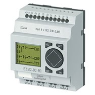
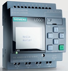
Programmable logic controllers (PLCs) revolutionised automation by combining microcontrollers and solid-state switching. Unlike relay logic, PLCs can be programmed for specific tasks, offering flexibility and customisation. By using software, PLCs handle complex processes, follow instructions, and integrate with other systems.
PLCs represent a highly advanced form of control system technology. They encompass a comprehensive range of features and capabilities for automation and control. Key attributes of PLCs include powerful computing capabilities, extensive input/output options, and the ability to integrate with various systems. PLCs offer unparalleled flexibility, adaptability, and the capacity to handle intricate processes.
While relays, programmable relays, and PLCs handle control and switching, they differ in functionality and capabilities. Electromagnetic relays are reliable and simple, suitable for basic tasks. Programmable relays offer flexibility, programmability, and additional features, but are less powerful than PLCs. PLCs are at the forefront of automation, providing advanced computing capabilities, extensive customization options, and the ability to handle complex control strategies.
Activity
Watch these informative videos about Relay Systems.
What is a Relay System?
What Are the Advantages PLCs Have over Relay Systems?
Operation of Programmable Relays and PLCs
Programmable relays and a programmable logic controllers (PLCs) serve similar functions but differ in terms of complexity and capabilities. Programmable relays are simpler devices with limited functionality compared to PLCs, which offer more advanced capabilities, such as communication modules and integrated programming and HMI features. A table comparing the parts of each system is shown here:
| Parts | Programmable Relay | Programmable Logic Controller |
|---|---|---|
| Power supply | Provides electrical power to the relay | Supplies power to all components of the PLC |
| Input module | Receives signal from external devices | Receives signal from sensors and devices |
| Processor module | Executes control program and makes decisions | Acts as CPU, executing control instructions |
| Memory module | Stores control program and data | Holds program, data and retains information |
| Output module | Transforms control signals into physical actions | Converts control signals to control outputs |
| Communication modules | N/A | Enables connectivity with other devices/systems |
| Programming and HMI | N/A | Software for programming & monitoring the PLC |
PLCs and programmable relays have distinct differences in functionality, programming flexibility, processing power, communication and integration capabilities, as well as scalability and expandability.
PLCs are advanced control systems designed for complex automation tasks. They feature a dedicated CPU, expanded input/output options, and sophisticated programming and HMI features. PLCs excel in handling larger-scale processes and integrating with various systems. They offer extensive programming options, powerful processors, and the ability to communicate with other devices and systems. Moreover, PLCs can be easily expanded to accommodate evolving control requirements.
In contrast, programmable relays are simpler devices suitable for straightforward control applications. They have basic programmability and control capabilities. Programmable relays offer limited functionality, basic programming options, and less processing power compared to PLCs. Their communication capabilities are also more limited, and they may lack extensive integration capabilities. Additionally, programmable relays may have constraints when it comes to scalability and expandability.
Control Programmes for Switching and Controlling Loads
A control programme for switching and controlling loads refers to a software-based solution designed to manage and manipulate various electrical loads in a system. It provides a means to control the operation of loads, such as lights and motors, by sending commands to switches, relays, or other control devices. The control programme acts as an intermediary between the user and the devices, making load control easier and more efficient.
Design of an Entry-Level Control Programme
An entry-level control programme is typically designed with the objective of providing a user-friendly interface that simplifies load switching and control. To achieve this, the programme incorporates several key design elements:
- Graphical User Interface (GUI): The control programme utilizes a graphical user interface that allows users to interact with the system easily. The GUI presents a visual representation of the loads, providing intuitive controls such as buttons, sliders, or checkboxes. This visual interface makes it simpler for users, even those with limited technical knowledge, to understand and operate the programme effectively.
- Load Configuration: The control programme provides a mechanism for users to configure and define the loads they want to control. This includes specifying the type of load (e.g., lights, motors, heaters) and assigning unique identifiers or names to each load. Additionally, users may be able to set parameters such as voltage levels, current limits, or scheduling options for individual loads.
- Communication Interface: To enable interaction with physical devices, the control programme incorporates a communication interface. This interface allows the program to communicate with external devices like relays, switches, or sensors, which are responsible for the actual switching and control of the loads. The interface may utilize protocols such as Modbus, Ethernet, or wireless technologies to establish communication between the programme and the devices.
Function of an Entry-Level Control Programme
The primary function of an entry-level control programme is to provide a simplified yet effective means of switching and controlling loads. The programme performs several essential functions to achieve this goal:
- Load Monitoring and Status Display: The control programme continuously monitors the status of the connected loads, providing real-time feedback on their operational state. It displays this information on the GUI, allowing users to quickly identify which loads are powered on or off. This feature enhances safety and facilitates troubleshooting by enabling users to identify potential issues at a glance.
- Load Switching and Control: The control programme enables users to switch loads on or off conveniently through the GUI. By interacting with the graphical controls, users can send commands to the connected devices, activating or deactivating the respective loads. This functionality allows for efficient and centralized control of multiple loads from a single interface, reducing the need for manual intervention.
- Load Scheduling and Automation: An entry-level control programme often includes scheduling and automation capabilities. Users can define specific time-based or event-based scenarios for load control. For instance, they can schedule lights to turn on or off at specific times or trigger load control based on environmental factors or sensor inputs. This automation enhances energy efficiency, convenience, and overall system management.
- Alarms and Notifications: To ensure effective load management, the control programme can generate alarms or notifications for critical events or abnormal conditions. For example, it can alert users when a load exceeds a specified current limit, indicating a potential fault. These notifications help in prompt troubleshooting and maintenance, preventing potential damage.
Activity
Consider the following questions. Post your ideas on the class forum for discussion.
- What are the key characteristics of entry-level control programmes for programmable relays?
- How do entry-level control programmes for programmable relays function?
- What is the purpose of entry-level control programmes for PLCs?
- Describe the design approach of entry-level control programmes for PLCs.
- How do entry-level control programmes for PLCs differ from those for programmable relays?
What we're covering:
- What PELV and SELV systems are
The Electricity (Safety) Regulations 2010, define extra-low voltage (ELV) as any voltage normally not exceeding 50 volts AC or 120 volts ripple-free DC. According to AS/NZS 3000:2018, ELV electrical installations shall be one of two systems - Separated Extra-Low Voltage (SELV) and Protective Extra Low Voltage (PELV).
Find the definition of each system in the Wiring Rules and complete the sentences:
Activity
Watch this video to learn about SELV and PELV transformers.
SELV and PELV what is it?
SELV Systems
In a SELV system, the voltage is limited to a level that is considered safe for humans even under fault conditions, such as when a short circuit occurs. This is achieved by using a transformer or power supply that isolates the circuit from the main power supply and provides a low voltage output that is isolated from the mains supply.

Notice there is an earth connection on the primary winding, but not on the secondary winding. It is separated from earth, hence the name – separated extra low voltage. Protective earth conductors are NOT permitted to be installed on the secondary SELV side of the transformer.
Because there is no earth reference on the Secondary side it is unlikely that a person will receive an electric shock from a single fault on the secondary side. As there is no earth reference, there is no electrical path for the electrical fault current to flow, hence, no shock.
Some SELV transformers do not have an earth connection to the primary side either. These can be identified by the Double Insulated logo on the outside of the casing and the absence of an earth in the mains cable.

SELV systems are designed to minimise the risk of electric shock in high-risk situations by limiting the voltage and current levels of the power supply. One typical application is Zone 0 in a swimming pool zone - which is in the water container itself. A transformer is used to reduce the mains voltage to a low voltage of 12 volts AC. The low voltage electrical circuit is then used to power the pool lights, which are installed underwater. The SELV system ensures that even if there is a fault or a failure in the lighting system, the low voltage levels will not pose a risk of electric shock or fire.
SELV systems are also used in:
- Bathroom lighting.
- Outdoor lighting.
- Cordless hand tools.
- Medical equipment, especially equipment that patients come in contact with, such as electrocardiographs and defibrillators.
- Telecommunications equipment particularly equipment that is used in wet or humid environments, such as marine communication equipment.
Activity
Discuss the requirements for SELV circuits in terms of insulation and separation from other circuits. Email your findings to your tutor. (Refer to AS/NZS 3000:2018 Clause 7.5.5 for guidance.)
PELV Systems
PELV also refers to circuits that operate at a voltage level safe for humans to touch. In contrast to a SELV circuit, a PELV circuit can have a protective earth connection. Otherwise the PELV system meets all SELV requirements. Protection by PELV is used where extra-low voltage is required, but the risk of electric shock is much lower than what would be expected for a SELV wiring situation.

PELV systems typically consist of a safety isolation transformer is commonly employed to provide electrical separation from the low voltage wiring system on the primary side, with the addition of circuit protection in the secondary conductors of the ELV circuit.
A PELV circuit only requires protective separation from all circuits that might carry higher voltages, but it may have connections to other PELV systems and earth.
These circuits are typically used in applications where there is a risk of electrical shock, such as in medical equipment or in areas where water is present. An example of a PELV system is the use of low voltage electrical circuits in a hospital operating room. In this application, a transformer is used to reduce the mains voltage to a low voltage of 120 volts AC. The low voltage electrical circuit is then further reduced to 25 volts AC by a secondary isolating device. The PELV system ensures that even if there is a fault or a failure in the electrical system, the low voltage levels will not pose a risk of electric shock or fire. Other applications for PELV systems include:
- Garden lighting.
- General ELV lighting.
- Automation busways.
- ELV machine control circuits.
Activity
Discuss the requirements for PELV circuits in terms of insulation and separation from other circuits. Email your tutor. (Refer to AS/NZS 3000:2018 clause 7.5.5 for guidance.)
Activity
Refer to AS/NZS 3000:2018 Clause 7.5.7 to 7.5.11, and clause 8.3.3.2 to complete this worksheet.
Activity
Discuss the consequences of non-compliance with the requirements for extra-low voltage electrical installations, as per Clause 7.5 of the AS/NZS Wiring Rules.
Complete any outstanding assessment tasks for this module.