In this topic we’ll:
- introduce you to SketchUp for the Web and walk you through the process of setting up a free account and logging in
- show you how to move around in three-dimensional (3D) space in SketchUp
- cover the main 3D modelling tools and demonstrate how to:
- bring in your base plan and concept sketches as reference drawings
- draw your rough concept
- create 3D buildings and hard landscaping
- import models from the SketchUp 3D Warehouse to add plants and people to your model
- explore the model to identify and resolve design problems.
By the end of this topic you’ll be able to:
- Create a 3D model of a design concept for your site which includes 3D buildings and landscaping elements.
This topic focuses on using SketchUp, rather than the landscape design process. We suggest you go back to the previous topic on concept refinement when you start using SketchUp to refine your design.
As mentioned earlier, we’ll be using a free CAD application called SketchUp for the Web, made by Trimble. As its name suggests, you don’t need to download anything because it runs in a web browser.
If you have used SketchUp before and have a Timble account, jump ahead.
Creating a Trimble account
To get started you’ll need to:
- Click on the following link: SketchUp for the Web
- Click the ‘Start Modelling’ button.
- If you haven’t used SketchUp before, on the sign in page click the text which reads ‘Create a Trimble ID’ and choose “Everywhere else” for your region, then click the ‘Next’ button.
- Follow the steps to set up your account.
Logging in to SketchUp for the Web
To log in to the web application:
- Go to: https://app.sketchup.com/app
- Use the username and password you just set up to log in and complete the two-factor authentication by using the number that has been sent to you in a text message or email.
- You should see the home screen, as shown below.
- Click either the ‘Start modelling’ or ‘Create new’ button.
On your first visit, or when new features have been added, you may be given a demo. Read the text bubble and then click the ‘Okay!,’ ‘Next’ or ‘Got it!’ button to go to the next step. Click the X icon in the top right corner of floating windows to close them.
Kicking off on the right foot
The following video from SketchUp School (14:19 minutes) introduces seven key things you’ll want to know before you start working on your own designs in SketchUp of the Web.
Watch: Watch This Before You Get Started with SketchUp – 7 Essential Tips (2023 Update)
In the video Alex made the following points:
- Start in 2D (plan view). From the right hand menu the scenes button (the movie clapboard icon), click ‘Standard Views’ and then ‘Plan View (Top).’
- Use a three-button mouse (one with two main buttons and scroll-wheel that can be clicked in as a third button). If you don’t have one you can get by using the following keyboard shortcuts, but if you plan on using CAD often, a good mouse is a worthwhile investment:
- O = Orbit
- H = Pan (H for the hand icon, and because P is already used for the Push/Pull action)
- Z = Zoom
- Press the relevant key and then click and hold the left mouse button to perform the action.
- Most of the tools (actions) in SketchUp are designed to be done in the following order:
- Choose the tool from the left hand menu or by pressing the relevant shortcut key, like R for the rectangle tool or L for the line tool.
- Click and release the left mouse button (“left click”) at the point you want to start the action.
- Move the mouse cursor to the point you want to finish the action.
- Left click.
- Geometry – endpoints, edges, and faces in SketchUp – stick to each other. This is referred to as “sticky geometry.”
- If you don’t want an object to stick to another one, turn the object into a group or a component.
- The easiest way to do this is to click the left mouse button three times quickly on one part of the object you want to protect. The triple-click tells SketchUp to select all geometry that is connected to the bit you’re clicking on.
- Right click on the geometry you have selected and choose either “Make Group” or “Make Component.”
- We’ll talk about the difference between groups and components later, but for now, either will work.
- Use the move tool correctly:
- Select the move tool.
- Identify the part of the object you want to move to the desired location – usually an endpoint or a midpoint.
- Left click at that point.
- Move the object to the new location with the mouse.
- Left click.
- If you press the Control (“Ctrl”) key on your keyboard after your first click but before your second click, SketchUp will create a copy of the object. Click a second time to place this copy.
- Get good at using the zoom, orbit, and pan tools using either:
- Your three-button mouse:
- Scroll wheel to zoom
- Clicking the scroll wheel in to orbit
- Clicking the scroll wheel in and holding the Shift key to pan.
- The O, H, and Z shortcut keys mentioned above.
- Your three-button mouse:
One other thing you’ll find extremely useful is the Instructor. Click on the graduation cap in the right hand menu. Now choose a tool from the left hand menu. Whatever tool you choose, the Instructor window will explain how to use that tool, including more advanced features.
Activity: First steps with CAD
Before you can run you need to learn to walk. This exercise will help you get to grips with the basics.
- Create a new drawing in SketchUp.
- Left click on the person and then press the Delete key.
- Go to Plan View.
- Use the Rectangle tool to create two overlapping rectangles.
- Use the Eraser tool to erase the lines in the middle so it forms one shape.
- Make the shape into a Group.
- Use the Line tool to draw a triangle with one edge touching the other shape.
- Make the triangle into a Component.
- Use Orbit, Zoom, and Pan to move the view so you see the objects in a perspective (3D) view.
- Use the Move tool to create a copy of the rectilinear object, by clicking the Ctrl key once you have started the move action.
- Use the Move tool to make a copy of the triangle but this time constrain the movement to the red or green axis by pressing the left or right arrow after pressing Ctrl.
- Click the ‘SAVE’ button at the top left and save this file. If you get a message about purging unused items click the ‘Yes, purge all’ button.
Here is a short video (1:23 minutes) showing these steps.
Congratulations, you’ve created your first models in CAD!
Understanding three-dimensional space
Any point (P) in three-dimensional space can be described by its coordinates: P = x, y, z. The x and y coordinates are perpendicular directions on a flat surface. In SketchUp, the y (green) direction relates to north and south by default, and the x (red) direction relates to east and west. A better use is to use the green and red axis to align with the walls of your main building.
The z (blue) direction relates to the height of the point, e.g. 1.2m above the ground.
The point where the coordinates are P = 0, 0, 0 is where the three axes intersect and is called the origin. You can usually see the origin in SketchUp.
As already mentioned, we can constrain (limit) our actions along one of these directions by pressing the relevant arrow key after we start an action. For example to draw a line that points directly north we:
- press L to activate the Line tool
- left click at our starting point
- press the left arrow
- move the mouse cursor to our end point
- left click to finish the action
- press escape if you don’t want to draw another section of line.
You can constrain the direction in any of the three axis directions using following keys:
- Left arrow = slide the object along the green axis
- Right arrow = slide the object along the red axis (“for red, use right”)
- Up arrow = blue axis (the blue axis generally means up and down).
Accuracy and dimensions
Click the three horizontal lines at the top left to access the dropdown menu and click on ‘App Settings.’ On the General tab, under “Regional” make sure the Default template is set to “Decimal - Millimetres.” Click the X in the top right corner to close this window.
When performing an action, use the number keys to type in the dimension you want. For example, to draw a line that is 2m long, start a line and move the mouse in the direction you want it to go. Constrain the line along the red, green, or blue direction if needed. Type in “2000” (because our workspace is set to Millimetres) or type “2m” and then press enter.
If you want to draw a rectangle that is 1.2 x 2.8m type “1200, 2800” and press enter.
Use the tape measure (shortcut = T) to measure distances and create guides. To create a guide click on a line (edge) and drag in the direction you want the guide to be. Use the relevant arrow key to constrain the direction to one of the axes. Type in the distance from the line that you want to guide to be placed.
Working smarter not harder
You can access almost all of the tools in SketchUp by using shortcut keys on your keyboard. Doing so will really speed up your work. Try to use the following six, as these cover about 80% of the actions you’ll do in SketchUp:
- E = Eraser
- L = Line
- M = Move
- P = Push/Pull
- R = Rectangle
- Spacebar = Select.
Watch: SketchUp Tutorial for Beginners - Learn SketchUp in 10 MINUTES
Start a new SketchUp file and then watch the video from MasterSketchUp (10:16 minutes).
Try and follow along with Matt and model the table. Matt uses imperial units (inches and feet), but you could choose to swap that for metric measurements instead, for instance 450mm rather than 18”.
The two videos from SketchUp School and MasterSketchUp have introduced most of the basics of using SketchUp, but we’ll expand on these briefly now.
Using the selection tool
Select objects with the select tool (shortcut = Spacebar), then use one of the following methods:
- Drag a rectangle from left to right to select only the objects fully enclosed by the selection rectangle.
- Drag a rectangle from right to left to select all objects that are fully or partially enclosed by the selection rectangle.
- Click once on an object (edge, face, component, or group).
- Double-click a face to select the face and all of its edges.
- Double-click an edge to select the edge and the faces that share it.
- Triple-click an edge or face to select all connected items.
- Click on one object then hold down the Shift key and click on other objects to select multiple objects.
Activity: Groups and components
We’re going to look at the difference between groups and components.
- Open the SketchUp file that you created in our last activity – the one that has two rectilinear shapes and two triangles.
- Click the Outliner button (the icon that looks like an organisational structure diagram) on the right hand menu.
- You should see two items in the list that have two cubes surrounded by a dashed line and say Group next to them. These are Groups.
- You should also see two items that have an icon made up of three or four cubes. These are Components.
- If you don’t have two Groups and two Components, delete all of the items and repeat the previous activity.
- Double-click on one of the rectilinear shapes to enter the group so you can edit it.
- Use the Push/Pull tool (shortcut = P), click on the face, move your mouse up and click again to finish the action. Your two-dimensional (2D) shape is now a 3D form!
- Use the Select tool (shortcut = Spacebar) and click outside the dashed box to exit the group.
- Now double-click on one of the triangles to enter the component so you can edit it.
- Use the Push/Pull tool to move the face up and click to save it.
- Use the Select tool and click outside the dashed box to exit the component.
- Click the “SAVE” button.
Was there any difference when you edited the component compared to editing the group?
You should have found that when you edited the triangle the other triangle changed too. This is because when you copy a component it effectively creates a linked copy. If you edit any of those linked components, all the others will change too.
On the other hand, a group is just a wrapper around objects to hold them together and prevent them from getting “sticky” with other objects.
So when should you wrap your objects in a component and when should you use a group?
The basic rule is to make an object into a component when you need multiple copies of the same thing. When you only need one, turn it into a group.
Nested groups
As mentioned in the MasterSketchUp video, you can group several components, groups, or a mix of components and groups into a group. This is called nesting. When you do this, the objects become indented in the Outliner, as shown below.
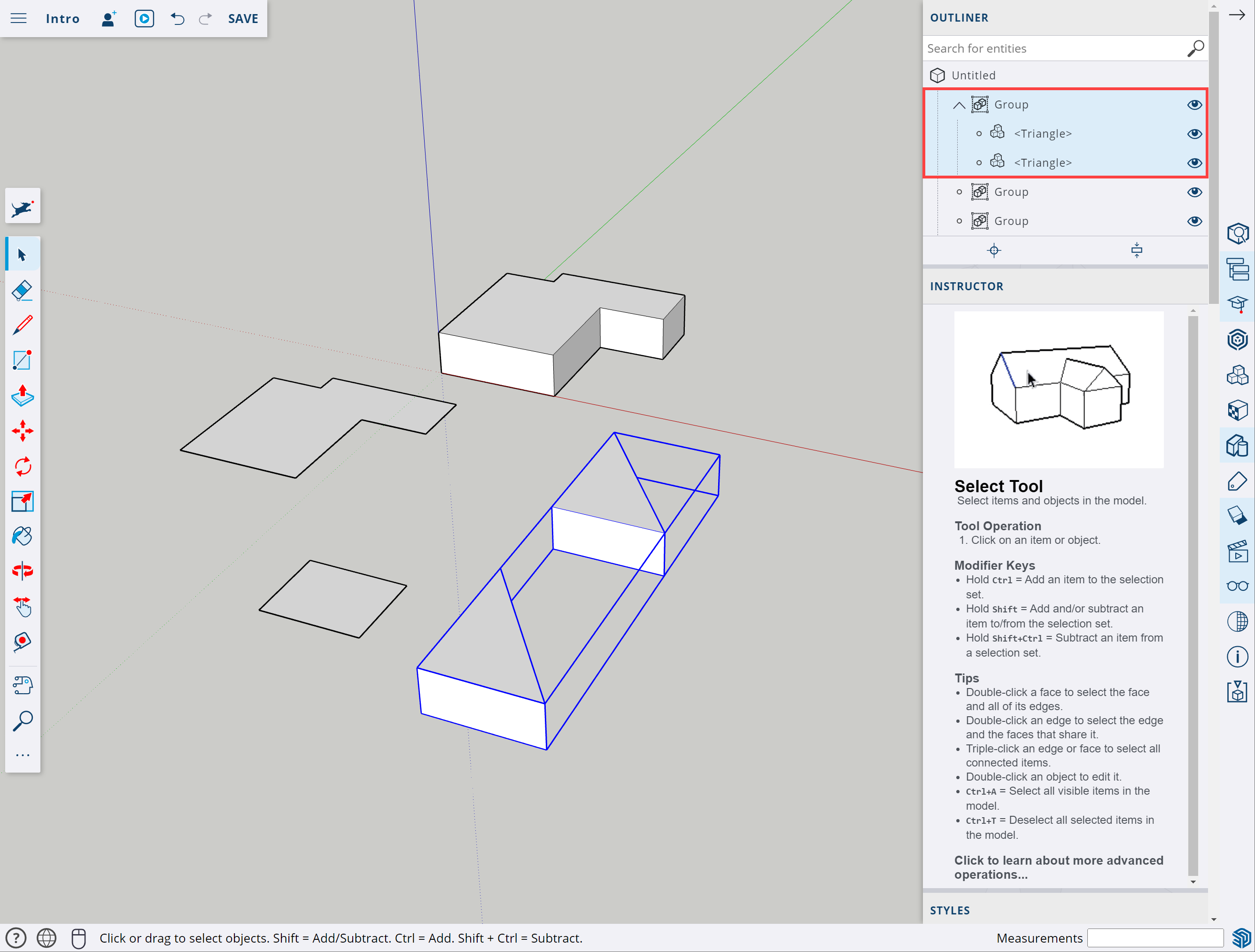
Two triangle components grouped together, as shown in the Outliner.
To edit an object in a nested group you need to double click to get into the top-level group, then double click again to get into the group or component that is in the parent group.
There is no practical limit as to how many levels deep you can go with nested groups.
Have a go! Select the two rectilinear objects in your model and make them into a group (right click and choose ‘Make Group’). You should see them intended in the Outliner under a parent group called Group.
Right click on the group in the modelling window (the main/3D window) and choose ‘Explode’. This will delete the parent group and leave the two rectilinear object groups as separate groups.
Show and hide objects
When your model starts getting large and complex, you’ll want to hide certain objects while you work and then show them again when you need them. The most common ways to hide objects are:
- In the modelling window select the objects you want to hide, right click and click on ‘Hide.’
- To unhide it, click on the dig icon in the left hand menu and type “unhide” and use one of the options.
- If you have lots of hidden objects and only want to unhide, use the ‘View Hidden Objects’ slider. This will show the hidden objects as dashed lines in the modelling window, then it is just a case of clicking on the correct one, right clicking and choosing ‘Unhide.’ Then go back to the dog icon, type ‘unhide’ and turn off the ‘View Hidden Objects’ slider.
- In the Outliner click the eye icon next to the components or groups you want to hide.
- Click the eye icon again to unhide the object.
- Use Tags.
Controlling visibility with tags
The most powerful way to show and hide objects is by using tags. Think of tags like the layers of a drawing. One sheet of paper (layer) is the base plan, another layer is the concept sketch, another layer could be used for 3D models of the buildings, another for precisely drawing the hard landscaping, and so on. In fact, tags used to be called layers in SketchUp.
To create tags click on the tag icon (looks like a price tag) in the right hand menu. Click the plus icon then give the tag a name, such as “Triangles” or “Rectilinear.”
To assign the tag to groups or components, select the object and then click the Entity Info button (the cube with magnifying glass) in the right hand menu. Click where it says “Untagged” and choose the tag you want to assign to it.
To hide all items with a given tag, click on the Tags button (the price tag icon) and then click the eye icon next to the tag you want to hide. Click it again to show those tagged objects again.
Making copies of objects
The last thing we want to talk about before we start modelling our garden and buildings is advanced ways of making copies.
If we want to make lots of copies of an object in a particular direction, we can create what is called a linear array. This is a number of copies at equal spacing along a path (line). Let’s do this together.
Activity: Copying objects using a linear array
- Start with a new SketchUp file.
- Delete the person.
- Draw a Rectangle that is 100 x 100mm.
- Use the Push/Pull tool to extrude (give it length or height) the circle to 1000mm.
- Select the object (use triple-click to select all parts).
- Make the object into a component and call it “Post 100x100x1000mm”.
- Select then move a copy of the post 5000mm backwards along the green axis.
- Use the move too again to make a copy of that new post, this time 1000mm along the red axis.
- Before you do any other action type “x5” and press Enter. This will create five copies of the post, all spaced apart by 1m (1000mm). There are six posts in total – the first one and its five copies.
- Now select the original post.
- Move a copy of this post 5000mm along the red axis and press Enter.
- Now type “/8” and press Enter to divide the 5000mm into eight even spacings between a total of nine posts.
- Use the Tape Measure to measure from the left edge of one post to the left edge of the next post. The measurement should be 625mm (5000 / 8).
Here is a short video showing these steps. Keep an eye on the numerical input box in the bottom right corner.
Now you know how to create arrays that use: a. equal spacing (the first way) and b. even distribution (the second way).
Extension activity (optional): Copying objects using a rotational array
You can also create rotational arrays. Give this a try if you want to extend yourself:
- Begin with a new file and delete the person.
- Go to plan view.
- Draw a circle (shortcut = C) at the origin that has a radius of 100mm.
- Make it into a component.
- Move it along the red axis by 1000mm.
- With the object still selected, choose the rotate tool (shortcut = Q).
- Click on the origin then move the mouse cursor along the red axis and click once.
- Move the mouse down to start to rotate the post around the origin.
- Press Ctrl to make a copy of the original post.
- Type “30” and press Enter.
- Type “x11” and press Enter.
You should have a circular array with a total of 12 posts at 30 degree spacings. Ka pai!
Like with linear arrays you can use the ‘divide by’ method to get an even distribution of your objects between the first and last point of an arc – it doesn’t need to be a full circle.
Great stuff. Now the fun can really begin!
We’re going to put all the skills we’ve just learned into practice by creating a 3D model of our sites. In the following videos we demonstrate how to make a 3D model of the rectilinear concept of the Marten Garden. The video describes the tools we used. Most of these things have already been covered, but there are a couple of new ones, which are listed below. Once you’ve watched the video you should be ready to model your own site and concept(s).
The new skills introduced in this video are:
- importing and scaling reference drawings
- using x-ray view
- working at an angle to the red and green axes
- creating hip and gable roofs
- importing 3D models, such as trees and shrubs, from the 3D Warehouse.
Drawing the ground plane
Our first task is to draw the ground plane. By ground plane we mean a flat surface that represents the building outlines and different surfaces from our base plan and the new areas from our concept plans.
Watch the following video (24:36 minutes), which shows this process for the Marten Garden.
If you are planning to take two concepts to your client, you might like to draw your base plan and then use the “Save As” command from the drop-down menu to save a new copy of this for your first concept. Then use “Save As” again to create a copy for your second concept.
Go ahead and draw the ground plane in for your site. You can choose which approach you go with, either:
- importing your reference drawings as images and rescaling them, or
- using your site survey measurements to draw it from scratch.
The first option is quicker, while the second option will produce a more accurate result.
Remember to save your work periodically.
Creating 3D buildings
One of the main purposes of creating a 3D model of the garden at the concept stage is to get a sense of what the garden rooms will feel like. To do this we need the forms of the buildings as these help define the boundaries of parts of the garden.
This video (9:52 minutes) shows how we created simple models of the Martin house and the main house.
Add simplified 3D buildings to your site, including fences if your site has any.
Creating 3D landscaping
Finally we need to add 3D elements of our hard landscaping, like new fences, gazebos, raised planters and boardwalks, as well as simple plant forms.
For the rectilinear concept for the Martin Garden the only hard landscaping we need to create in 3D is the raised planters, recessed paving, a fence and the existing deck. We then go on to add in some “low poly” (simplistic) plant forms to help understand the forms and spaces of the garden.
Watch the following video (8:53) to see how we did it. Note that parts of the video have been sped up, so the video isn’t too long.
Now create your 3D hard landscaping and then bring in models of plants from the 3D Warehouse to represent the approximate plant forms.
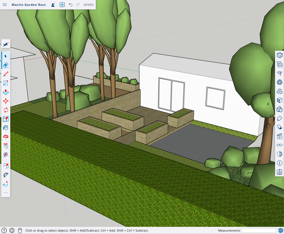
A rough concept model of the rectilinear design for the Martin Garden.
Now that you have your model, it’s time to explore!
You can use the zoom, orbit, pan tools, as you have up to this point, but SketchUp also has a set of tools specifically for exploring your model.
This video by Audrey Noakes (8:36 minutes) demonstrates these tools in SketchUp Pro (the paid version) but they are all available in SketchUp for the Web too.
Watch Sketchup: How to Navigate INTERIOR
In SketchUp for the Web, the Position Camera, Look Around, and Walk tools can be found in the large tool set (click the three dots at the bottom of the small tool set).
The Field of View command can be accessed by going to the Scenes tab in the right-hand menu and expanding the ‘Camera’ drop down. And you can create scenes from the Scenes tab by clicking the ‘+’ icon at the top and go back to any saved scene at any time by clicking on the relevant scene under ‘My Scenes.’
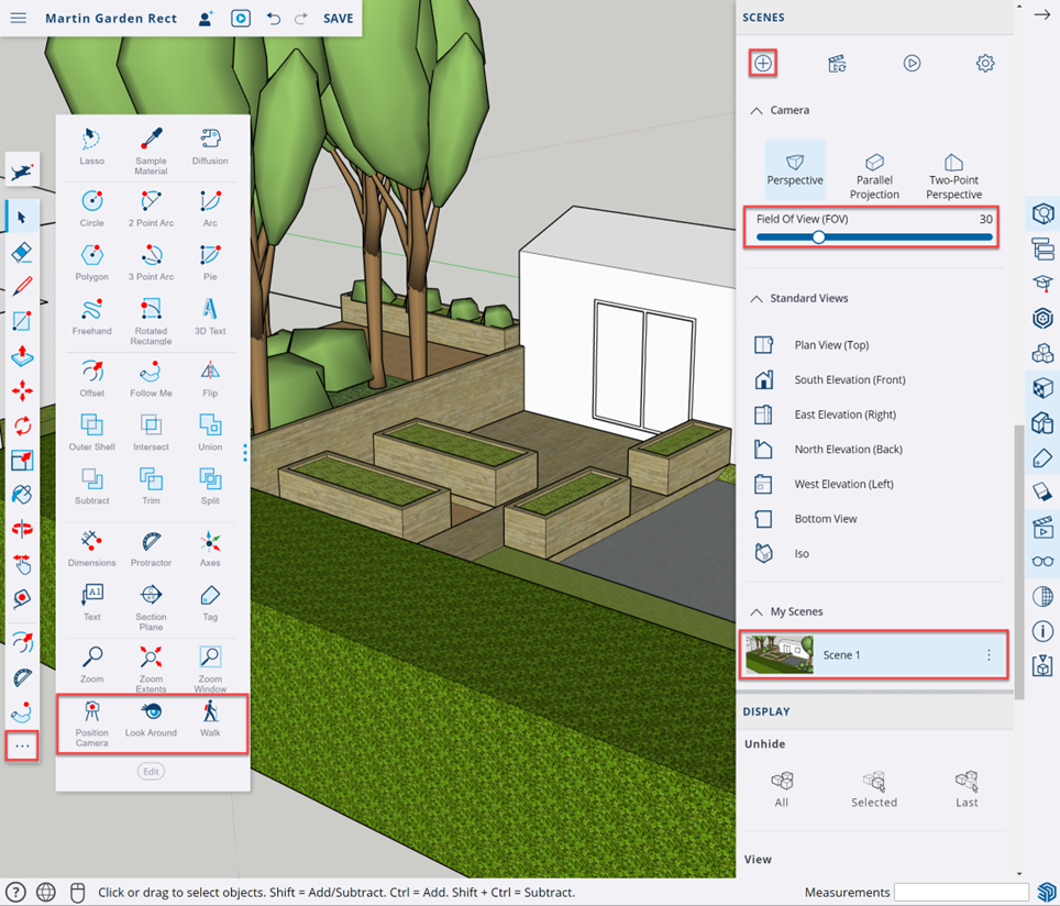
SketchUp for the Web with key exploration tools outlined in red.
Resolving the design in 3D
As you move around your 3D model, you’ll probably come across parts that you think need to be refined. Use the Tags and Outliner tabs in the right hand menu to selectively hide elements to make the model easier to work on.
Double click to enter groups or components and use the modelling tools, like the Line, Rectangle, Push/Pull tools to resolve your design.
Make it feel real
It is a good idea to add people to the model to show the scale, and to give an idea of what the different garden rooms are intended to be used for. Silhouette figures are a good option. Search the 3D Warehouse for silhouette people and add them into your scene.
Adding furniture, such as an outdoor dining suite or a BBQ, and garden equipment, like compost bins, or a shed, help show the function of key garden rooms.
These models of people and furniture are known as entourage.
The low poly plants we used earlier to create plant forms are useful, but not all that interesting to look at. You might prefer to add more realistic plants from the 3D Warehouse. Beware though, not all models are created equal.
Face camera components
When downloading models from the 3D Warehouse, keep an eye on their file size. A realistic 3D tree could be 20Mb or more. If you bring too many large models in, SketchUp will slow down and become difficult or impossible to deal with.
One option is to search for two-dimensional models. These are flat images, and most are set up as “face camera components.” This means that as you rotate around the scene they will always face you (except if viewed from above). Doing so gives the impression that the object is 3D but is a small fraction of the file size which means it won’t slow SketchUp down.
Watch: SketchUp Skill Builder: Always Face Camera
This video (2:56 minutes) by the SketchUp team shows how face camera components work and how they are created (in SketchUp Pro – it is not possible to make them in SketchUp for the Web).
When searching the 3D Warehouse use “2d” in your search, such as “2d shrub”, to look for 2D components.
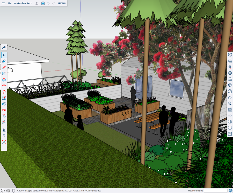
Revised model showing design revisions, such as the edge strip between the paved area and the lawn, silhouette people using the space, different plant forms and “face camera” plants, and inclusion of the catio structure.
You’ll need to decide how much time you spend adding these finishing touches.
In this topic we have:
- introduced you to SketchUp for the Web and taken you through the process of setting up a free account and logging in
- showed you how to move around in three-dimensional (3D) space in SketchUp
- covered the main 3D modelling tools needed to create a 3D model of your site.
Now it’s your turn
Revise one or two of your initial concepts using the processes talked about this and the previous topic. As mentioned earlier, for Assessment 1 you’ll need to upload photos or scans of your tracing layers so don’t throw them out.
Once you’ve done this, go ahead and complete Assessment 1: LDB03A1: Develop garden design.