Week 4
| Day One | Day Two | Day Three | Day Four | |
|---|---|---|---|---|
| Course Content | Electrical Plans – layout & location; legends; scale; symbols; specifications; load calculation; labelling etc. | Use electrical plans to prepare specifications list. Wiring Rules requirements. | LV Switching circuits – characteristics of a switch including pole and throw. | Lighting circuit switches – one-way; two-way; intermediate; double pole. |
| Self-directed Learning | Reading an electrical plan exercise. | Requirements for location & type of emergency lighting in a commercial building. | Multichoice quiz - SPST, SPDT, DPST and DPDT. | Methods to make a two-way switch connection. Truth tables. |
In order for you to gain the most value from your qualification and to prepare you for your assessment and the industry, make sure you complete all of the online and SDL tasks.

What we're covering:
- Components of an electrical plan
In the previous sessions we learnt how block diagrams, circuit diagrams, wiring diagrams and ladder diagrams all contribute to the overall electrical plan.
Let’s look at the various components of an electrical plan.
Layout and location
The plan typically includes a diagrammatic representation of the layout and location of electrical equipment, such as main and auxiliary switchboards, distribution boards, power outlets, light fittings, appliances (such as air conditioning units, hot water systems, and ranges), telephone and television outlets, and data and video outlets. The plan may also include information on the location of electrical conduit, cable trays, and other components.
The NZ Building Code requires the electrical, or energy services, plan to show the location of electrical, gas, communications, and mechanical ventilation fixtures, such as hot water supply, heat pumps, meter-boards, and smoke detectors.
Scales
As previously mentioned, scales are used to represent the physical size of the building and the location of the electrical system components in relation to each other. Electrical plans must be drawn to scale, with the scale clearly indicated on the plan. The scale should be appropriate for the size of the building or site and should allow for accurate placement of all electrical system components.
Electrical symbols
Electrical symbols are used on electrical wiring plans in order to show the location, control point(s), and type of electrical devices required at those locations. These symbols, which are drawn on top of the floor plan, show lighting outlets, power points or socket outlets, special purpose outlets, circuit breakers, fan outlets and switches. The symbols are standardised and based on the IEC standards.
Dashed lines are drawn between the symbols to denote which switches control specific lights or receptacles.
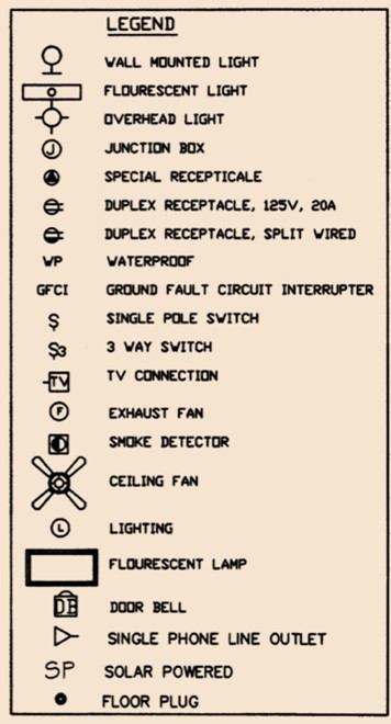
Legends
Symbols and abbreviations may vary from plan to plan which can be confusing! Legends are an essential component of electrical plans, providing key information about the symbols and abbreviations used, ensuring the plan is clear and easily understood by everyone involved.
Plan legends are typically placed near the bottom or side of the electrical plan, and they are commonly organised by the type of symbol or abbreviation. The legend must be easily readable and distinguishable from the other information on the plan.
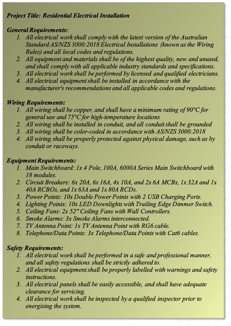
Plan Specifications
Plan specifications provide detailed information about the type of wiring, equipment ratings, installation methods, and safety requirements for the electrical work. They also provide information on any special requirements, such as energy efficiency or environmental concerns.
Plan specifications help ensure the system is installed correctly and meets all relevant codes and regulations. They are often included in the contract documents and must be followed by the installer to ensure compliance with regulations.
Exercise 20
Answer the questions on this worksheet about plans and specifications.
Load calculations
The plan may include load calculations that show the expected electrical load on the installation. Load calculations consider factors such as the type and quantity of lighting, appliances, HVAC systems, and other electrical equipment that will be used within the building.
This information is used to ensure that the installation is designed and installed correctly and can handle the maximum expected electrical load. Overloaded circuits can cause damage to electrical equipment and fires, posing a safety hazard to occupants.
Load calculations will impact on the number of circuits required for an electrical installation. The total electrical load of a building must be distributed across multiple circuits to prevent overloading, and the number of circuits required will depend on the total electrical load and the electrical code requirements. For example, if the total electrical load of a building is 100 amps, and the electrical code requires each circuit to be limited to a maximum of 20 amps, then a minimum of 5 circuits would be needed to distribute the electrical load. (Factors such as the type and number of electrical devices and building layout also impact the number of circuits required.)
Regulatory compliance
The plan may include information on regulatory compliance, such as compliance with the Wiring Rules, the Building Code, and other relevant standards and regulations.
Labelling Techniques
Labelling techniques may be included on the electrical plan to provide information about the electrical systems and devices on the electrical plans. Some of the commonly used labelling techniques are:
- Circuit Identification: Each circuit on the electrical plan is labelled with a unique identification number or letter which provides information about its specifications, such as the voltage rating, current rating, and conductor size.
- Device Identification: Each device on the electrical plan is labelled with a unique identification number or letter which identifies the device and provides information about its specifications, such as the type, rating, and location.
- Panel Schedules: Panel schedules are used to provide information about the circuit breakers and their corresponding loads. These schedules include the circuit identification, device identification, and other specifications, such as the voltage, current, and power ratings.
- Earth: As you already know, earth is a reference point in an electrical circuit used for safety purposes. Typically, a metal rod or plate buried in the earth, it is connected to the electrical system to provide a safe path for electric current in case of a fault.
Self-directed Learning
Refer to this diagram about the electrical plan to answer the questions in the worksheet you downloaded for Exercise 20.

What we're covering:
- residential floor plans
This lesson builds on the content of the previous lesson.
Exercise 21
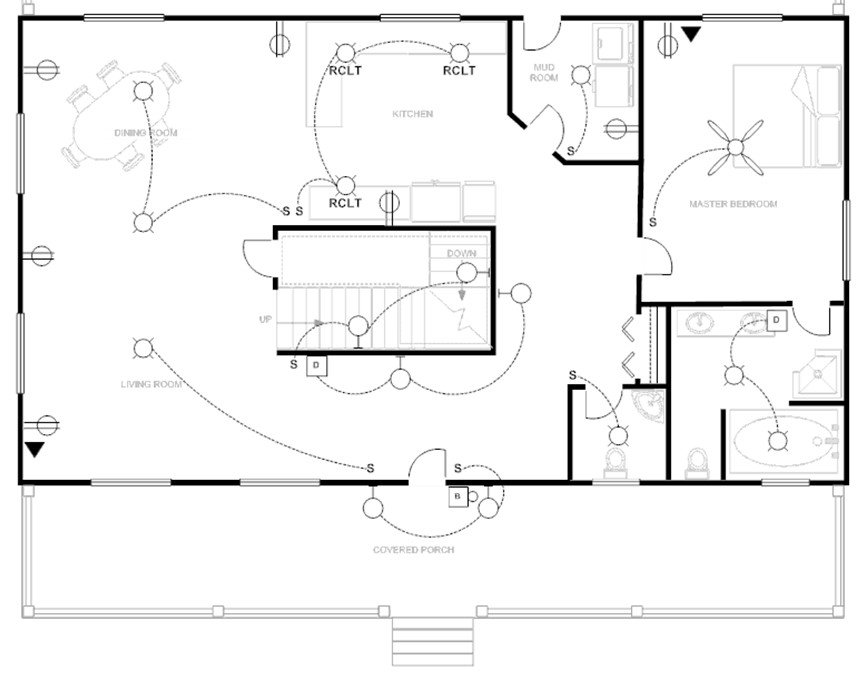
Interpret the electrical floor plan for the residential dwelling and then answer the questions here.
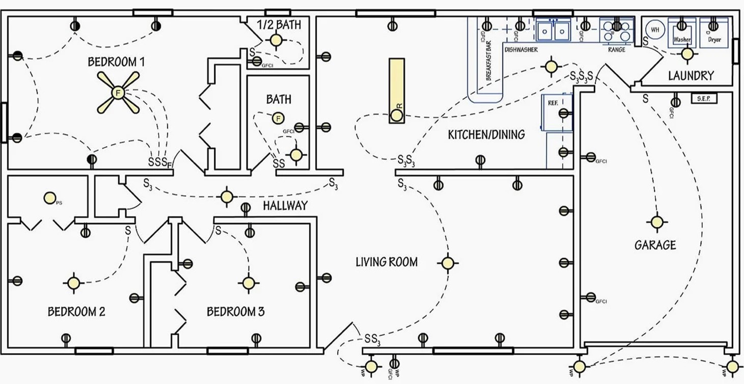
- The electrical floor plan does not include a legend. Create a legend suitable for this plan.
- Prepare a plan specification. Write your answers in the table provided. Post your table on the class forum to check whether you correctly identified all the electrical devices and their quantities.
Exercise 22
Answer the following questions regarding electrical plans. There is space for you to do this on the worksheet that you downloaded for Exercise 21. Make sure you cite any references you use to find your answers. AS/NZS3000:2018, NZECP 51:2004 etc.
- What is the minimum height that a switchboard must be installed above a floor according to?
- What are two places that switchboards are not allowed to be located?
- What is the minimum number of lighting circuits required for a domestic installation?
- Name two domestic appliances require their own circuit.
- What distance must a cable in your electrical installation be placed from a telecommunications circuit, or a circuit operating at a voltage different from 230V?
- What is the maximum number of 10A double power outlets per circuit allowed in areas other than kitchens and laundries?
- What is the maximum number of 10A double power outlets per circuit allowed in kitchens and laundries?
- What is the minimum height a socket-outlet must be installed above the floor of a bathroom or laundry?
- Which types of fixed electrical equipment in residential installations require RCD protection?
- What is the maximum rated residual current that RCDs protecting these circuits?
Self-directed Learning
Imagine you are designing the electrical plan for a commercial building. Investigate the requirements for the location and type of emergency lighting in a commercial building according to NZ regulations. Summarise your findings as bullet points on the class forum and compare to your findings to others in the group.

What we're covering:
- Low voltage switching circuit purpose
- Components
- Types of switches
- Switch characteristics
Introduction
A low voltage switching circuit is a type of electronic circuit that helps you turn on or off an electrical device or machine with a low amount of electricity. It has a switch or control device that is activated by a low voltage signal, like a small electrical pulse.
The circuit is designed to handle low voltages, which are usually less than 50 volts. It is commonly used in electronic devices and systems to control power to different parts or to turn specific functions on or off. For example, it can be used to turn on a light bulb or start a motor in a machine.

Components of a low voltage switching circuit
Some of the basic components of a low voltage switching circuit include:
- Power supply: A power supply is the source of electricity for the circuit. It can be a battery, transformer, or other device that converts electrical energy from one form to another.
- Switch: A switch is a device that controls the flow of electricity through the circuit. It can be a simple mechanical switch or an electronic switch, such as a transistor or relay.
- Load: A load is a device or component in the circuit that consumes electrical energy. It can be a light bulb, motor, or any other device that uses electricity to perform a task.
- Wiring: Wiring is the physical connection between the components in the circuit. It can be made of various materials, such as copper or aluminium, and comes in different sizes depending on the amount of current that needs to be carried.
- Control circuit: A control circuit is a circuit that controls the operation of the switching circuit. It can be a simple on/off switch or a more complex electronic circuit that uses sensors or feedback to control the switch.
- Protection devices: Protection devices, such as fuses or circuit breakers, are used to protect the circuit from overloads or short circuits that can damage the components or cause a fire hazard.
Switches
We use switches all the time without even thinking about it. From the light switches on walls, to the buttons on appliances and the touchscreens on our smartphones, switches play a fundamental role in controlling the flow of electricity and enabling us to interact with the devices we use.
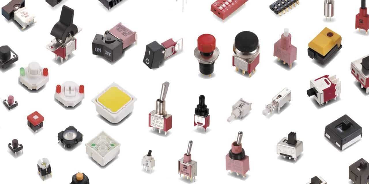
In addition to their use in consumer electronics and household appliances, switches are also critical components in many industrial and commercial applications, helping to control machines and equipment, distribute power, and automate systems.
Exercise 23
- List the different types of switches you use throughout the day.
- Do they all work the same way? What are some of the different mechanisms?
You may have mentioned some of these switches as you thought about your day:
- Light switches work by interrupting the flow of electricity to a light fixture.
- Power switches work by interrupting the flow of electrical current from the power source to the device.
- Button switches work by making or breaking a circuit when a button is pressed or released.
- Pressure switches work by sensing changes in pressure and activating or deactivating a circuit accordingly.
- Rotary switches work by rotating a knob or lever to select one of several positions, which activate different circuits or functions.
- Reed switches work by using a pair of magnetic contacts that open or close a circuit when a magnetic field is present.
- Proximity switches work by sensing the presence of an object without physical contact, using technologies such as infrared, magnetic, or capacitive sensing.
A switch is a device that controls the flow of electricity in a circuit by allowing or preventing the current from flowing through it. In other words, a switch can make or break an electrical circuit.

Switches are a crucial part of the control system in electronic devices because they enable us to turn devices on and off. Every electrical or electronic device uses at least one switch to perform the ON and OFF operation.
Characteristics of a Switch
There are two important characteristics of a switch that describe its operation: poles and throws.
Pole refers to the number of circuits that one switch can control for one operation of the switch, e.g., a single-pole switch can only control a single circuit, while a double-pole switch can control two circuits. The number of poles is usually represented by a number, such as 1P for a single-pole switch and 2P for a double-pole switch. Some switches can have even more poles, such as 3P or 4P switches.
Throw indicates the number of output connections or positions that the switch can contact. A single-throw switch has one position that it can contact, while a double-throw switch has two positions that it can connect to. The throw of a switch is represented by a number, such as 1T for a single-throw switch, 2T for a double-throw switch. Switches can have even more throws, such as 3T or 4T switches.
A pole is like a door and a throw is like the number of rooms the door can open into.
Common examples of switch types based on their poles and throws include:
- Single-pole, single-throw (SPST): This is the simplest type of switch and is used to turn a circuit on or off. A light switch is a common example of an SPST switch.

- Single-pole, double-throw (SPDT): This type of switch is used to switch between two circuits. For example, it could be used to switch between two different audio sources in a speaker system.

- Double-pole, single-throw (DPST): This type of switch controls two circuits with a single on/off switch. It is commonly used for high-voltage applications such as controlling large motors.

- Double-pole, double-throw (DPDT): This type of switch can switch between two circuits and has two on positions and two off positions. It is commonly used in electronics for switching between different inputs or outputs.

The number of poles and throws of a switch determines how many circuits it can control and how it can connect them together. Understanding the poles and throws of switches is important when selecting the appropriate switch for an installation.
SPST and SPDT Explanation
The SPST switch is the basic ON and OFF switch, consisting of one input contact and one output contact. It can switch a single circuit and either make (ON) or break (OFF) the load. The contacts on an SPST switch can be configured as either normally open or normally closed.

The SPDT switch has three terminals, with one input contact and two output contacts. This means it has two ON positions and one, OFF position. These switches are used as changeover to connect the input between two choices of outputs. The contact that is connected to the input by default is referred to as the normally closed NC contact, while the contact that will be connected during ON operation is called the normally open NO contact.
Exercise 24
On a piece of paper draw the symbols for a Double Pole Single Throw Switch (DPST) and a Double Pole Double Throw Switch (DPDT) and explain in your own words how each operates. Take it to class to show your tutor when you are next on campus.
Momentary and Latched Switches
Switches can also be classified based on their action, which is either momentary or latched. Momentary switches, like push buttons, are designed to create a temporary connection or break in a circuit, which is only maintained if the switch is being pressed or activated. Once the pressure is released, the switch returns to its original state and the circuit is broken. Momentary switches are generally activated by pressure however, they can be activated in various ways, such as through pressure, temperature, or light, making them more versatile than latched switches.
Latched switches maintain the state or position that they are set in, until they are physically changed. This means that once the switch is activated or pressed, it will stay in that position until it is physically changed to the other position. A common example of a latched switch is a light switch that you flip on and off to turn the light on or off. Once you flip the switch to the on position, it stays in that position until you flip it back to the off position. Since latched switches maintain their state until physically changed, they are less prone to accidental disconnections, providing a more reliable connection. They can be useful for applications where a certain state or setting needs to be maintained, such as locking mechanisms or power controls.
Consolidate some of this information about switches by watching the videos.
Types of switches Used for Electrical Circuit
What are the Types of Switches?
Self-directed Learning

What we're covering:
- types and configurations of lighting switches
An electric lighting circuit can be as simple as one light and one switch, but it can also be configured with multiple lights and switches. To accommodate these different configurations, manufacturers produce a variety of switch types for lighting circuits, including one-way (single pole), two-way (two pole), intermediate, and double pole.
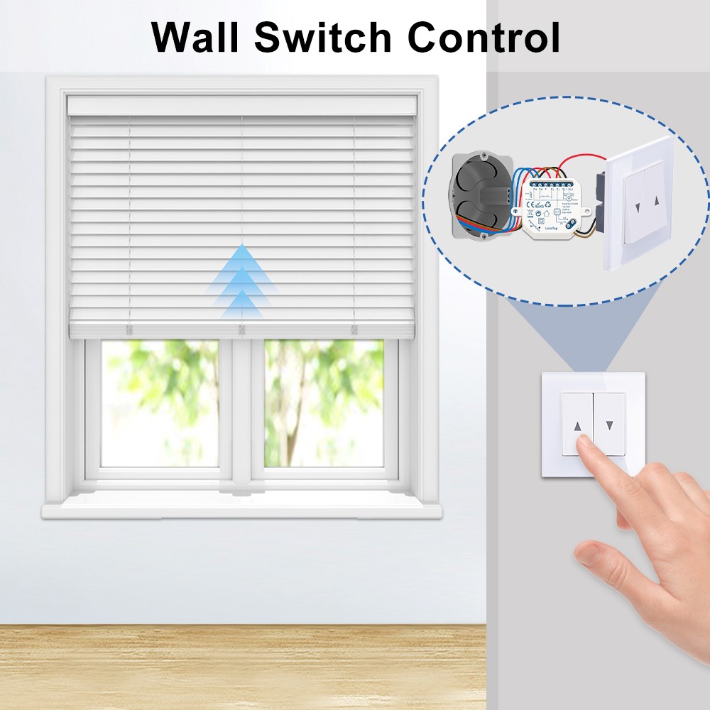
These switches can also be used in other applications where the same device needs to be controlled from multiple locations. One-way switches can be used to control fans or pumps from a single location, while two-way and intermediate switches can be used to control motorised curtains and blinds, from multiple locations.
One-way switches
A one-way light switch is a standard SPST switch. It controls the flow of electricity to a single circuit from a single location and has a simple on/off mechanism. The 'one way' switch makes contact in one position only.

Watch this video demonstrating how to wire a lighting circuit.
Basics: Wiring a Lighting Circuit
Also refer to NZECP 51:2004 (Electrical Work), Figure 3 which shows the wiring diagram for a 1-way lighting circuit.
Two-way switches
A two-way switch is like combining two, one-way switches into one.
The two-way light switch is a standard SPDT switch with three terminals. The three terminals are usually named COM, L1 and L2. In one position, the COM and L1 terminals are connected, while in the second position, the COM and L2 terminals are connected. (All three terminals of a two-way switch cannot be connected simultaneously.)

This type of connection is typically called a “break before make” design, as the first connection must be broken before making the second connection. This contrasts with a regular two terminal switch, which is just a make-or-break device.
Two-way light switches are commonly used in hallways or staircases where two switches are required to control the same light. In this case, one switch is located at the top of the stairs and the other at the bottom. When the switch at one location is flipped, the light turns on or off, and the other switch mirrors the action.
Watch the videos explaining two-way switching and how to wire a 2-way switch.
Also refer to NZECP 51:2004 (Electrical Work), Figure 4, which shows the wiring diagram for a 2-way lighting circuit where 1 light is being controlled by 2 light switches. Could you explain this drawing to someone?
Intermediate switches
An intermediate switch is a type of electrical switch used in a multi-way switching circuit, i.e., a circuit that allows you to control a single light or group of lights from multiple locations. When you have three switches controlling one light, the switch in the middle will always be an intermediate switch (and the others need to be two way).
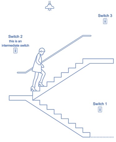
An intermediate switch, also known as a three-way switch, works as a DPDT (double-pole, double-throw) switch. The intermediate switch does not have an 'off' position and is designed with four terminals that enable the switch to connect two active wires and two load wires in different ways, depending on the position of the switch. When the switch is toggled, it alternates the supply between the two sets of wires, allowing the light or device to turn on or off from different locations. In other words, the intermediate switch acts as a bridge between the other switches in the circuit, allowing them to communicate with each other and control the light or device together.

Double pole
A double pole switch has two separate circuits that can be controlled independently with one switch. It works by having two sets of contacts that can be toggled to either connect or disconnect the circuits. When the switch is turned on, both circuits are connected, allowing electricity to flow through both. When the switch is turned off, both circuits are disconnected, breaking the flow of electricity. Double pole switches are often used to control high-power devices or appliances, such as electric water heaters or air conditioners, as they can handle higher voltage and current than a single pole switch.
A double pole single throw (DPST) switch controls two circuits (poles) and has 2 states an “on” (closed) state and an “off” (open) state. It has four terminals in total, two inputs and two outputs which are all controlled by the same switch.

A double pole double throw (DPDT) switch is connected to two different circuits, each input can be connected to either of the outputs with six terminals in total, the two inputs and 4 outputs. These types of switches have 3 states; open (off), circuit 1 closed and circuit 2 closed. There are 4 contacts in total.


Self-directed Learning
From the videos you will know there is more than one method to make a two-way switch connection. Two different methods are shown here.
Standard Two-Way Switch Wiring (3-Wire Control)

Two-Way Switch Wiring (2-Wire Control)

Find out which method is used in New Zealand and why it is preferred.