Week 3
| Day One | Day Two | Day Three | Day Four | |
|---|---|---|---|---|
| Course Content | Single-phase transformers - key components; winding configurations; designs. | Transformer selection; transformer ratings; nameplates; load capacity. | Single-phase transformer applications. Safety considerations for using isolating transformers. | Single-phase motors applications key components the stator and the rotor windings centrifugal switch bearings capacitors. |
| Self-directed Learning | Complete the set of self-check questions. | Find out how oil is used as an insulator in transformers and answer questions. | Comparison table for auto and double-wound transformers. | Complete quiz questions. Watch video about how the single-phase induction motor works. |
In order for you to gain the most value from your qualification and to prepare you for your assessment and the industry, make sure you complete all of the SDL tasks.

What we're covering:
- Single-phase transformers - key components; winding configurations; designs.
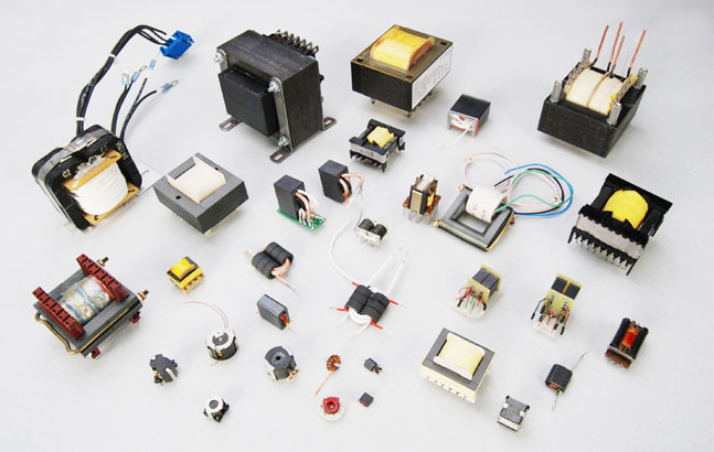
A single-phase transformer is an electrical device that transfers electrical energy between two or more windings through electromagnetic induction. It consists of a laminated core and two windings: the primary winding and the secondary winding. Single-phase transformers are designed to work with single-phase alternating current (AC) systems.
Single-phase transformers operate based on Faraday's law of induction. This law states that a changing magnetic field induces an electric current in a conductor. In a transformer, the alternating current in the primary winding generates a changing magnetic field. This field then induces an alternating current in the secondary winding. The number of turns in the windings determines the output voltage.
AS/NZS 61558.1:2018
Safety of Power Transformers, Power Supplies, Reactors and Similar Products.
AS/NZS 61558.1:2018 is a safety standard that applies to various types of dry-type transformers, power supply units (including switch mode power supply units), reactors, and their combinations. It specifically focuses on stationary or portable equipment that operates independently or in association with each other. The standard covers both encapsulated and non-encapsulated windings.
Key components of a single-phase transformer
- Core: The core is the material that the windings are wrapped around. It is typically made of laminated steel to minimise energy losses and provide a path for the magnetic flux generated by the windings.
- Primary Winding: The windings are the coils of wire that are wrapped around the core. The primary winding is connected to the input voltage source and receives the electrical power.
- Secondary Winding: The secondary winding receives the induced current from the magnetic field and delivers the transformed output voltage.
- Insulation: Insulators prevent the flow of current between the windings and the core.
- Varnish is used to protect the windings and the core from moisture and corrosion.
Step-Up and Step-Down Transformers

- A step-up transformer increases the input voltage to a higher output voltage. It has more turns in the secondary winding than in the primary winding, resulting in voltage amplification.
- Conversely, a step-down transformer decreases the input voltage to a lower output voltage. It has fewer turns in the secondary winding than in the primary winding, resulting in voltage reduction.
Winding Configurations
Different kinds of winding configurations are used in transformers to meet specific application requirements and achieve desired electrical characteristics.
Reasons for using different winding configurations include:
- Voltage Transformation: Transformers are primarily used for voltage transformation, where the primary winding is connected to the input voltage source, and the secondary winding delivers the desired output voltage. The winding configuration is selected to achieve the desired voltage transformation ratio.
- Power Transfer: Transformers are designed to efficiently transfer electrical power from the primary winding to the secondary winding. The winding configuration, such as the number of turns and their arrangement, is optimized to minimise power losses and maximize power transfer efficiency.
- Isolation and Safety: Transformers can provide electrical isolation between the input and output sides, which is crucial for safety purposes. By using separate windings or insulated sections, transformers can ensure that there is no direct electrical connection between the primary and secondary circuits, preventing the transmission of faults or voltage spikes.
- Step-Up or Step-Down Voltage: Different winding configurations allow transformers to step up or step-down voltages. For example, a transformer with more turns on the secondary winding than the primary winding will step up the voltage, while a transformer with fewer turns on the secondary winding will step down the voltage.
- Tap Selection: Transformers may have taps or additional connections along the windings to allow for voltage adjustments. This can be useful in applications where variations in input voltage or specific output voltage levels are required.
The main types of winding you will probably come across are the:
- Double Wound Transformer: A double wound transformer, also known as a two-winding transformer, is a type of transformer that has two separate windings: primary winding and secondary winding. The primary winding is connected to the input power source, while the secondary winding is connected to the load or the output. The purpose of the double winding design is to step up or step down the voltage and/or current levels according to the specific requirements of the application. It enables the efficient transfer of electrical energy from the primary side to the secondary side with a desired voltage transformation ratio.
- Auto Transformer: An auto transformer is a type of transformer that consists of a single winding that acts as both the primary and secondary winding. It has a common portion that is shared by both the input and output sides. The auto transformer is designed to provide voltage transformation by tapping different points along the winding to achieve the desired voltage ratio. Unlike the double wound transformer, the auto transformer does not provide electrical isolation between the input and output. It is commonly used in applications where a small voltage adjustment is required, such as in voltage regulation or as a voltage converter.
![]()
- Instrument Transformer: An instrument transformer is a type of transformer specifically designed for measuring and protecting electrical systems. It is used in conjunction with various instruments and devices to accurately measure high voltage and high current levels. Instrument transformers are primarily of two types:
- Current Transformers: used to step down high currents to a safe and measurable level.
- Voltage Transformers or Potential Transformers: used to step down high voltages to a safe and measurable level.
Transformer Designs
Several designs of single-phase transformers are found in electrical systems according to their intended purposes and specific voltage requirements.
- Distribution Transformers are widely used in electrical distribution networks to transfer electrical power from the transmission system to consumer premises. They typically operate at lower voltage levels and are responsible for stepping down the voltage for domestic and commercial use. Distribution transformers are found on utility poles, in substations, and various industrial settings.

- Isolation Transformers are primarily used to provide electrical isolation and safety in sensitive electronic and medical equipment. They are designed to separate the input and output circuits electrically while maintaining the same voltage level. Isolation transformers protect equipment from electrical noise, voltage spikes, and ground potential differences.
![]()
- Autotransformers as previously mentioned have a single winding that serves as both the primary and secondary winding, making them more compact and cost-effective than traditional transformers. (The "auto" in autotransformer refers to the single coil acting alone, not any automatic mechanism.) The autotransformer has electrical connection points called taps. Each tap corresponds to a different voltage, allowing a portion of the winding to act as both the primary and secondary winding. Unlike traditional transformers, autotransformers do not provide electrical isolation between the input and output circuits.

Autotransformers are commonly used for voltage conversion in appliances, lighting systems, and motors when a small voltage adjustment is needed.
- Control Transformers are used to supply power to control circuits in machinery and equipment. They provide a consistent and stable voltage output for operating control devices such as relays, contactors, timers, and solenoids. Control transformers are commonly found in industrial automation, HVAC systems, and motor control centres. A control transformer is specifically designed to step down the voltage and power the control devices of a circuit or machine. This reduced voltage creates a safer environment for technicians working on the equipment. Control transformers are typically used in electronic circuits that require constant voltage or constant current with a low power rating. Various filtering devices, like capacitors, are employed to minimise output variations and ensure a more constant voltage or current.
![]()
- Toroidal Transformers are compact and efficient transformers that use a toroidal (doughnut-shaped) core. They have improved magnetic coupling and reduced electromagnetic interference compared to traditional transformers with laminated cores. Toroidal transformers are commonly used in audio equipment, telecommunications, and renewable energy systems. A toroidal transformer has a core shaped like a donut, and both the primary and secondary windings are wound around the entire surface of the core, with insulation in between. This design helps minimise magnetic flux leakage and makes the toroidal core the preferred choice for transformer construction. Toroidal transformers offer several advantages over traditional square or rectangular transformers. They are highly efficient, operate quietly, generate minimal heat, and have a compact size. These transformers are commonly found in power supply systems, audio systems, control equipment, power inverters, and various other electronic devices. They are especially suitable for sensitive and critical electronic circuits.

Exercise 15
Test your knowledge by answering the questions on this worksheet. Take your answers to class and check with your classmates and tutor.
Self-directed Learning
Complete exercise 15

What we're covering:
- Transformer selection
- transformer ratings
- nameplates
- load capacity
Transformers are available in multiple designs, specifications, and sizes. Selecting the proper transformer for an application requires careful consideration of several factors, such as voltage, current, type of load, efficiency, environment, and cost.
Transformer ratings and load capacity are important factors to consider when selecting a transformer for a specific application.
Transformer ratings
KVA (Kilovolt-Ampere) is a measure of apparent power. It combines both the actual power used (kW) and the power needed to support certain electrical components (reactive power). In a 100% efficient system kW = kVA. However electrical systems are never 100% efficient and therefore not all of the systems apparent power is being used for useful work output.
KVA is a measure of the product of the voltage and current in the transformer.
KVA Rating for Single Phase Transformer: P = (V x I)/1000
(When applying the formula, always use voltage and current readings from the same side of the transformer.)
Transformers are usually specified in KVA or VA (Volt-Ampere) ratings, e.g., a transformer with a KVA rating of 500 can handle a maximum load of 500,000 VA or 500 kVA.
- Primary Voltage and Secondary Voltage: These values indicate the input and output voltage levels respectively, based on the transformer's turns ratio. The primary voltage is the voltage applied to the primary winding, while the secondary voltage is the voltage output from the secondary winding. Example: A transformer with a primary voltage rating of 480V and a secondary voltage rating of 240V is designed to step down the voltage from 480V to 240V.
- Current Rating: Defines the maximum current that the transformer can safely carry without exceeding its thermal limits. It is expressed in amperes (A) or kiloamperes (kA). Example: A transformer with a current rating of 1000A can handle a maximum current flow of 1000 amperes.
- Frequency Rating: Specifies the nominal frequency at which the transformer operates. The most common frequencies are 50 or 60 Hertz (Hz), depending on the region. Specialized transformers may have different frequency ratings for specific applications.
- Impedance Rating: Represents the total impedance offered by the transformer to the flow of current. It is expressed as a percentage and indicates the transformer's ability to withstand short-circuit conditions. A lower impedance rating indicates a higher short-circuit current capability.
- Efficiency Rating: Indicates the efficiency of the transformer in converting electrical power from the input side to the output side. It is expressed as a percentage and represents the ratio of output power to input power, taking into account losses in the transformer.
Nameplate Rating of a Transformer
The data on the nameplate of a transformer provides important information about its size and capabilities. It includes the transformer's rated kVA (apparent power) indicating its capacity to deliver power to the load continuously. The nameplate also specifies the voltage rating, frequency, number of phases, temperature rating, type of cooling, percentage impedance and reactance, manufacturer's name, and year of manufacture. The nameplate may have multiple voltage ratings depending on the different windings of the transformer. Always check the information on the nameplate before carrying out work involving a transformer.
Watch this video discussing transformer ratings and markings.
Exercise 16
Select the correct answer to the questions using the picture below.
Transformer load capacity
Transformer load capacity refers to the maximum voltage or current that a transformer can safely handle. It is determined by the transformer's design, including its power rating, voltage rating, and current rating. The power rating is calculated based on the temperature rise caused by losses in the transformer. Effective cooling systems can increase the load capacity.
Load capacity is typically expressed in KVA or VA and is important for selecting the right transformer. Transformers have nameplates with information about power capacity, voltage ratios, current limits, frequency compatibility, impedance, and efficiency. Different load capacities, such as 15 kVA, 30 kVA, 45 kVA, etc., are available to meet various needs. The load capacity depends on the voltage and current ratings.
Calculating the transformer load involves understanding the power requirements of appliances and choosing the appropriate transformer size. Full load represents the maximum current that can be transmitted, while the safe load is typically 75-80% of the maximum current and indicates the permissible load.
The transformer load calculation uses the output voltage and current to determine the power in kilovolt-amperes (kVA). Apparent power is calculated from the input voltage and current and then divided by 0.8 to determine the transformer's power rating.
Example
Calculate the rated power of a single-phase transformer with a load voltage of 24 V and a maximum load phase current of 5 A.
The VA rating of the transformer
= V × I
= 24 × 5
= 120 VA
Dividing the VA by 0.8, the revised VA = 150
Choose a transformer with a VA rating of approximately 150 for the load.
Exercise 17
Answer the questions on this worksheet and email your answers to your tutor.
Self-directed Learning
Carry out some research on the use of oil as an insulator in transformers and answer the following questions. Email your findings to your tutor.
- What is the role of an insulator in a transformer, and why is it necessary?
- What are the properties of oil that make it suitable for insulation?
- Are there any alternative insulating materials used in transformers? If yes, what are they, and how do they compare to oil?
- Are there any safety considerations or environmental impacts associated with the use of oil in transformers?
- Provide examples of practical applications where oil-insulated transformers are commonly used.

What we're covering:
- Single-phase transformer applications.
- Safety considerations for using isolating transformers.
Single-phase transformers are widely utilised in various electrical applications. Some of the common ways they are employed include:
- Power Distribution: Single-phase transformers play a crucial role in power distribution networks, especially in residential areas. They are used to step down the high-voltage electricity from the distribution grid to lower voltages suitable for domestic consumption (e.g., 120/240V). These transformers are typically installed on utility poles or in substations to supply power to homes, offices, and other low-voltage loads.
- Lighting Systems: Single-phase transformers are often employed in lighting systems, both indoors and outdoors. They are used to step down voltage levels for lighting fixtures such as incandescent bulbs, fluorescent lights, or LED lamps. These transformers provide the necessary voltage to ensure safe and efficient lighting operation in residential, commercial, and industrial settings.
- Appliances and Electronics: Many household appliances and electronic devices require specific voltage levels to operate correctly. Single-phase transformers are utilised to step down the voltage from the power supply to match the voltage requirements of these appliances. Common examples include transformers used in televisions, audio systems, refrigerators, air conditioners, and other household equipment.
- Control Circuits: Single-phase transformers are also utilised in control circuits, which are responsible for operating motors, relays, and other electrical components. These transformers provide the required voltage for control devices and ensure the smooth and efficient functioning of control systems in various applications, including industrial automation, HVAC systems, and motor control.
- Isolation and Safety: Single-phase transformers can be used as isolation transformers, providing electrical isolation between the power source and sensitive equipment or circuits. They help protect electronic devices from electrical noise, voltage fluctuations, and potential electrical hazards. Isolation transformers are commonly employed in medical equipment, data centres, telecommunications, and other applications where equipment safety and isolation are critical.
- Voltage Regulation: Single-phase transformers can be utilised for voltage regulation purposes. By adjusting the turns ratio of the transformer, the output voltage can be controlled within a specific range. This capability is useful in applications where voltage stability is essential, such as precision instruments, laboratory equipment, or certain industrial processes.
It's important to note that while single-phase transformers are widely used, they are generally suitable for lower power applications. For higher power requirements or three-phase systems, three-phase transformers are typically utilised.
Exercise 18
Complete the table in this worksheet with the correct letters and then write an explanation for each choice in the space provided.
Safety Considerations for Using Isolating Transformers
While isolating transformers provide electrical isolation and enhance safety, it is essential to follow specific safety precautions to ensure their proper and secure usage. The following precautions should be taken into consideration:
- Proper Installation: Isolating transformers should be installed by qualified personnel in accordance with local electrical codes and regulations. The installation must include appropriate grounding and bonding to ensure proper operation and safety.
- Adequate Sizing: The isolating transformer should be appropriately sized for the load it will be supplying. Properly matching the transformer's capacity to the load requirements ensures optimal performance and prevents overloading or underloading situations.
- Routine Inspections: Regular inspections of isolating transformers should be conducted to check for signs of damage, loose connections, or abnormal operating conditions. Any identified issues should be addressed promptly.
- Protection against Overload and Short Circuit: Isolating transformers should be equipped with appropriate protective devices such as fuses or circuit breakers to prevent overloading or short circuit conditions. These devices help safeguard the transformer and connected equipment.
- Ground Fault Protection: Ground fault protection mechanisms, such as ground fault circuit interrupters (GFCIs) or residual current devices (RCDs), should be used in conjunction with isolating transformers. These devices detect ground faults and quickly interrupt the circuit to prevent electrical shocks.
- Proper Maintenance: Regular maintenance should be performed on isolating transformers to ensure their optimal performance. This includes inspections, cleaning, and testing of insulation resistance, winding resistances, and other critical parameters as recommended by the manufacturer.
Exercise 19
Complete the matching activity below.
Self-directed Learning

What we're covering:
- Single-phase motors applications key components the stator and the rotor windings centrifugal switch bearings capacitors.
Single-phase motors are an essential component of electrical systems, powering various devices and machinery using electromagnetic principles. Unlike three-phase motors, which require a specific power supply, single-phase motors are designed to operate efficiently with a common single-phase power source found in most homes and smaller businesses.
These motors rely on a single alternating current (AC) power supply, consisting of two conductors: one active phase conductor and one neutral conductor. This single-phase power, typically obtained from the utility grid, is widely used in residential and light commercial settings.
Single-phase motors offer reliability and have low maintenance requirements, often lasting for many years. However, they require an auxiliary stator winding driven by an out-of-phase current for starting. In the case of permanent-split capacitor motors, a capacitor is connected in series with the auxiliary winding during both starting and running.
Unlike motors that create their own magnetic field, single-phase motors must be switch activated to set the rotor in motion and create a magnetic field. Once the rotor is in motion, the motor can operate efficiently.
These motors have several advantages. They are less expensive to manufacture compared to other types of motors, and they typically require minimal maintenance. In the event of repairs, they are relatively easy to service. Additionally, single-phase motors have a long lifespan, with most failures attributed to improper application rather than manufacturing defects.
Single-phase motors also have their limitations. They may occasionally run slow, overheat, or fail to start. Any electrical shock experienced while touching the motor indicates a problem that requires immediate repair.
Applications
Single-phase motors are important in various sectors and applications, including:
- Residential Applications: Single-phase motors power essential household appliances like refrigerators, air conditioners, washing machines, fans, and pumps, enhancing comfort and convenience at home.
- Commercial and Small Industrial Applications: Single-phase motors provide a cost-effective solution where three-phase power availability is limited. They drive equipment such as compressors, blowers, conveyors, pumps, and small machinery in commercial and small-scale industrial operations.
- Agricultural Sector: Single-phase motors are crucial for efficient agricultural practices, powering irrigation systems, water pumps, and farm equipment. They are particularly valuable in rural areas with limited three-phase power infrastructure.
- HVAC Systems: Heating, ventilation, and air conditioning systems in both residential and commercial buildings rely on single-phase motors to drive fans, blowers, and compressors, ensuring proper air circulation and temperature control.
- Mobility and Transportation: Single-phase motors power electric bikes, scooters, and smaller electric vehicles. Their compact size, simplicity, and adequate power output make them suitable for propulsion in compact electric vehicles.
- Renewable Energy Systems: Single-phase motors play a vital role in renewable energy systems, such as solar power systems and wind turbines. They convert generated electricity into mechanical energy, contributing to the wider adoption of clean energy solution.
Key components of single-phase motors
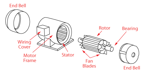
The AC motor consists of two main parts: the stator and the rotor.
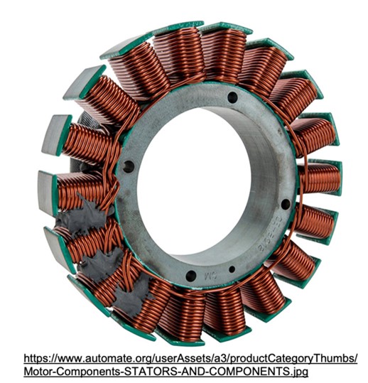
STATOR
The term ‘stator’ is derived from the word stationary; hence the stator is the stationary part of a single-phase motor responsible for generating a rotating magnetic field. It consists of laminated steel cores that provide a path for magnetic flux. The stator also houses the motor windings, which are crucial for creating the magnetic field necessary for motor operation. These windings consist of coils of wire placed in slots within the stator and connected to the power supply. By combining the laminated core and the stator windings, the stator plays a central role in the functioning of a single-phase motor.
- Definition and Function: The stator is the stationary part of an electric motor. Its primary function is to generate a magnetic field that interacts with the rotor to produce motion (in motors) or induce electrical energy conversion (in alternators and generators). The stator's magnetic field is vital for initiating and sustaining the motor's operation.
- Construction and Components: The stator is typically comprised of several key components, including:
Stator Core: The stator core is a stack of laminated iron or steel sheets forming the stationary structure of the motor. It provides support and magnetic path for the magnetic field generated by the stator windings.
Stator Windings: These are coils of wire wound around the stator core, carrying the electrical current. The arrangement and connection of the windings determine the magnetic field pattern and characteristics.
Magnetic Poles: The stator incorporates pole pieces, regions of concentrated magnetic field within the core. The number and arrangement of poles vary based on the motor design and application.
- Magnetic Field Generation: By connecting the stator windings to an electrical power supply (AC or DC depending on the motor type), an electric current will flow through the windings, resulting in the creation of a magnetic field. The specific configuration of the windings generates a magnetic field pattern necessary for motor operation.
- Pole Configuration: The stator typically has pole pieces, which are sections of the stator core where the magnetic field is concentrated. The number and arrangement of these poles depend on the motor design and application. For example, a three-phase motor may have multiple poles to create a rotating magnetic field, while a single-phase motor typically has fewer poles.
- Interaction with the Rotor: The stator's magnetic field interacts with the rotor, the rotating part of the motor. This interaction causes torque production, initiating the rotation of the rotor. The stator's magnetic field may either induce motion by attracting and repelling permanent magnets (as in brushless motors) or interact with conductive elements to create electromagnetic forces (as in induction motors).
- Heat Dissipation: The stator windings can generate heat during motor operation due to electrical resistance. To prevent overheating and ensure efficient performance, the stator is designed to dissipate heat effectively. This may include the use of cooling mechanisms like fins, ventilation, or external cooling methods.
- Stability and Support: The stator provides stability and support to the motor's internal components. It holds the rotor in place and maintains the necessary air gap between the rotor and stator. Additionally, the stator may have supporting structures to secure it within the motor housing.
ROTOR
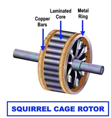
The rotor is the rotating part of a single-phase motor. It is responsible for converting the magnetic field into mechanical energy to drive the motor. Single-phase motors typically have two types of rotors: squirrel cage and wound rotor.
- Squirrel Cage Rotor: The squirrel cage rotor consists of laminated iron cores and conductive bars that are shorted at the ends by end rings. When the stator's magnetic field interacts with the rotor, currents are induced in the conductive bars, creating a magnetic field that interacts with the stator's magnetic field, resulting in rotor rotation.
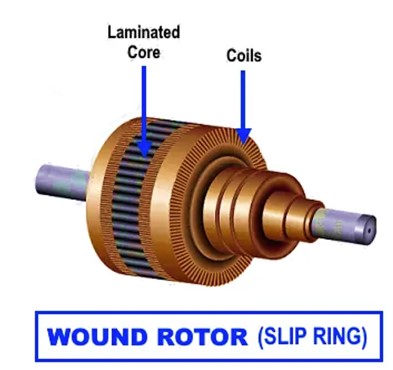
- Wound Rotor: Some single-phase motors, particularly larger ones, may have wound rotors. Wound rotors feature conductive windings that are externally connected to resistors or slip rings. These components allow for external control of rotor resistance, enabling better control over motor speed and torque.
WINDINGS, BEARINGS, AND CAPACITORS
Other important components in the single-phase motor include:
- Windings: The windings are coils of wire placed in the stator of a single-phase motor. They are responsible for creating the magnetic field necessary for motor operation. Single-phase motors typically have two main windings: the main winding and the auxiliary winding.
Main Winding: The main winding is connected directly to the power supply and provides the primary magnetic field for motor operation.
Auxiliary Winding: The auxiliary winding, also known as the starting winding, is used to provide an initial rotating magnetic field during motor start-up. It is typically higher in resistance compared to the main winding and is disconnected once the motor reaches a certain speed.
- Centrifugal switch: The centrifugal switch in single-phase motors controls the connection between the start winding and run winding. It allows the start winding and starting capacitor to be energised initially, providing additional torque to start the motor. As the motor accelerates, the centrifugal switch opens, disconnecting the start winding and capacitor, leaving only the run winding connected for normal operation. The centrifugal switch prevents the start winding from remaining energised during running, avoiding excessive current, overheating, and reduced efficiency. It protects the motor from damage and optimizes performance. Note that not all single-phase motors have a centrifugal switch; other motor types like shaded-pole and PSC motors operate differently.
- Capacitors: Capacitors play a significant role in certain types of single-phase motors. They are used to improve motor performance and efficiency, particularly during start-up and running. Capacitors provide an additional phase shift or starting torque boost, aiding in motor starting and smoother operation. Capacitors can be classified as start capacitors (used during start-up) or run capacitors (used during running).
Start Capacitors: Start capacitors are used to provide an additional phase shift and higher starting torque during motor start-up. They are typically disconnected by a centrifugal switch once the motor reaches a certain speed.
Run Capacitors: Run capacitors are connected in series with the motor winding throughout motor operation, enhancing motor performance and efficiency.
- Bearings: Bearings in single-phase motors are crucial for supporting and enabling smooth rotation of the motor's rotor. Common types of bearings used in single-phase motors include ball bearings and sleeve bearings. Ball bearings provide reduced friction and greater durability, while sleeve bearings offer simplicity and cost-effectiveness.
Exercise 20
Complete the questions on this worksheet.
Self-directed Learning
Watch this video about how the single-phase induction motor works.