Week 4
| Day One | Day Two | Day Three | Day Four | |
|---|---|---|---|---|
| Course Content | The universal motor; construction, operating principle; features; speed control; reversing capability. | Single-phase motors - synchronous or induction motors. Shaded pole & Split-phase induction motors - construction, operating principles; features & advantages; applications. | Single-phase motors - capacitor start motors, capacitor start-capacitor run motors & permanent split capacitor (PSC) motors: construction, operating principles; features & advantages; applications. | Comparison chart highlighting key similarities & differences between shaded pole, split phase, capacitor start, capacitor start/run, and PSC motors. |
| Self-directed Learning | Fleming's Left-Hand Rule – principles and applications. | Comparing shaded pole motor & split-phase induction motors. | Watch videos showing how different single phase motors work. | Continue working on comparison chart, uploading to the Group Forum once completed. |
In order for you to gain the most value from your qualification and to prepare you for your assessment and the industry, make sure you complete all of the SDL tasks.

What we're covering:
- The universal motor; construction, operating principle; features; speed control; reversing capability.
Before continuing from the previous lesson, it is useful to learn about a special motor called the Universal Motor.
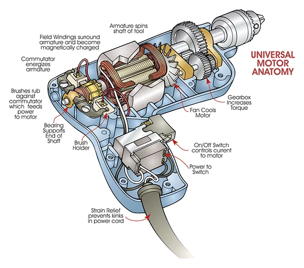
The universal motor is a special type of motor that can run on both DC and AC electrical supplies. It is named "universal" because it can work with either type of power. While three-phase motors are commonly used in industrial settings, the universal motor is designed for lower power applications and is primarily single-phase. These motors are found in small appliances like portable drills, where they are usually enclosed in a hard plastic casing.
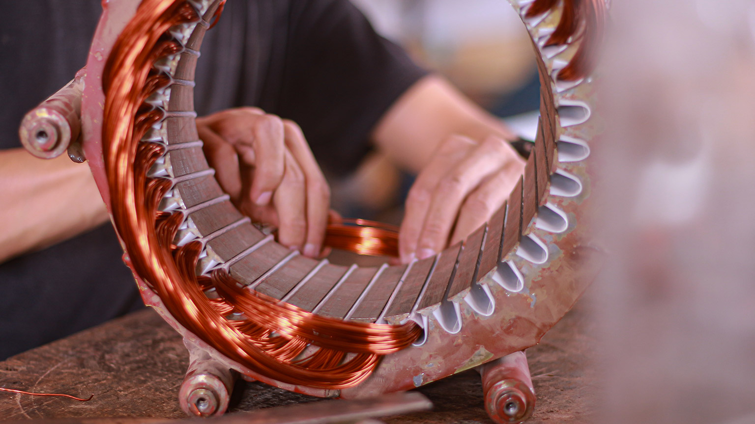
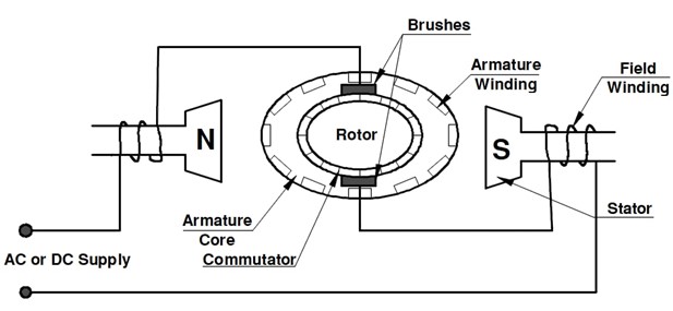
Construction
The universal motor has two main parts: the armature and the field poles. The armature is made of a layered core with slots and has a part called a commutator that connects the wires of the armature winding. Both the core and the commutator are pressed onto a metal shaft. The field poles are also made of layers of iron and have a coil of wire called the field winding wrapped around them. This design helps reduce energy losses when the motor runs on AC power.
Operating Principle
The motor works based on the interaction of magnetic fields. When DC flows through the motor, a magnetic field is created between the poles. This magnetic field interacts with the armature's field, causing the armature to spin. To understand the direction of rotation, we use Fleming's left-hand rule (see SDL), to help us figure out the movement of current-carrying conductors in a magnetic field.
When the direction of current changes, as it does in AC power, the polarity of the field and the direction of the armature's current also change. However, the interaction between the armature and the main field keeps the rotation in the same direction. To reverse the motor's direction, we need to change the polarity of the main field relative to the direction of the armature's current. This can be done by switching the connections of either the armature or the field, but reversing both connections won't change the direction of rotation.
Watch this video explaining how the universal motor works.
Features
The universal motor has certain characteristics. It provides a lot of power compared to its size, which makes it useful for many applications. However, it has a very high speed when there is no load, which can cause mechanical problems. To address this, the motor is often used with gear trains, which reduce the speed and increase the torque. The motor's performance can be understood by looking at its speed/torque graph, which shows how the speed changes with different levels of load.
Speed control
Speed control of a universal motor can be achieved through various methods. The four common methods include:
- Tapped field winding: By adjusting the strength of the motor's field, the speed can be varied. A weaker field results in a higher speed.
- Continuously rated variable resistors: This method reduces the current supply to the motor using a variable series resistor. It is commonly used in foot-controlled sewing machines. Another option is a variable resistor in parallel with the field winding, providing better starting torque and smoother control.
- Variable centrifugal governor: This method was used in older machines like food mixers and projectors. As the motor speed increases, the centrifugal governor operates electrical contacts to open and close, maintaining a constant speed. However, continuous radio and television interference may occur without proper suppression devices.
- Electronic methods: Modern speed control methods utilise semiconductor devices. By varying the current to the motor, the speed can be adjusted. This can be achieved through half-wave control using a silicon-controlled rectifier (SCR) or full-wave control using a triac. The timing of the triggering pulse to the gate of the device determines the speed.
Reversing Capability
When it comes to reversing the rotation, the universal motor's shaft direction doesn't depend on the power supply's polarity. Instead, we can change the rotation direction by switching the connections of the brushes or the field coils. Most motors have their brushes in a neutral position and can run in both directions. Some motors may have slightly skewed brushes to improve performance in one direction.
There are two common ways to reverse the universal motor. The first method uses two series field windings - one for clockwise rotation and the other for counterclockwise rotation. By switching a single switch, we can change the direction. This method works for both AC and DC. The second method uses a device called a bridge rectifier to change the direction of the motor. However, this method is only suitable for DC usage and not for universal motors.
The universal motor is well-suited for a wide range of small power portable tools and appliances. It finds application in various devices such as domestic vacuum cleaners, weed trimmers, grinding tools, sanding tools, buffing tools, polishing tools, routing tools, and more. Its capability to operate at high speeds on light loads makes it valuable in tasks that require rapid rotations. Additionally, the universal motor exhibits high torque at low speeds, enhancing its versatility. These motors are commonly employed in sewing machines, food blenders, mixers, and portable drills, benefiting from their ability to achieve speed control with ease.
Watch this video explaining how explaining how commutated DC and universal motors work.
Self-directed Learning
Fleming's Left-Hand Rule is commonly used in electric motors to understand the relationship between magnetic force, magnetic field, and current in a conductor.
Read how to apply the rule here:

- Your thumb indicates the direction of the force or thrust on the conductor.
- Your first finger points in the direction of the magnetic field.
- Your second finger is in the direction of the current.
- The directions of the magnetic force, magnetic field, and current are all perpendicular to each other.
- Remember that the magnetic field is always in the direction from North to South, and current is always in the direction of a positive terminal to a negative terminal.
Now answer the questions in this worksheet.

What we're covering:
- Single-phase motors - synchronous or induction motors.
- Shaded pole & Split-phase induction motors - construction, operating principles; features & advantages; applications.
The following flow diagram categorizes electric motors. (It does not show all of the motors available – only the more common single-phase motors we will be studying in this course.)

You can see that single-phase motors may be classified as either synchronous or induction motors. The classification depends on its operating characteristics and the design of its rotor.
- A synchronous motor is an AC motor in which the rotor rotates at the same speed as the rotating magnetic field generated by the stator. The rotor of a synchronous motor has permanent magnets or electromagnets that are magnetically aligned with the stator's magnetic field. As a result, the rotor rotates in synchronization with the changing magnetic field. Synchronous motors are known for their precise speed control, making them suitable for applications that require constant speed, such as clocks, record players, and industrial machinery with specific speed requirements.
- An induction motor is also an AC motor, but its rotor rotates at a speed slightly lower than the rotating magnetic field of the stator. Induction motors work on the principle of electromagnetic induction. When an AC voltage is applied to the stator windings, it creates a rotating magnetic field. This rotating magnetic field induces currents in the conductive rotor, generating a magnetic field in the rotor. The interaction between the rotor's magnetic field and the stator's rotating magnetic field causes the rotor to rotate. Induction motors are widely used in various applications due to their simplicity, robustness, and ability to handle varying loads.
Most single-phase motors are induction motors. They operate on the principle of electromagnetic induction, where the rotating magnetic field of the stator induces currents in the rotor, resulting in the rotation of the rotor.
Synchronous single-phase motors are less common compared to single-phase induction motors and are typically used in specialised applications where precise speed control is required, such as in certain industrial and scientific equipment.
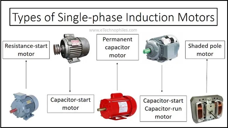
TYPES OF SINGLE-PHASE INDUCTION MOTORS
Refer back to the flowchart and you will see we will be studying five different single-phase induction motors.
SHADED POLE MOTORS
The shaded pole motor is a type of single-phase motor that offers simplicity, cost-effectiveness, and reliability for low-power applications. It operates without the need for complex windings or starters, making it a popular choice for various small-scale devices.
Construction
The construction of a shaded pole motor is relatively straightforward. It consists of the following key components:
- Stator: The stator includes the main stator winding and shading coil. The stator is typically made of magnetically conductive material, such as iron, to facilitate magnetic field transfer.
- Rotor: In shaded pole motors, the rotor is a simple squirrel cage design without any windings or additional components.
- Shading Coil: The shading coil, also known as the shading pole, is a shorted copper ring or winding placed around a portion of each stator pole. It creates a time-delayed magnetic field.
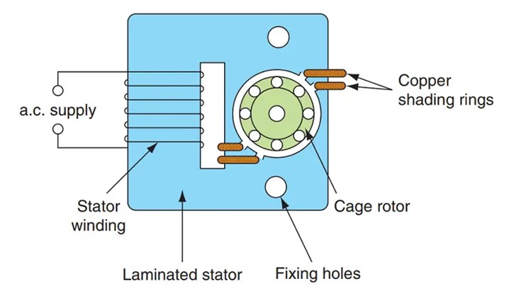
Working Principle
The operation of a shaded pole motor is based on the "shaded pole effect." When the single-phase AC current enters the C-core of the motor, it causes the main stator winding to create a pulsating magnetic field. The poles of the motor are divided into two unequal halves, with two "shading" poles created by extending the main stator winding to smaller windings on one of these halves.
As the AC current flows through the stator winding, it "shades" the winded halves by causing the magnetic field to lag through the shaded portion. This is achieved by the shading coil, which creates an opposing magnetic field, effectively slowing down the magnetic flux in the shaded area. As a result, there is an unequal distribution of inductive forces across the rotor, inducing rotation.
The C-core of the shaded pole motor, made of magnetically conductive material, plays a crucial role in transferring the pulsating magnetic field from the main stator winding to the rotor. It ensures that the shading effect takes place and facilitates the rotation of the motor.
Watch the videos showing how shaded pole motors work.
Features and Advantages
Shaded pole motors possess several notable features and advantages, including:
- Simplicity: Shaded pole motors have a straightforward construction, requiring no additional starter circuits, switches, or special windings. This simplicity contributes to their cost-effectiveness.
- Robustness: The absence of complex components like capacitors, commutators, or centrifugal switches enhances the robust nature of shaded pole motors.
- Low Starting Torque: Shaded pole motors have low starting torque, which makes them suitable for applications with low mechanical loads.
- Cost-effectiveness: Shaded pole motors are relatively inexpensive to manufacture, making them popular in small appliances and low-power applications.
Applications
Shaded pole motors find widespread use in various small-scale applications, including:
- Small Fans and Blowers: These motors are commonly found in small extractor fans, ventilation systems, and blowers for cooling and air circulation purposes.
- Appliances: Shaded pole motors power small household appliances like juice extractors, coffee grinders, electric clocks, and early tape-decks.
- Entertainment Devices: They are used in animated models, toy motors, record-player turntables, and other devices that require low starting torque.
- Disposable Motors: Shaded pole motors are often considered disposable due to their low cost, making them more economical to replace than to repair.
SPLIT PHASE MOTORS
Split-phase induction motors are a type of single-phase induction motor widely used in household appliances, small machinery, and moderate starting-torque applications. They feature a unique design with two windings, namely the main winding and the starting winding, which provide the necessary phase difference for motor rotation.
Construction
Split-phase induction motors consist of the following key components:
- Stator: The stator consists of two windings, the main winding and the starting winding. The windings are arranged in a manner that creates a time lag or phase difference of 90 degrees between the alternating currents flowing through them. The main winding has a very low resistance and a high inductive resistance, whereas the starting winding has a high resistance and low inductive resistance.

- Rotor: The rotor is a squirrel cage design, similar to other induction motors, and does not have any windings.
- Starting Mechanism: The starting winding is designed with smaller diameter wire and fewer turns compared to the main winding. This configuration provides more resistance and creates the necessary phase shift for motor starting.
Watch the video about split phase motors to gain a better understanding of how they work.
Working Principle
The operation of a split-phase induction motor is based on the interaction of the two windings and their phase difference. During motor starting, the starting winding, with its higher resistance and lower reactance, produces a phase-shifted magnetic field. This phase difference, typically around 25° to 30°, generates a rotating magnetic field that initiates motor rotation.
Once the motor reaches a percentage of full speed (around 75% of rated speed), a centrifugal switch, usually located on the output shaft, shuts off the starting winding. From that point on, the main winding, with its lower resistance and higher reactance, takes over and sustains motor operation.

Features and Limitations
Split-phase induction motors possess several features and limitations, including:
- Simple and Cost-Effective: Split-phase motors have a relatively simple design, reducing both their cost and complexity. This makes them economical and suitable for various low-to-medium starting-torque applications.
- Moderate Starting Torque: Split-phase motors provide moderate starting torque, making them ideal for applications such as fans, washing machines, oil burners, and small machine tools.
- Overheating Risk: The resistive nature of the starting mechanism in split-phase motors can lead to overheating if operated under high torque or high cycle rates. They are best suited for low torque applications to prevent coil burnout.
Applications
Split-phase induction motors find widespread use in various applications, including:
- Household Appliances: They are commonly used in household appliances like fans, refrigerators, washing machines, and small kitchen appliances.
- Small Machinery: Split-phase motors power small machinery, such as oil burners, small machine tools, pumps, and compressors.
- Moderate Starting-Torque Applications: Their moderate starting torque makes them suitable for applications where a higher starting torque is not required.
Self-directed Learning
Complete this worksheet and email your answers to your tutor.

What we're covering:
- Single-phase motors - capacitor start motors, capacitor start-capacitor run motors
- Permanent split capacitor (PSC) motors: construction, operating principles
- Features & advantages
- Applications
Capacitor starter motors
If a load requires a starting torque beyond the capability of a split-phase motor, a capacitor-start motor can be used. Capacitor start motors are a type of single-phase induction motor that use capacitors and auxiliary windings to initiate rotation. These motors do not require extra starter circuits or switches, and they employ capacitance instead of resistance to create the necessary phase difference for starting.
Construction and Features
Capacitor start motors consist of a start winding and a capacitor connected in series with it. The start winding is designed with more turns of finer wire compared to the run winding. This configuration allows for increased starting torque and smoother operation during motor start up.
Working Principle

- Starting Phase: When power is supplied to a capacitor-start motor, the start winding, and the main winding are energised. The start winding, along with the capacitor connected in series, creates a phase shift between the currents in the two windings, providing the necessary starting torque.
- Centrifugal Switch Activation: As the motor accelerates, a centrifugal switch located on the output shaft detects the motor's speed. Once the motor reaches a certain speed (around 75-80% of rated speed), the centrifugal switch opens the circuit to the start winding and the capacitor.
- Start Winding Deactivation: When the centrifugal switch opens, the start winding and the capacitor are disconnected from the circuit. The motor continues to run with only the main winding active.
- Main Winding Operation: With the start winding deactivated, the main winding generates the rotating magnetic field required for motor operation.
- Continuous Rotation: The capacitor-start motor continues to accelerate until it reaches its normal operating speed. It runs as a single-phase induction motor with only the main winding active.
- Reversing Capability: Capacitor start motors can be reversed by reversing the connections to either the start winding or the run winding, but not both simultaneously. This capability is achieved using an external reversing switch
Applications
Capacitor start motors find extensive use in various industrial applications that demand higher starting torque. They are well-suited for belt-driven conveyors, large blowers, geared applications, and other general-purpose industrial motor applications. Additionally, they are commonly employed in larger appliances like air conditioners, refrigerators, and pumps.
Advantages and Disadvantages
Compared to other single-phase motor types, capacitor start motors offer improved starting torque and the ability to handle high cycle rates. However, one drawback is their higher cost relative to split-phase motors. Despite this, capacitor start motors are valued for their reliable and efficient performance in applications that require higher starting torque.
Reversing Capability
Capacitor start motors can be reversed by reversing the connections to either the start or run winding, but not both. This reversal can be achieved by using an external reversing switch. The ability to reverse the motor adds flexibility to its application in various scenarios.
Exercise 21
Complete the questions on this worksheet and email the answers to your tutor.
Capacitor start-capacitor run motors
Construction and Features
Capacitor start-capacitor run motors consist of a start winding and a main winding. They are equipped with two capacitors, a start capacitor, and a run capacitor. During start-up, the start capacitor provides a phase shift to facilitate motor starting. These motors feature a centrifugal switch that disconnects the start capacitor once the motor reaches approximately 75% of its rated speed.
The combination of the capacitors creates a phase angle of around 90 degrees, enabling the motor to generate high starting torque. Capacitor start-capacitor run motors are designed with compact size and robust construction to ensure reliable operation. In some cases, external start-winding relays may be used for added safety or to achieve more compact motor designs.

Operating Principle
- Starting Phase: During the starting phase, both the start winding, and the main winding are energised. The start capacitor, along with the start winding, creates a phase difference between the currents, resulting in high starting torque.
- Boosted Start-Up: The start capacitor enhances the motor's start-up performance by aiding rapid acceleration and facilitating the motor to reach its rated speed quickly.
- Run Capacitor Activation: Once the motor reaches its rated speed, a centrifugal switch or potential relay activates the run capacitor. The run capacitor remains connected in parallel with the start capacitor to maintain the desired phase shift during continuous motor operation.
- Continued Operation: With both the start and run capacitors in place, the motor functions as a single-phase induction motor. The combined capacitance of the capacitors ensures efficient operation, improved torque characteristics, and reliable performance.
- Reversing Capability: Similar to other single-phase motors, reversing the direction of a capacitor start-capacitor run motor can be achieved by swapping the connections to either the start winding or the main winding, but not both simultaneously.
Applications
Capacitor start-capacitor run motors are well-suited for a wide range of applications, including:
- Air Compressors: These motors provide the necessary starting torque to drive air compressors efficiently.
- High-Pressure Pumps: CSCR motors are commonly used in high-pressure pump applications, such as water supply systems or industrial processes.
- Vacuum Pumps: They are suitable for powering vacuum pumps, delivering the required starting torque for effective suction.
- 1-10HP Applications: CSCR motors are often found in equipment requiring motor power in the range of 1 to 10 horsepower.
- Industrial Equipment: They are utilised in industrial applications that demand high starting torque and reliable operation, such as conveyor systems, blowers, and geared equipment.
Advantages
- High Starting Torque: Making them suitable for equipment with demanding start-up requirements.
- Efficient Operation: The phase shift introduced by the capacitors ensures efficient motor operation and improved torque characteristics.
- Reliable Performance: These motors are known for their reliability due to their simplistic design and ability to handle moderate-to-high starting torque.
- Reversing Capability: Similar to other single-phase motors, CSCR motors can be easily reversed by swapping the connections to the windings.
- Wide Range of Applications: From industrial equipment to hospital appliances, where high starting torque and quiet operation are essential.
Permanent split motors
Permanent Split Capacitor (PSC) motors, also known as Capacitor Run motors, are a popular type of single-phase induction motor utilised in a wide range of applications. These motors are characterized by the inclusion of a permanent capacitor that remains connected in series with the starting winding, eliminating the requirement for a centrifugal switch. PSC motors are commonly found in HVAC systems, pumps, and blowers, where they exhibit enhanced motor performance and efficiency due to the presence of a run capacitor connected in series with the main winding throughout operation.
Construction
PSC motors are constructed with two windings: the main winding and the auxiliary or starting winding. These windings are designed to have identical resistance and number of turns, ensuring balanced operation. The auxiliary winding is connected in series with a permanent capacitor, forming a continuous circuit. This eliminates the need for a centrifugal switch typically found in other motor types. The inclusion of a permanent capacitor in the series configuration allows the motor to operate seamlessly without the need for manual switching or additional control mechanisms.

Operating Principle
When power is supplied to the motor, the run capacitor and the main winding create a phase shift in the single-phase input. This phase shift produces a rotating magnetic field, allowing the motor to start and run smoothly. The capacitor's size is selected to provide optimum performance and torque at full speed.
Features
- Simplified Circuit: PSC motors eliminate the need for a centrifugal switch due to the permanent connection of the capacitor and windings. The absence of a centrifugal switch enhances reliability and reduces potential maintenance issues.
- Solid-Dielectric Capacitor: PSC motors use a solid-dielectric capacitor, capable of continuous operation in an AC circuit. The capacitor remains in series with the auxiliary winding throughout motor operation.
- Smoother Operation: The capacitor size is selected to provide a more constant strength stator magnetic field while running on load. This results in smoother operation without the characteristic pulsating hum or noise found in other motor types.
- Motor Reversal: PSC motors allow for easy motor reversal by shifting the capacitor from one winding to the other using a reversing switch. This changes the direction of rotation of the stator field, thereby reversing the motor's direction.
- Optimum Performance and Torque: The capacitor size in PSC motors is chosen for optimum performance and torque at full speed. Unlike other motor types, where high starting torque is prioritized, PSC motors sacrifice starting torque for applications with low start torque but increasing load torque with speed.
Applications
PSC motors are well-suited for low-torque applications that require instant reversing, making them ideal for applications like garage doors, gate openers, and fans. They excel in constant-speed operations where high torques are not necessary. Commonly found in HVAC systems, pumps, blowers, and various other applications, PSC motors offer better running torque, higher efficiency, and smoother operation compared to other single-phase motors. Their speed/torque characteristics make them particularly suitable for extract and intake fans, blowers, and similar loads.
Advantages
PSC motors offer simplicity, reliability, high efficiency, and relatively silent running. The absence of a centrifugal switch simplifies the motor's circuitry, making it more reliable. The solid-dielectric capacitor ensures continuous operation, and the smoother running reduces noise and vibration.
Limitations
PSC motors have low starting torque, making them unsuitable for applications with high torque requirements. They are optimized for constant-speed, low-torque applications.
Exercise 22
Complete the questions on this worksheet and email the answers to your tutor.
Self-directed Learning
Watch these videos showing how different single phase motors work.

What we're covering:
- Comparison chart highlighting key similarities & differences between shaded pole, split phase, capacitor start, capacitor start/run, and PSC motors.
This session is an opportunity to consolidate all the information from the previous sessions on single-phase induction motors.
Exercise 23
Create a comparison chart to highlight the key differences and similarities between shaded pole, split phase, capacitor start, capacitor start/run, and PSC motors.
Include information such as starting torque, efficiency, reliability, cost, speed control methods, starting mechanisms, applications, compactness and portability, noise level, lifespan or durability, special features, advantages and disadvantages etc.
Your comparison chart should include a minimum of six categories. You may include photos/diagrams, but these are not considered to be 'categories.'
You may choose any format to present your comparison chart, however you must be able to upload it to the Group Forum once completed for feedback from other class members and your tutor.
Self-directed Learning
Continue working on your comparison chart. Upload to the Group Forum once completed.