What we're covering:
- Single-phase transformer applications.
- Safety considerations for using isolating transformers.
Single-phase transformers are widely utilised in various electrical applications. Some of the common ways they are employed include:
- Power Distribution: Single-phase transformers play a crucial role in power distribution networks, especially in residential areas. They are used to step down the high-voltage electricity from the distribution grid to lower voltages suitable for domestic consumption (e.g., 120/240V). These transformers are typically installed on utility poles or in substations to supply power to homes, offices, and other low-voltage loads.
- Lighting Systems: Single-phase transformers are often employed in lighting systems, both indoors and outdoors. They are used to step down voltage levels for lighting fixtures such as incandescent bulbs, fluorescent lights, or LED lamps. These transformers provide the necessary voltage to ensure safe and efficient lighting operation in residential, commercial, and industrial settings.
- Appliances and Electronics: Many household appliances and electronic devices require specific voltage levels to operate correctly. Single-phase transformers are utilised to step down the voltage from the power supply to match the voltage requirements of these appliances. Common examples include transformers used in televisions, audio systems, refrigerators, air conditioners, and other household equipment.
- Control Circuits: Single-phase transformers are also utilised in control circuits, which are responsible for operating motors, relays, and other electrical components. These transformers provide the required voltage for control devices and ensure the smooth and efficient functioning of control systems in various applications, including industrial automation, HVAC systems, and motor control.
- Isolation and Safety: Single-phase transformers can be used as isolation transformers, providing electrical isolation between the power source and sensitive equipment or circuits. They help protect electronic devices from electrical noise, voltage fluctuations, and potential electrical hazards. Isolation transformers are commonly employed in medical equipment, data centres, telecommunications, and other applications where equipment safety and isolation are critical.
- Voltage Regulation: Single-phase transformers can be utilised for voltage regulation purposes. By adjusting the turns ratio of the transformer, the output voltage can be controlled within a specific range. This capability is useful in applications where voltage stability is essential, such as precision instruments, laboratory equipment, or certain industrial processes.
It's important to note that while single-phase transformers are widely used, they are generally suitable for lower power applications. For higher power requirements or three-phase systems, three-phase transformers are typically utilised.
Activity
Complete the table in this worksheet with the correct letters and then write an explanation for each choice in the space provided.
Safety Considerations for Using Isolating Transformers
While isolating transformers provide electrical isolation and enhance safety, it is essential to follow specific safety precautions to ensure their proper and secure usage. The following precautions should be taken into consideration:
- Proper Installation: Isolating transformers should be installed by qualified personnel in accordance with local electrical codes and regulations. The installation must include appropriate grounding and bonding to ensure proper operation and safety.
- Adequate Sizing: The isolating transformer should be appropriately sized for the load it will be supplying. Properly matching the transformer's capacity to the load requirements ensures optimal performance and prevents overloading or underloading situations.
- Routine Inspections: Regular inspections of isolating transformers should be conducted to check for signs of damage, loose connections, or abnormal operating conditions. Any identified issues should be addressed promptly.
- Protection against Overload and Short Circuit: Isolating transformers should be equipped with appropriate protective devices such as fuses or circuit breakers to prevent overloading or short circuit conditions. These devices help safeguard the transformer and connected equipment.
- Ground Fault Protection: Ground fault protection mechanisms, such as ground fault circuit interrupters (GFCIs) or residual current devices (RCDs), should be used in conjunction with isolating transformers. These devices detect ground faults and quickly interrupt the circuit to prevent electrical shocks.
- Proper Maintenance: Regular maintenance should be performed on isolating transformers to ensure their optimal performance. This includes inspections, cleaning, and testing of insulation resistance, winding resistances, and other critical parameters as recommended by the manufacturer.
Activity
Complete the matching activity below.

What we're covering:
- Single-phase motors applications key components the stator and the rotor windings centrifugal switch bearings capacitors.
Single-phase motors are an essential component of electrical systems, powering various devices and machinery using electromagnetic principles. Unlike three-phase motors, which require a specific power supply, single-phase motors are designed to operate efficiently with a common single-phase power source found in most homes and smaller businesses.
These motors rely on a single alternating current (AC) power supply, consisting of two conductors: one active phase conductor and one neutral conductor. This single-phase power, typically obtained from the utility grid, is widely used in residential and light commercial settings.
Single-phase motors offer reliability and have low maintenance requirements, often lasting for many years. However, they require an auxiliary stator winding driven by an out-of-phase current for starting. In the case of permanent-split capacitor motors, a capacitor is connected in series with the auxiliary winding during both starting and running.
Unlike motors that create their own magnetic field, single-phase motors must be switch activated to set the rotor in motion and create a magnetic field. Once the rotor is in motion, the motor can operate efficiently.
These motors have several advantages. They are less expensive to manufacture compared to other types of motors, and they typically require minimal maintenance. In the event of repairs, they are relatively easy to service. Additionally, single-phase motors have a long lifespan, with most failures attributed to improper application rather than manufacturing defects.
Single-phase motors also have their limitations. They may occasionally run slow, overheat, or fail to start. Any electrical shock experienced while touching the motor indicates a problem that requires immediate repair.
Applications
Single-phase motors are important in various sectors and applications, including:
- Residential Applications: Single-phase motors power essential household appliances like refrigerators, air conditioners, washing machines, fans, and pumps, enhancing comfort and convenience at home.
- Commercial and Small Industrial Applications: Single-phase motors provide a cost-effective solution where three-phase power availability is limited. They drive equipment such as compressors, blowers, conveyors, pumps, and small machinery in commercial and small-scale industrial operations.
- Agricultural Sector: Single-phase motors are crucial for efficient agricultural practices, powering irrigation systems, water pumps, and farm equipment. They are particularly valuable in rural areas with limited three-phase power infrastructure.
- HVAC Systems: Heating, ventilation, and air conditioning systems in both residential and commercial buildings rely on single-phase motors to drive fans, blowers, and compressors, ensuring proper air circulation and temperature control.
- Mobility and Transportation: Single-phase motors power electric bikes, scooters, and smaller electric vehicles. Their compact size, simplicity, and adequate power output make them suitable for propulsion in compact electric vehicles.
- Renewable Energy Systems: Single-phase motors play a vital role in renewable energy systems, such as solar power systems and wind turbines. They convert generated electricity into mechanical energy, contributing to the wider adoption of clean energy solution.
Key components of single-phase motors
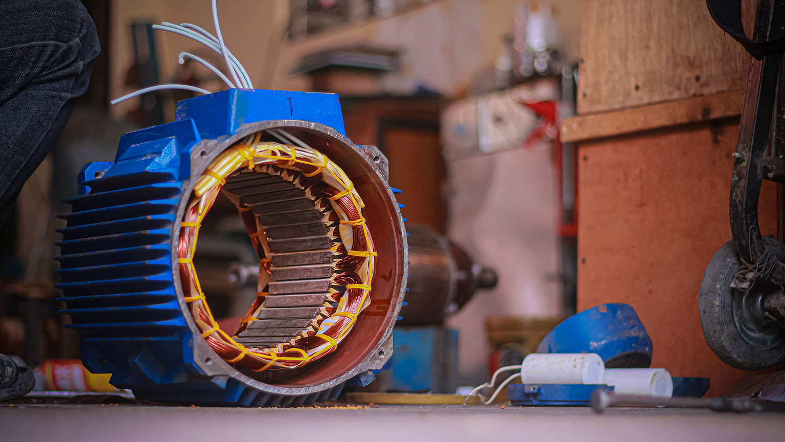
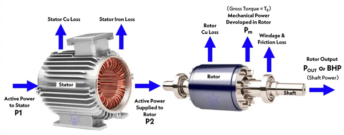
The AC motor consists of two main parts: the stator and the rotor.
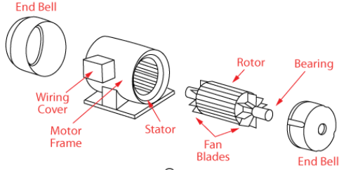
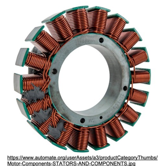
STATOR
The term ‘stator’ is derived from the word stationary; hence the stator is the stationary part of a single-phase motor responsible for generating a rotating magnetic field. It consists of laminated steel cores that provide a path for magnetic flux. The stator also houses the motor windings, which are crucial for creating the magnetic field necessary for motor operation. These windings consist of coils of wire placed in slots within the stator and connected to the power supply. By combining the laminated core and the stator windings, the stator plays a central role in the functioning of a single-phase motor.
- Definition and Function: The stator is the stationary part of an electric motor. Its primary function is to generate a magnetic field that interacts with the rotor to produce motion (in motors) or induce electrical energy conversion (in alternators and generators). The stator's magnetic field is vital for initiating and sustaining the motor's operation.
- Construction and Components: The stator is typically comprised of several key components, including:
Stator Core: The stator core is a stack of laminated iron or steel sheets forming the stationary structure of the motor. It provides support and magnetic path for the magnetic field generated by the stator windings.
Stator Windings: These are coils of wire wound around the stator core, carrying the electrical current. The arrangement and connection of the windings determine the magnetic field pattern and characteristics.
Magnetic Poles: The stator incorporates pole pieces, regions of concentrated magnetic field within the core. The number and arrangement of poles vary based on the motor design and application.
- Magnetic Field Generation: By connecting the stator windings to an electrical power supply (AC or DC depending on the motor type), an electric current will flow through the windings, resulting in the creation of a magnetic field. The specific configuration of the windings generates a magnetic field pattern necessary for motor operation.
- Pole Configuration: The stator typically has pole pieces, which are sections of the stator core where the magnetic field is concentrated. The number and arrangement of these poles depend on the motor design and application. For example, a three-phase motor may have multiple poles to create a rotating magnetic field, while a single-phase motor typically has fewer poles.
- Interaction with the Rotor: The stator's magnetic field interacts with the rotor, the rotating part of the motor. This interaction causes torque production, initiating the rotation of the rotor. The stator's magnetic field may either induce motion by attracting and repelling permanent magnets (as in brushless motors) or interact with conductive elements to create electromagnetic forces (as in induction motors).
- Heat Dissipation: The stator windings can generate heat during motor operation due to electrical resistance. To prevent overheating and ensure efficient performance, the stator is designed to dissipate heat effectively. This may include the use of cooling mechanisms like fins, ventilation, or external cooling methods.
- Stability and Support: The stator provides stability and support to the motor's internal components. It holds the rotor in place and maintains the necessary air gap between the rotor and stator. Additionally, the stator may have supporting structures to secure it within the motor housing.
ROTOR
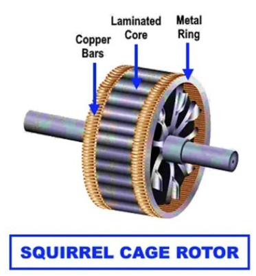
The rotor is the rotating part of a single-phase motor. It is responsible for converting the magnetic field into mechanical energy to drive the motor. Single-phase motors typically have two types of rotors: squirrel cage and wound rotor.
- Squirrel Cage Rotor: The squirrel cage rotor consists of laminated iron cores and conductive bars that are shorted at the ends by end rings. When the stator's magnetic field interacts with the rotor, currents are induced in the conductive bars, creating a magnetic field that interacts with the stator's magnetic field, resulting in rotor rotation.
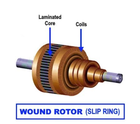
- Wound Rotor: Some single-phase motors, particularly larger ones, may have wound rotors. Wound rotors feature conductive windings that are externally connected to resistors or slip rings. These components allow for external control of rotor resistance, enabling better control over motor speed and torque.
WINDINGS, BEARINGS, AND CAPACITORS
Other important components in the single-phase motor include:
- Windings: The windings are coils of wire placed in the stator of a single-phase motor. They are responsible for creating the magnetic field necessary for motor operation. Single-phase motors typically have two main windings: the main winding and the auxiliary winding.
Main Winding: The main winding is connected directly to the power supply and provides the primary magnetic field for motor operation.
Auxiliary Winding: The auxiliary winding, also known as the starting winding, is used to provide an initial rotating magnetic field during motor start-up. It is typically higher in resistance compared to the main winding and is disconnected once the motor reaches a certain speed.
- Centrifugal switch: The centrifugal switch in single-phase motors controls the connection between the start winding and run winding. It allows the start winding and starting capacitor to be energised initially, providing additional torque to start the motor. As the motor accelerates, the centrifugal switch opens, disconnecting the start winding and capacitor, leaving only the run winding connected for normal operation. The centrifugal switch prevents the start winding from remaining energised during running, avoiding excessive current, overheating, and reduced efficiency. It protects the motor from damage and optimizes performance. Note that not all single-phase motors have a centrifugal switch; other motor types like shaded-pole and PSC motors operate differently.
- Capacitors: Capacitors play a significant role in certain types of single-phase motors. They are used to improve motor performance and efficiency, particularly during start-up and running. Capacitors provide an additional phase shift or starting torque boost, aiding in motor starting and smoother operation. Capacitors can be classified as start capacitors (used during start-up) or run capacitors (used during running).
Start Capacitors: Start capacitors are used to provide an additional phase shift and higher starting torque during motor start-up. They are typically disconnected by a centrifugal switch once the motor reaches a certain speed.
Run Capacitors: Run capacitors are connected in series with the motor winding throughout motor operation, enhancing motor performance and efficiency.
- Bearings: Bearings in single-phase motors are crucial for supporting and enabling smooth rotation of the motor's rotor. Common types of bearings used in single-phase motors include ball bearings and sleeve bearings. Ball bearings provide reduced friction and greater durability, while sleeve bearings offer simplicity and cost-effectiveness.
Activity
Complete the questions on this worksheet.
Activity
Watch this video about how the single-phase induction motor works.

What we're covering:
- The universal motor; construction, operating principle; features; speed control; reversing capability.
Before continuing from the previous lesson, it is useful to learn about a special motor called the Universal Motor.
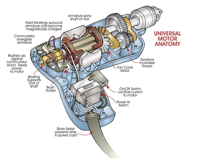
The universal motor is a special type of motor that can run on both DC and AC electrical supplies. It is named "universal" because it can work with either type of power. While three-phase motors are commonly used in industrial settings, the universal motor is designed for lower power applications and is primarily single-phase. These motors are found in small appliances like portable drills, where they are usually enclosed in a hard plastic casing.
Construction
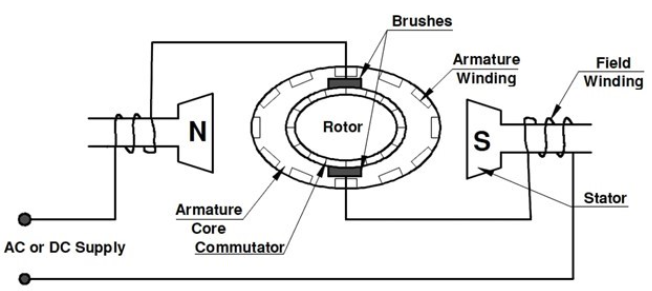
The universal motor has two main parts: the armature and the field poles. The armature is made of a layered core with slots and has a part called a commutator that connects the wires of the armature winding. Both the core and the commutator are pressed onto a metal shaft. The field poles are also made of layers of iron and have a coil of wire called the field winding wrapped around them. This design helps reduce energy losses when the motor runs on AC power.
Operating Principle
The motor works based on the interaction of magnetic fields. When DC flows through the motor, a magnetic field is created between the poles. This magnetic field interacts with the armature's field, causing the armature to spin. To understand the direction of rotation, we use Fleming's left-hand rule (see SDL), to help us figure out the movement of current-carrying conductors in a magnetic field.
When the direction of current changes, as it does in AC power, the polarity of the field and the direction of the armature's current also change. However, the interaction between the armature and the main field keeps the rotation in the same direction. To reverse the motor's direction, we need to change the polarity of the main field relative to the direction of the armature's current. This can be done by switching the connections of either the armature or the field, but reversing both connections won't change the direction of rotation.
Watch this video explaining how the universal motor works.
Features
The universal motor has certain characteristics. It provides a lot of power compared to its size, which makes it useful for many applications. However, it has a very high speed when there is no load, which can cause mechanical problems. To address this, the motor is often used with gear trains, which reduce the speed and increase the torque. The motor's performance can be understood by looking at its speed/torque graph, which shows how the speed changes with different levels of load.
Speed control
Speed control of a universal motor can be achieved through various methods. The four common methods include:
- Tapped field winding: By adjusting the strength of the motor's field, the speed can be varied. A weaker field results in a higher speed.
- Continuously rated variable resistors: This method reduces the current supply to the motor using a variable series resistor. It is commonly used in foot-controlled sewing machines. Another option is a variable resistor in parallel with the field winding, providing better starting torque and smoother control.
- Variable centrifugal governor: This method was used in older machines like food mixers and projectors. As the motor speed increases, the centrifugal governor operates electrical contacts to open and close, maintaining a constant speed. However, continuous radio and television interference may occur without proper suppression devices.
- Electronic methods: Modern speed control methods utilise semiconductor devices. By varying the current to the motor, the speed can be adjusted. This can be achieved through half-wave control using a silicon-controlled rectifier (SCR) or full-wave control using a triac. The timing of the triggering pulse to the gate of the device determines the speed.
Reversing Capability
When it comes to reversing the rotation, the universal motor's shaft direction doesn't depend on the power supply's polarity. Instead, we can change the rotation direction by switching the connections of the brushes or the field coils. Most motors have their brushes in a neutral position and can run in both directions. Some motors may have slightly skewed brushes to improve performance in one direction.
There are two common ways to reverse the universal motor. The first method uses two series field windings - one for clockwise rotation and the other for counterclockwise rotation. By switching a single switch, we can change the direction. This method works for both AC and DC. The second method uses a device called a bridge rectifier to change the direction of the motor. However, this method is only suitable for DC usage and not for universal motors.
The universal motor is well-suited for a wide range of small power portable tools and appliances. It finds application in various devices such as domestic vacuum cleaners, weed trimmers, grinding tools, sanding tools, buffing tools, polishing tools, routing tools, and more. Its capability to operate at high speeds on light loads makes it valuable in tasks that require rapid rotations. Additionally, the universal motor exhibits high torque at low speeds, enhancing its versatility. These motors are commonly employed in sewing machines, food blenders, mixers, and portable drills, benefiting from their ability to achieve speed control with ease.
Watch this video explaining how commutated DC and universal motors work.
Activity
Fleming's Left-Hand Rule is commonly used in electric motors to understand the relationship between magnetic force, magnetic field, and current in a conductor.

Read how to apply the rule here:
- Your thumb indicates the direction of the force or thrust on the conductor.
- Your first finger points in the direction of the magnetic field.
- Your second finger is in the direction of the current.
- The directions of the magnetic force, magnetic field, and current are all perpendicular to each other.
- Remember that the magnetic field is always in the direction from North to South, and current is always in the direction of a positive terminal to a negative terminal.
Now answer the questions in this worksheet.

What we're covering:
- Single-phase motors - synchronous or induction motors.
- Shaded pole & Split-phase induction motors - construction, operating principles; features & advantages; applications.
The following flow diagram categorizes electric motors. (It does not show all of the motors available – only the more common single-phase motors we will be studying in this course.)

You can see that single-phase motors may be classified as either synchronous or induction motors. The classification depends on its operating characteristics and the design of its rotor.
- A synchronous motor is an AC motor in which the rotor rotates at the same speed as the rotating magnetic field generated by the stator. The rotor of a synchronous motor has permanent magnets or electromagnets that are magnetically aligned with the stator's magnetic field. As a result, the rotor rotates in synchronization with the changing magnetic field. Synchronous motors are known for their precise speed control, making them suitable for applications that require constant speed, such as clocks, record players, and industrial machinery with specific speed requirements.
- An induction motor is also an AC motor, but its rotor rotates at a speed slightly lower than the rotating magnetic field of the stator. Induction motors work on the principle of electromagnetic induction. When an AC voltage is applied to the stator windings, it creates a rotating magnetic field. This rotating magnetic field induces currents in the conductive rotor, generating a magnetic field in the rotor. The interaction between the rotor's magnetic field and the stator's rotating magnetic field causes the rotor to rotate. Induction motors are widely used in various applications due to their simplicity, robustness, and ability to handle varying loads.
Most single-phase motors are induction motors. They operate on the principle of electromagnetic induction, where the rotating magnetic field of the stator induces currents in the rotor, resulting in the rotation of the rotor.
Synchronous single-phase motors are less common compared to single-phase induction motors and are typically used in specialised applications where precise speed control is required, such as in certain industrial and scientific equipment.
TYPES OF SINGLE-PHASE INDUCTION MOTORS
Refer back to the flowchart and you will see we will be studying five different single-phase induction motors.
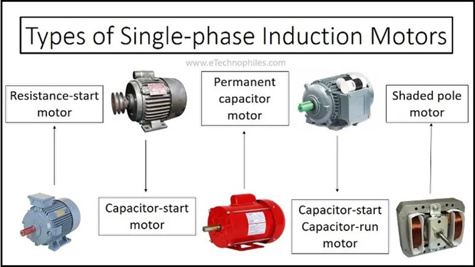
SHADED POLE MOTORS
The shaded pole motor is a type of single-phase motor that offers simplicity, cost-effectiveness, and reliability for low-power applications. It operates without the need for complex windings or starters, making it a popular choice for various small-scale devices.
Construction
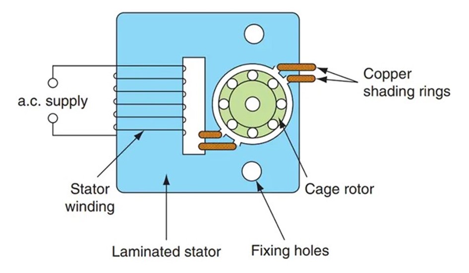
The construction of a shaded pole motor is relatively straightforward. It consists of the following key components:
- Stator: The stator includes the main stator winding and shading coil. The stator is typically made of magnetically conductive material, such as iron, to facilitate magnetic field transfer.
- Rotor: In shaded pole motors, the rotor is a simple squirrel cage design without any windings or additional components.
- Shading Coil: The shading coil, also known as the shading pole, is a shorted copper ring or winding placed around a portion of each stator pole. It creates a time-delayed magnetic field.
Working Principle
The operation of a shaded pole motor is based on the "shaded pole effect." When the single-phase AC current enters the C-core of the motor, it causes the main stator winding to create a pulsating magnetic field. The poles of the motor are divided into two unequal halves, with two "shading" poles created by extending the main stator winding to smaller windings on one of these halves.
As the AC current flows through the stator winding, it "shades" the winded halves by causing the magnetic field to lag through the shaded portion. This is achieved by the shading coil, which creates an opposing magnetic field, effectively slowing down the magnetic flux in the shaded area. As a result, there is an unequal distribution of inductive forces across the rotor, inducing rotation.
The C-core of the shaded pole motor, made of magnetically conductive material, plays a crucial role in transferring the pulsating magnetic field from the main stator winding to the rotor. It ensures that the shading effect takes place and facilitates the rotation of the motor.
Watch the videos showing how shaded pole motors work.
Features and Advantages
Shaded pole motors possess several notable features and advantages, including:
- Simplicity: Shaded pole motors have a straightforward construction, requiring no additional starter circuits, switches, or special windings. This simplicity contributes to their cost-effectiveness.
- Robustness: The absence of complex components like capacitors, commutators, or centrifugal switches enhances the robust nature of shaded pole motors.
- Low Starting Torque: Shaded pole motors have low starting torque, which makes them suitable for applications with low mechanical loads.
- Cost-effectiveness: Shaded pole motors are relatively inexpensive to manufacture, making them popular in small appliances and low-power applications.
Applications
Shaded pole motors find widespread use in various small-scale applications, including:
- Small Fans and Blowers: These motors are commonly found in small extractor fans, ventilation systems, and blowers for cooling and air circulation purposes.
- Appliances: Shaded pole motors power small household appliances like juice extractors, coffee grinders, electric clocks, and early tape-decks.
- Entertainment Devices: They are used in animated models, toy motors, record-player turntables, and other devices that require low starting torque.
- Disposable Motors: Shaded pole motors are often considered disposable due to their low cost, making them more economical to replace than to repair.
SPLIT PHASE MOTORS
Split-phase induction motors are a type of single-phase induction motor widely used in household appliances, small machinery, and moderate starting-torque applications. They feature a unique design with two windings, namely the main winding and the starting winding, which provide the necessary phase difference for motor rotation.
Construction
Split-phase induction motors consist of the following key components:
- Stator: The stator consists of two windings, the main winding and the starting winding. The windings are arranged in a manner that creates a time lag or phase difference of 90 degrees between the alternating currents flowing through them. The main winding has a very low resistance and a high inductive resistance, whereas the starting winding has a high resistance and low inductive resistance.

- Rotor: The rotor is a squirrel cage design, similar to other induction motors, and does not have any windings.
- Starting Mechanism: The starting winding is designed with smaller diameter wire and fewer turns compared to the main winding. This configuration provides more resistance and creates the necessary phase shift for motor starting.
Watch the video about split phase motors to gain a better understanding of how they work.
Working Principle
The operation of a split-phase induction motor is based on the interaction of the two windings and their phase difference. During motor starting, the starting winding, with its higher resistance and lower reactance, produces a phase-shifted magnetic field. This phase difference, typically around 25° to 30°, generates a rotating magnetic field that initiates motor rotation.
Once the motor reaches a percentage of full speed (around 75% of rated speed), a centrifugal switch, usually located on the output shaft, shuts off the starting winding. From that point on, the main winding, with its lower resistance and higher reactance, takes over and sustains motor operation.

Features and Limitations
Split-phase induction motors possess several features and limitations, including:
- Simple and Cost-Effective: Split-phase motors have a relatively simple design, reducing both their cost and complexity. This makes them economical and suitable for various low-to-medium starting-torque applications.
- Moderate Starting Torque: Split-phase motors provide moderate starting torque, making them ideal for applications such as fans, washing machines, oil burners, and small machine tools.
- Overheating Risk: The resistive nature of the starting mechanism in split-phase motors can lead to overheating if operated under high torque or high cycle rates. They are best suited for low torque applications to prevent coil burnout.
Applications
Split-phase induction motors find widespread use in various applications, including:
- Household Appliances: They are commonly used in household appliances like fans, refrigerators, washing machines, and small kitchen appliances.
- Small Machinery: Split-phase motors power small machinery, such as oil burners, small machine tools, pumps, and compressors.
- Moderate Starting-Torque Applications: Their moderate starting torque makes them suitable for applications where a higher starting torque is not required.
Activity
Complete this worksheet and email your answers to your tutor.

What we're covering:
- Single-phase motors - capacitor start motors, capacitor start-capacitor run motors
- Permanent split capacitor (PSC) motors: construction, operating principles
- Features & advantages
- Applications
Capacitor starter motors
If a load requires a starting torque beyond the capability of a split-phase motor, a capacitor-start motor can be used. Capacitor start motors are a type of single-phase induction motor that use capacitors and auxiliary windings to initiate rotation. These motors do not require extra starter circuits or switches, and they employ capacitance instead of resistance to create the necessary phase difference for starting.
Construction and Features
Capacitor start motors consist of a start winding and a capacitor connected in series with it. The start winding is designed with more turns of finer wire compared to the run winding. This configuration allows for increased starting torque and smoother operation during motor start up.
Working Principle
- Starting Phase: When power is supplied to a capacitor-start motor, the start winding, and the main winding are energised. The start winding, along with the capacitor connected in series, creates a phase shift between the currents in the two windings, providing the necessary starting torque.
- Centrifugal Switch Activation: As the motor accelerates, a centrifugal switch located on the output shaft detects the motor's speed. Once the motor reaches a certain speed (around 75-80% of rated speed), the centrifugal switch opens the circuit to the start winding and the capacitor.
- Start Winding Deactivation: When the centrifugal switch opens, the start winding and the capacitor are disconnected from the circuit. The motor continues to run with only the main winding active.
- Main Winding Operation: With the start winding deactivated, the main winding generates the rotating magnetic field required for motor operation.
- Continuous Rotation: The capacitor-start motor continues to accelerate until it reaches its normal operating speed. It runs as a single-phase induction motor with only the main winding active.
- Reversing Capability: Capacitor start motors can be reversed by reversing the connections to either the start winding or the run winding, but not both simultaneously. This capability is achieved using an external reversing switch
Applications
Capacitor start motors find extensive use in various industrial applications that demand higher starting torque. They are well-suited for belt-driven conveyors, large blowers, geared applications, and other general-purpose industrial motor applications. Additionally, they are commonly employed in larger appliances like air conditioners, refrigerators, and pumps.
Advantages and Disadvantages
Compared to other single-phase motor types, capacitor start motors offer improved starting torque and the ability to handle high cycle rates. However, one drawback is their higher cost relative to split-phase motors. Despite this, capacitor start motors are valued for their reliable and efficient performance in applications that require higher starting torque.
Reversing Capability
Capacitor start motors can be reversed by reversing the connections to either the start or run winding, but not both. This reversal can be achieved by using an external reversing switch. The ability to reverse the motor adds flexibility to its application in various scenarios.
Activity
Complete the questions on this worksheet and email the answers to your tutor.
Capacitor start-capacitor run motors
Construction and Features
Capacitor start-capacitor run motors consist of a start winding and a main winding. They are equipped with two capacitors, a start capacitor, and a run capacitor. During start-up, the start capacitor provides a phase shift to facilitate motor starting. These motors feature a centrifugal switch that disconnects the start capacitor once the motor reaches approximately 75% of its rated speed.
The combination of the capacitors creates a phase angle of around 90 degrees, enabling the motor to generate high starting torque. Capacitor start-capacitor run motors are designed with compact size and robust construction to ensure reliable operation. In some cases, external start-winding relays may be used for added safety or to achieve more compact motor designs.

Operating Principle
- Starting Phase: During the starting phase, both the start winding, and the main winding are energised. The start capacitor, along with the start winding, creates a phase difference between the currents, resulting in high starting torque.
- Boosted Start-Up: The start capacitor enhances the motor's start-up performance by aiding rapid acceleration and facilitating the motor to reach its rated speed quickly.
- Run Capacitor Activation: Once the motor reaches its rated speed, a centrifugal switch or potential relay activates the run capacitor. The run capacitor remains connected in parallel with the start capacitor to maintain the desired phase shift during continuous motor operation.
- Continued Operation: With both the start and run capacitors in place, the motor functions as a single-phase induction motor. The combined capacitance of the capacitors ensures efficient operation, improved torque characteristics, and reliable performance.
- Reversing Capability: Similar to other single-phase motors, reversing the direction of a capacitor start-capacitor run motor can be achieved by swapping the connections to either the start winding or the main winding, but not both simultaneously.
Applications
Capacitor start-capacitor run motors are well-suited for a wide range of applications, including:
- Air Compressors: These motors provide the necessary starting torque to drive air compressors efficiently.
- High-Pressure Pumps: CSCR motors are commonly used in high-pressure pump applications, such as water supply systems or industrial processes.
- Vacuum Pumps: They are suitable for powering vacuum pumps, delivering the required starting torque for effective suction.
- 1-10HP Applications: CSCR motors are often found in equipment requiring motor power in the range of 1 to 10 horsepower.
- Industrial Equipment: They are utilised in industrial applications that demand high starting torque and reliable operation, such as conveyor systems, blowers, and geared equipment.
Advantages
- High Starting Torque: Making them suitable for equipment with demanding start-up requirements.
- Efficient Operation: The phase shift introduced by the capacitors ensures efficient motor operation and improved torque characteristics.
- Reliable Performance: These motors are known for their reliability due to their simplistic design and ability to handle moderate-to-high starting torque.
- Reversing Capability: Similar to other single-phase motors, CSCR motors can be easily reversed by swapping the connections to the windings.
- Wide Range of Applications: From industrial equipment to hospital appliances, where high starting torque and quiet operation are essential.
Permanent split motors
Permanent Split Capacitor (PSC) motors, also known as Capacitor Run motors, are a popular type of single-phase induction motor utilised in a wide range of applications. These motors are characterized by the inclusion of a permanent capacitor that remains connected in series with the starting winding, eliminating the requirement for a centrifugal switch. PSC motors are commonly found in HVAC systems, pumps, and blowers, where they exhibit enhanced motor performance and efficiency due to the presence of a run capacitor connected in series with the main winding throughout operation.
Construction
PSC motors are constructed with two windings: the main winding and the auxiliary or starting winding. These windings are designed to have identical resistance and number of turns, ensuring balanced operation. The auxiliary winding is connected in series with a permanent capacitor, forming a continuous circuit. This eliminates the need for a centrifugal switch typically found in other motor types. The inclusion of a permanent capacitor in the series configuration allows the motor to operate seamlessly without the need for manual switching or additional control mechanisms.

Operating Principle
When power is supplied to the motor, the run capacitor and the main winding create a phase shift in the single-phase input. This phase shift produces a rotating magnetic field, allowing the motor to start and run smoothly. The capacitor's size is selected to provide optimum performance and torque at full speed.
Features
- Simplified Circuit: PSC motors eliminate the need for a centrifugal switch due to the permanent connection of the capacitor and windings. The absence of a centrifugal switch enhances reliability and reduces potential maintenance issues.
- Solid-Dielectric Capacitor: PSC motors use a solid-dielectric capacitor, capable of continuous operation in an AC circuit. The capacitor remains in series with the auxiliary winding throughout motor operation.
- Smoother Operation: The capacitor size is selected to provide a more constant strength stator magnetic field while running on load. This results in smoother operation without the characteristic pulsating hum or noise found in other motor types.
- Motor Reversal: PSC motors allow for easy motor reversal by shifting the capacitor from one winding to the other using a reversing switch. This changes the direction of rotation of the stator field, thereby reversing the motor's direction.
- Optimum Performance and Torque: The capacitor size in PSC motors is chosen for optimum performance and torque at full speed. Unlike other motor types, where high starting torque is prioritized, PSC motors sacrifice starting torque for applications with low start torque but increasing load torque with speed.
Applications
PSC motors are well-suited for low-torque applications that require instant reversing, making them ideal for applications like garage doors, gate openers, and fans. They excel in constant-speed operations where high torques are not necessary. Commonly found in HVAC systems, pumps, blowers, and various other applications, PSC motors offer better running torque, higher efficiency, and smoother operation compared to other single-phase motors. Their speed/torque characteristics make them particularly suitable for extract and intake fans, blowers, and similar loads.
Advantages
PSC motors offer simplicity, reliability, high efficiency, and relatively silent running. The absence of a centrifugal switch simplifies the motor's circuitry, making it more reliable. The solid-dielectric capacitor ensures continuous operation, and the smoother running reduces noise and vibration.
Limitations
PSC motors have low starting torque, making them unsuitable for applications with high torque requirements. They are optimized for constant-speed, low-torque applications.
Activity
Complete the questions on this worksheet and email the answers to your tutor.
Activity
Watch these two videos showing how different single phase motors work.

What we're covering:
- Comparison chart highlighting key similarities & differences between shaded pole, split phase, capacitor start, capacitor start/run, and PSC motors.
This session is an opportunity to consolidate all the information from the previous sessions on single-phase induction motors.
Activity
Create a comparison chart to highlight the key differences and similarities between shaded pole, split phase, capacitor start, capacitor start/run, and PSC motors.
Include information such as starting torque, efficiency, reliability, cost, speed control methods, starting mechanisms, applications, compactness and portability, noise level, lifespan or durability, special features, advantages and disadvantages etc.
Your comparison chart should include a minimum of six categories. You may include photos/diagrams, but these are not considered to be 'categories.'
You may choose any format to present your comparison chart, however you must be able to upload it to the Forum, once completed for feedback from other class members and your tutor.

What we're covering:
- Motor selection - motor nameplate information
- Multispeed capability
- Electromagnetic interference
Motor nameplate information
Motors are used in many different ways, and they are powered by a variety of electrical systems. Because of this, there are many different performance ratings and operating characteristics to consider when choosing the right motor for a specific job.
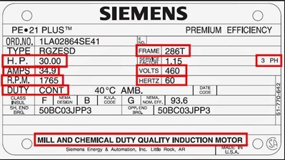
The motor nameplate information is significant in the selection of a motor because it provides crucial specifications and details about the motor. This information helps engineers, technicians, and buyers ensure that the motor is suitable for their specific application and meets the necessary requirements. Some of the key aspects provided on the motor nameplate are listed below.
How many of these can you find on the nameplate above?
Manufacturer
The nameplate includes the name of the company that produced the motor, along with their address and country of origin. It may also include a specific model or production number associated with the motor.
Motor Type
The nameplate specifies the motor type, such as induction motor, synchronous motor, or direct current (DC) motor. Different motor types have distinct characteristics and applications, so selecting the appropriate type is crucial.
Power Rating
The nameplate displays the motor's power rating, usually in kilowatts, kW or horsepower, HP. (1 kW is equivalent to 1.34HP.) The power rating of a motor is crucial in determining whether it can provide the necessary power to drive the intended application. It is important to ensure that the motor's power rating matches or exceeds the power requirements of the equipment or machinery it will be driving.
Activity
Complete this worksheet and email your answers to your tutor.
Voltage Rating
This indicates the operating voltage required for optimal performance as specified by the motor manufacturer. Motors are typically designed with a 10% tolerance for voltage above and below the rated nameplate value. For example, a motor with a rated voltage of 460V can operate between 414V and 506V. If a motor can operate with multiple voltages, this capability will be indicated on the nameplate.
Rated Frequency and Number of Phases (AC Motors)
For AC motors, the nameplate specifies the rated frequency of the power system, which is the number of times an AC voltage wave repeats the same sequence of values within a specified unit of time. The number of phases indicates whether the motor is connected to a single live conductor and neutral (single-phase) or three live conductors (three-phase). Ensuring that the motor's voltage and frequency match the local power supply is essential for proper operation.
Efficiency
Motor efficiency indicates the percentage of electrical energy supplied to the motor that is converted into output shaft mechanical energy. The remaining energy is lost primarily in the form of heat. Higher efficiency motors are generally more energy-efficient and can lead to cost savings over time. Efficiency is calculated by dividing the output power by the input power and multiplying by 100%.
Rated Full Load Speed
The rated full load speed is the actual revolutions per minute (RPM) value listed on the motor nameplate. It indicates the speed at which the motor operates under full load conditions.
Synchronous speed is the theoretical speed at which the rotor would rotate if it could perfectly keep up with the rotating magnetic field.
Slip refers to the difference between the synchronous speed and the actual speed of the motor's shaft rotation. It is typically expressed as a percentage. Slip increases with the load on the motor, providing greater torque.
Insulation Class
This specification on the nameplate indicates the motor's ability to withstand heat generated during operation. It is denoted by a letter, such as Class F or Class H, and ensures that the motor can handle the anticipated temperature rise.
Enclosure Type
The enclosure of a motor refers to its housing or casing, which provides protection and safety. Different applications may require motors with specific types of enclosures to withstand environmental conditions or to meet safety regulations. Common motor enclosures include open drip-proof (ODP), totally enclosed fan-cooled (TEFC), and explosion-proof (XP), among others.
Frame Size
The nameplate provides information on the motor's frame size, which is essential for compatibility with mounting arrangements, such as flanges and bases.
Full-Load Current (FLA)
The full-load current represents the maximum amperage drawn by the motor when operating at maximum torque and horsepower. It is an important rating used to select the appropriate wire size, motor starter, and overload protection devices for the motor. The FLA is usually listed only for the maximum speed in case of multispeed motors.
Service Factor
The service factor represents the periodic overload capacity at which a motor can operate without overheating or sustaining damage when supplied with the rated voltage and frequency. Operating a motor continuously at a service factor greater than 1 may reduce its life expectancy.
Rated Temperature Rise, Insulation System Class, and Rated Ambient Temperature
The nameplate specifies the allowable temperature rise for the motor under full load and at the specified ambient temperature. It also indicates the insulation class and maximum temperature rating. These ratings help ensure the motor operates within safe temperature limits, and they vary depending on the insulation class.
Time Rating
The time rating indicates how long a motor can operate at its rated load and ambient temperature. Standard motors are typically rated for continuous duty, meaning they can operate around the clock without interruption. Some motors may have reduced time ratings for specific applications.
Some additional factors to consider when selecting your motor are:
Multispeed Requirements
Except for the universal motor, single-phase motors are generally single-speed machines. Some applications may however require motors with multiple speed settings to accommodate varying operational needs. Assess whether your task requires a motor with adjustable speed or if a fixed speed motor would suffice. If multispeed capability is necessary, explore motor options that offer speed control methods such as variable frequency drives (VFDs) or multiple windings.
Note the difference between a multispeed motor and a variable speed motor.
- a multispeed motor can operate at more than one set speed.
- a variable speed motor has a controller to provide almost infinite and stepless speed possibilities up to full speed.
Activity
Give some examples of multispeed motors and variable speed motors and share them in the Forum.
Electromagnetic Interference
Certain applications, especially those involving sensitive electronic equipment, may be susceptible to electromagnetic interference (EMI) generated by the motor. Determine if your application requires a motor with low EMI to avoid potential interference issues, then look for motors that are specifically designed to minimise EMI or incorporate features such as shielding and filtering.
Service and Maintenance
Consider the ease of maintenance, availability of spare parts, and the reputation of the motor manufacturer for quality and after-sales support.
Standards and Regulations
Ensure that the selected motor complies with relevant standards and regulations applicable to the specific application or industry.
Budget
Consider the budgetary constraints and balance the required features and performance with the available resources.
Activity
Match the items to the motor nameplate in the image.
- Find out what insulation class ‘F’ means.
- What does the abbreviation for enclosure stand for?
Activity
Watch these three videos from the 10-part series “How to Choose an Electric Motor”.
- How to Choose an Electric Motor | Introduction and Basics
- How to Choose an Electric Motor | Application Criteria (Part 1)
- How to Choose an Electric Motor | Application Criteria (Part 2)
In the third video, three factors are mentioned when selecting a motor for a specific task or machine:
- Speed and torque
- Start or stall torque
- Duty cycle
Write a brief explanation of each factor and explain why it is important in the motor selection process. Email your tutor with your explanation.
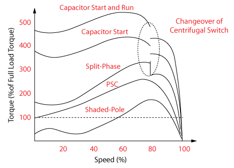
You may be interested to see the various torque-speed curves of different single-phase induction motors shown below. In a single-phase motor the rotating magnetic field effect generated by the stator does not exist until running rpm is reached. Since no starting torque is available, a design mechanism is included to start the motor.

What we're covering:
- Single-phase motor calculations – torque; power; rotational speed; efficiency; power factor & power factor correction.
Torque
Before you begin this lesson watch this video explaining torque.
To calculate torque, we consider the force applied and the distance from the axis of rotation. The formula for torque is τ = F x r, where F is the force and r is the distance. It is derived from the principle that torque is the product of force and the perpendicular distance from the axis of rotation.
Let’s say we’re using a 0.5m long wrench to tighten a wheel nut, and we need to lean on the far end of the wrench with a force of 50 Newtons to do it up tightly. Multiplying the two numbers gives us the required torque figure in Newton metres:
50 (N) x 0.5 (m) x = 25 Nm of torque.
Torque is a vector quantity, meaning it has both magnitude and direction. The right-hand grip rule helps us determine the direction component of the torque vector.
To apply the right-hand grip rule, follow these steps:
- Extend your right hand and curl your fingers in the direction of the force applied.
- Imagine your thumb pointing upward from the palm of your hand
- The direction in which your thumb points represents the direction of the torque vector.
- By using this rule, you can determine the direction of the torque vector based on the direction of the applied force. It is a commonly used technique in physics and engineering to establish the orientation of torque in rotational systems.
Now let’s consider torque in relation to motors. Torque represents the ability of the motor to rotate a load or perform mechanical work. In simpler terms, torque is the force that causes an object to start moving or change its rotational speed.
The formula relating torque (T), power (P), and rotational speed (N) of a motor is:

The formula is derived from the work-energy relationship in rotational systems. Work done (W) in one revolution is equal to the torque multiplied by the angle of rotation (θ), and it is also equal to the product of force and distance moved (2πrF). (Go back to the video if necessary.)
Combining these relationships, we get W = T x θ = 2πrF, and by dividing both sides by time (t), we get P = W/t.
Since one revolution takes time t = 60/N seconds, we can substitute and rearrange to get T = (60P) / (2πN).
This formula allows us to determine the torque required or produced by a motor.
Example:
A motor with a power output of 1000 kW is operating at a speed of 1500 RPM. Calculate the torque produced by the motor.
Solution:

Activity
Determine the torque produced by a motor operating at a speed of 900 RPM with a power input of 400 watts. (Remember to work in kW!)
Understanding torque is crucial when selecting a motor for applications that involve lifting heavy objects, driving conveyor belts, or operating machinery that requires significant rotational force.
For a single-phase motor the rotating magnetic field effect generated by the stator does not exist until running rpm is reached. Since no starting torque is available, a design mechanism is included to start the motor. These are the various Torque-Speed Curves of Different Single-Phase Induction Motors:

Power, speed and torque relationship
It's important not to confuse torque with power and energy. Torque is about the force that causes rotation, while power is the rate at which work is done or energy is transferred. In engines, power is often calculated using torque and rotational speed.

Example:
A load requires a torque of 2 Nm to be rotated at a speed of 1800 RPM. Determine the power required by the motor to meet this torque requirement.
Solution:
Torque (T) = 2 Nm, and Speed (N) = 1800 RPM
Using the formula P = (2π x N x T) / 60: P = (2π x 1800 x 2) / 60 P ≈ 188.5 watts
Activity
Efficiency
The efficiency of a motor refers to how effectively it converts electrical (input) power into useful mechanical (output) power. A higher efficiency value indicates that a larger proportion of the electrical power supplied to the motor is being converted into useful mechanical work, resulting in reduced energy losses and lower operating costs. Efficient motors also tend to have better performance characteristics and longer operational lifetimes.
Motor efficiency (symbolized by η and pronounced eta) is typically expressed as a percentage and represents the ratio of output power to input power. To express the efficiency as a percentage multiply this ratio by 100.

where:
- η is the efficiency of electric motor
- Pm is the mechanical output power, determined by Pm = Tω (T is the output torque, and ω is the angular velocity of the output)
- Pe is the input electrical power, determined by Pe = IV (V and I are the input current and voltage)
Activity
Losses in Induction Motors
If the motor has 100% efficiency all electrical power is converted to mechanical energy (Pe = Pm). However such motors do not exist. Mechanical power output is always lower than the electrical power input, as energy is lost during the conversion process in various forms, such as heat, friction, ohmic losses, and noise.
Motor losses are the difference between the input and output power.

Motor efficiency is influenced by various factors, including the motor design, type, size, quality of materials, operating conditions, and load conditions. Regardless of motor type, the described losses cannot be completely designed out.
Power losses in motors occur mainly due to:
- Air friction or windage occurs when the rotor and fan are rotating, creating resistance and consuming some power.
- Mechanical friction arises from the bearing surfaces in contact, causing frictional losses.
- Core losses, also known as iron losses, result from the energy required to magnetise the core of the motor, leading to energy loss.
- Resistance losses occur due to the flow of current in the resistive stator and rotor windings. These losses are often referred to as copper losses or I²R losses.
Measuring input power and output power
Input Power, Pe
- Wattmeter: a specialised device connected in line with the motor's power supply that provide the input power reading in watts (W).
- Clamp-on Ammeter: Measures the current flowing into the motor. By combining the current measurement with the measured voltage across the motor terminals, input power may be calculated using Pe = VI.
- Power Analyser: Connect a power analyser to the motor's power supply, and it will provide readings for voltage, current, power factor, and other parameters, allowing you to determine the input power.
Output Power, Pm
- Calculate using the formula: Pm = T x ω
(Torque, T, measured in Nm.)
(Angular velocity, ω, measured in radians/second.)
- Dynamometer: A device that applies a load to the motor's output shaft then measures the torque and rotational speed to calculate the output power.
- Prony Brake: A device that applies an adjustable braking force to the motor's output shaft, causing it to slow down. Output power can be calculated by measuring applied force and the resulting decrease in rotational speed.
- Direct Measurement: In certain applications, mechanical power output can be measured directly using specialised instruments such as a power meter or a dynamometer connected to the driven load.
Note: For a motor operating under rotational motion, the output power can be calculated using the formula:
Output Power, Pm = 2πNT/60
(where N is rotational speed in RPM, and T is torque in Nm)
or Output Power, Pm = 2πNT
(where N is rotational speed in revolutions per second, and T is torque in Nm)
It is important to note that this formula may not be applicable to all types of motors or situations. Different types of motors, such as linear motors or other specialised motors, may have different formulae for calculating output power based on their specific characteristics and operating principles.
Activity
Most electric motors are designed to operate within a load range of 50% to 100% of their rated load. The maximum efficiency of a motor is typically achieved near 75% of its rated load.
Operating motors at loads below 50% can lead to a significant decrease in efficiency. The efficiency range can vary for different motors, with larger motors often having a broader range of good efficiency.
Overloading a motor can cause overheating and reduce its efficiency. Motors are designed with a service factor, which indicates the degree to which they can be overloaded for short periods without sustaining damage.
It is important to avoid operating motors above their rated load continuously, as this can decrease efficiency and shorten motor life. Operating under low voltage, high ambient temperature, or with impaired cooling can also impact efficiency.
Power factor
Power factor is a measure of how effectively a motor utilises the electrical power supplied to it. It is denoted by λ (Lambda) and has no units. PF expresses the ratio of true power used in a circuit to the apparent power delivered to the circuit, with values ranging from 0 to 1, or as a percentage, where a higher value indicates better power utilisation. A 96% power factor demonstrates more efficiency than a 75% power factor.
Power factor (PF) is the ratio of working power, measured in kilowatts (kW), to apparent power, measured in kilovolt amperes (kVA). Apparent power, also known as demand, is the measure of the amount of power used to run machinery and equipment during a certain period. It is found by multiplying (kVA = V x A). The result is expressed as kVA units.

If the current and voltage are of sine waveform and at a phase angle of 𝜑 to each other then,
p.f. = cos 𝜑
Power factor and efficiency
Make sure you are clear about the differences between these two concepts.
Power factor refers to the ratio of real power to apparent power in an AC electrical system, indicating the efficiency of power utilisation and the presence of reactive power. Efficiency, on the other hand, measures how effectively a device or system converts input power to useful output power, accounting for losses in the conversion process. While power factor relates to overall power utilisation efficiency, efficiency specifically focuses on the conversion efficiency of a device or system, such as a motor, in converting input power to useful output power.
Calculating power factor
One method to measure the power factor of a circuit, is to use a wattmeter, ammeter, and voltmeter. Connect the wattmeter in series to measure the real power (P). Measure the current (I) with an ammeter and the voltage (V) with a voltmeter. Calculate the apparent power (S = V x I) and divide the real power by the apparent power to find the power factor (PF = P / S).
Alternatively, you can use a power meter or power analyser that can measure both the real power (P) in kW and apparent power (S) in kVA of the circuit. The power factor (PF) can then be calculated as the ratio of real power to apparent power: PF = P / S.
Power factor correction
Power factor is an important consideration because a small power factor indicates inefficient power usage, which can have several implications:
- Heat damage to insulation and other circuit components.
- Reduction in the available useful power for equipment and machinery.
- The need for increased conductor and equipment sizes to compensate for lower power factor.
- Increased costs in power distribution systems, as lower power factor requires higher currents to supply the loads.
Power factor correction involves taking steps that help reduce the reactive power and enhance the overall efficiency of the system. Here are some common methods:
- Power Factor Correction Capacitors: Install power factor correction capacitors in parallel to the motor. These capacitors supply reactive power locally, offsetting the reactive power drawn by the motor and improving the power factor. Capacitors act as reactive power generators, reducing the burden on the electrical system.
- Sizing and Design of Motors: Select motors that are appropriately sized for the load requirements. Oversized motors tend to have lower power factors. By accurately sizing the motor, you can ensure it operates closer to its optimal efficiency and power factor.
- Proper Load Management: Avoid operating motors at partial loads whenever possible. Motors tend to have lower power factors at lower loads. If you have multiple motors, load management techniques such as sequencing or speed control can be employed to ensure motors operate at closer to full load.
- Minimise Voltage Drop: Maintain adequate voltage levels at the motor terminals to reduce voltage drop. Voltage drop can negatively impact the motor's power factor. Proper wiring, adequate conductor sizes, and minimising the distance between the motor and the power source can help reduce voltage drop.
Power factor correction helps reduce electrical losses, improve energy efficiency, and optimise the power distribution system. It is particularly important in industrial settings where motors consume a significant amount of power.
Activity
Complete this worksheet and email it to your tutor when you have finished.

What we're covering:
- Motor evaluation & fault diagnosis: visual inspection; verifying motor performance against nameplate specifications; motor testing.
Motors must be operated to meet the safety standards of the NZ Wiring Rules AS/NZS 3000.
A fault with a motor or electrical system means there is a problem or malfunction that affects how the motor works. It can show up in different ways like strange sounds, vibrations, less power, overheating, electrical problems, or physical damage.
Identifying motor faults is crucial for maintaining efficient electrical systems, since:
- Motor faults can reduce efficiency, increase costs, and cause unexpected breakdowns.
- Faulty motors pose safety risks, such as fires or electric shocks.
- Unresolved faults can lead to further damage and premature equipment failure.
- Poor motor performance hinders productivity and quality.
Promptly addressing motor faults ensures optimal efficiency, reliability, safety, and productivity.
Common faults that can occur in single-phase motors include:
- Overload damage: Excessive load or operating conditions beyond the motor's capacity can lead to damage, such as overheating or mechanical stress.
- Open-circuit faults: Breaks or discontinuities in the motor's electrical circuits can result in loss of power or complete failure.
- Failure of the starting circuit: Issues with the starting circuit, including faulty switches or capacitors, can prevent the motor from starting or cause it to start slowly.
- Capacitor failure: If the motor is equipped with capacitors, their failure can lead to improper motor operation or failure to start.
- Short-circuit in the windings: Short-circuits within the motor's windings can cause abnormal currents, overheating, and potentially damage the motor.
- Open-circuit rotor: Breaks or faults in the rotor circuit can prevent proper motor operation or cause it to run at reduced performance.
- Insulation failure to the frame: Insulation breakdown between the motor windings and the motor frame can result in electrical faults, including short-circuits or ground faults.
- Universal motor brush failure: In universal motors, the brushes that make contact with the commutator can wear out or become damaged, affecting motor performance.
- Bearing wear or failure: Bearings in the motor can experience wear over time or fail prematurely, leading to increased friction, noise, and potential damage to the motor.
Proper maintenance, periodic inspections, and timely troubleshooting can help prevent or address these issues, ensuring smooth operation and extending the lifespan of the motor.
Procedure
A. Visual Inspection
Conduct visual fault finding
- Examine the motor's general appearance for visible burns or damage on the body, cooling fan, or shaft.
- Rotate the motor shaft manually to check the bearing's condition. Smooth rotation indicates a good bearing, while resistance suggests a need for replacement.
- Inspect the motor casing for physical damage, cracks, or signs of overheating.
- Check for loose connections, corroded terminals, burnt wiring, damaged insulation, worn-out parts, or any abnormal physical characteristics.
- Inspect the motor's cooling system, such as fans or vents, for blockages or obstructions.
- Look for signs of excessive vibration, noise, or abnormal operation.
- Document any observed faults or abnormalities for further analysis.
Gather information
- Talk to the customer or the person operating the motor to gather background information on when the problem occurred and any observations at the time of the fault. This can assist in identifying the problem more quickly.
Run the motor and perform sensory checks
- Start the motor (if possible) and visually inspect for unusual states, such as excessive sparking, smoke, loose connections, or equipment damage.
- Listen for unusual noises, including worn bearings, rubbing metal parts, vibration from loose mechanical parts, excessive speed, or magnetic hum.
- Feel the motor casing and bearing housing for abnormal temperature. Use a thermometer if surfaces are too warm to touch safely.
- Smell for burnt varnish or the distinct odour of ozone, which indicates insulation breakdown or electrical arcing.
Follow a step-by-step diagnostic approach
- Follow an orderly sequence for diagnostic fault finding.
- Check motor supply availability and reset overloads if the motor won't start before proceeding.
- Activate control devices to observe the motor's response when running.
- Compare measured readings with known and nameplate data.
- Use a tachometer to check the motor speed.
Shutdown and conduct further visual checks
- Shutdown the motor and isolate the supply circuits.
- Carry out additional visual checks to distinguish between mechanical and electrical problems.
- Spin the motor shaft to check for smooth running and alignment.
- Inspect motor ventilation, fastenings, casing, coupling mechanism, and alignment with the load.
- Check centrifugal mechanisms, brushes, slip rings, etc., for wear and looseness.
To test the rotor of an induction motor without removing it, connect an extra low voltage AC supply to the input terminals and monitor the current with an ammeter. Slowly rotate the motor shaft and observe any current variations. If the current changes by more than 3%, it indicates potential rotor issues. In such cases, remove the rotor from the motor and inspect it for cracks in the end rings and bars. Replace the faulty rotor with a new one as necessary.
Visual fault finding provides initial clues about potential problems, but further testing is often required for accurate diagnosis. By comparing test results with the nameplate specifications and inspecting the motor visually, you can identify areas where the motor's performance is not meeting the desired standards.
Activity
Try these questions to check your understanding of this section. Email your answers to your tutor.
- During a visual inspection of a motor, you notice excessive vibration and noise. What could be potential causes of these issues, and how would you further investigate them?
- A motor's casing feels unusually hot to the touch during operation. What could be the possible reasons for this, and what steps would you take to address the problem?
- After performing a visual inspection and running the motor, you find that the motor speed does not match the nameplate specifications. What are some potential reasons for this discrepancy, and how would you further investigate to identify the root cause?
B. Verifying Motor Performance Against Nameplate Specifications
The motor nameplate provides valuable information that will help to ascertain the true health of the motor. Examine the name plate thoroughly and verify the stated values:
- Voltage Measurement: Measure the voltage supplied to the motor using a voltmeter. Compare this value with the rated voltage specified on the motor's nameplate. A significant deviation may indicate a voltage-related issue affecting motor performance.
- Current Measurement: Use an ammeter to measure the current drawn by the motor during operation. Compare the measured current with the rated current specified on the nameplate. Significant variations may suggest motor overload or other electrical problems.
- Power Measurement: Calculate the power consumed by the motor by multiplying the measured voltage and current. Compare the obtained power with the rated power mentioned on the nameplate. Deviations could indicate inefficiencies or other issues affecting performance.
- Speed Measurement: Measure the rotational speed of the motor using a tachometer or an RPM (revolutions per minute) meter. Compare the measured speed with the rated speed indicated on the nameplate. Significant differences may suggest motor slippage or issues with the motor's control mechanisms.
- Efficiency Calculation: Calculate the motor's efficiency using the formula: Efficiency (%) = (Output Power / Input Power) x 100. Determine the output power by multiplying the torque and rotational speed and calculate the input power by measuring voltage and current. Compare the calculated efficiency with the rated efficiency specified on the nameplate. Deviations may indicate losses or inefficiencies within the motor.
- Operating temperature: Measure the ambient temperature, add 40°C to it (as most motors are designed to operate at that temperature above ambient), measure the temperature of the motor using an infrared thermometer or temperature probe, compare the measured temperature with the recommended operating temperature or maximum allowable temperature stated on the motor's nameplate. If the measured temperature exceeds the specified range, there may be an issue with overheating or motor performance.
Thermal Overloads
A thermal overload is a protective device used in motors to prevent damage from overheating. When the temperature exceeds a certain threshold, the thermal overload triggers and interrupts the motor's electrical circuit, acting as a safety mechanism to safeguard the motor. It helps prevent damage caused by long-term overcurrent, which can be caused by various factors such as mechanical faults or overloads. If the thermal overload frequently trips even when the motor is running at its rated speed and torque, it could indicate excessive current flow due to short circuits in the windings or a malfunctioning overload device. It is important not to simply reset the thermal overload without identifying and addressing the underlying cause.
Activity
Try these questions to check your understanding of this section. Email your answers to your tutor.
- Why is it important to measure the current drawn by the motor during operation?
- How can you calculate the power consumed by the motor?
- What does it mean if the measured temperature of the motor exceeds the recommended operating temperature or maximum allowable temperature stated on the nameplate?
- Why is it necessary to measure the motor's rotational speed?
C. Motor Testing
Visual inspections are limited to detecting observable faults in motors. However, to identify faults that cannot be easily observed, additional tests are employed. These tests include:
Earth Continuity and Resistance Test
Ensuring proper earthing continuity in a motor is crucial for maintaining electrical safety and preventing potential hazards caused by faults or improper grounding.
- Prepare the Multimeter: Turn off the power to the motor and set the multimeter to measure resistance (Ω). Insert the black test lead into the COM port and the red lead into the jack marked Ω.
- Measure Motor Casing Resistance: Using the multimeter, connect one probe to the motor's casing (body) and the other probe to a known earth point, such as a ground wire or a metal structure connected to earth.
- Check Resistance Value: A properly grounded motor should exhibit a resistance reading of not more than 0.5 ohms. If the resistance reading exceeds 0.5 ohms, it indicates a faulty motor with a poor earth connection.
- Test Earthing Continuity: The earthing continuity test ensures that there is a good connection between the motor's earth pin and its casing. It is performed on Class I appliances. The goal is to have a resistance of not more than 1 ohm to ensure the protective earth circuit functions correctly.
- Check Protective Earth Conductor: Verify the continuity of the protective earth conductor between the earth pin of the motor's plug and the earth contact. Also, check every outlet, cord sets, cord extension sets, EPODs, and PRCDs for continuity.
- Flex and Strain Test: To detect broken strands or loose connections, perform a flexing and straining test at points of entry and clamping points. Apply a reasonable combination of push/pull and rotary movements to the motor while checking for any interruptions in the earthing continuity.
It is advisable to conduct the earthing continuity test in conjunction with insulation testing for a comprehensive evaluation of the motor's safety and performance.
Testing Insulation Resistance
Regular insulation testing helps identify insulation breakdown or deterioration, which can lead to electrical faults or hazards. You can find detailed instructions and expected results for different types of appliances in Section 2.3.3 Testing and Appendices D and E of the ASNZS 3760-2010 standard.
To test the insulation resistance of a motor, follow these steps:
- Select the Test Voltage: Set your insulation resistance tester or megohmmeter to 500V.
- Measure Motor Winding to Earth: Using the insulation tester, assess the insulation resistance between the motor winding and the earth. Check the connections for phases C-to-E, S-to-E, and R-to-E. (S is Start Winding, R is Run Winding, and C is Common connection between them.)
- Evaluate Insulation Resistance Value: An electric motor in good condition typically has a minimum insulation resistance value of around 1 MΩ. Meeting or exceeding this value indicates satisfactory insulation. However, if the measured insulation resistance is significantly lower or indicates an open circuit, it signals a fault in the motor's insulation that requires attention.
If the insulation resistance readings are low, then the usual problem is moisture in the windings. This could lead to tracking and an electrical flashover. Drying out the motor usually restores the high insulation resistance values.
Power Supply Test
To ensure proper operation of a motor, it is important to verify that the motor is receiving the correct voltage. To perform the power supply test:
- Turn the power to the motor ON and set the multimeter to measure AC volts.
- Insert the black test lead into the COM port and the red test lead into the V jack of the multimeter.
- Connect the two probes in parallel across the load, ensuring the negative (black) probe is grounded and the positive (red) probe is connected to a positive point in the circuit.
- Measure the voltage and ensure it falls within the expected range of approximately 230V. (Within 10% of rated value.)
AC Motor Winding Resistance Testing
By measuring the resistance using a multimeter, you can identify potential issues with the motor's windings.
To conduct AC motor winding resistance testing:
- Use a multimeter to measure the motor winding resistance or ohms reading.
- Since single-phase motors have three terminals (S, C, and R), measure the winding resistance as follows: C to S, C to R, and S to R.
- The measured value of S to R should be equal to the sum of C to S and C to R: S-R value = C-S value + C-R value.
- Keep the following rules in mind for single-phase motors.
- The highest resistance reading should be between S and R.
- The lowest resistance reading should be between C and R.
- The resistance reading between C and S should fall between the values of S to R and C to R.
Windings should have high insulation resistance to earth and between windings and therefore, very low leakage currents.
Testing the Running Amperage
Running amps testing is a crucial procedure to assess a motor's performance under load. By measuring the full load amps (FLA) using a suitable meter or clamp-on meter and comparing it with the motor's nameplate FLA, deviations can be detected, indicating potential motor issues.
To perform the test, turn off the power initially, set the multimeter to measure AC current, and connect the probes in series with the load. Then, turn on the power and take a reading.
Testing the Capacitor
When testing a capacitor, it is important to follow proper procedures based on the voltage rating of the capacitor.
Steps for testing a low-voltage capacitor using an insulation tester:
- Safety precautions: Ensure the appliance is isolated and disconnected. Proper safety measures must be followed when working with capacitors, as they can store electrical energy and present a risk of electric shock. Before testing, remove and discharge the capacitor using a 20 K 5 W resistor to prevent any residual charge.
- Visual inspection: Inspect the capacitor visually for signs of deterioration, such as rust-coloured streaks or cracked insulation.
- Insulation resistance testing: Set your insulation tester to the 250V range, suitable for 400V rated capacitors. Connect the test leads to the capacitor terminals and observe the displayed resistance value.
- Resistance changes from 0 to infinity: Indicates a good capacitor.
- Resistance changes to zero: Indicates a short-circuited capacitor.
- Resistance does not change from infinity: Indicates an open-circuited capacitor.
- Discharge the capacitor: Once the insulation resistance testing is complete, discharge the capacitor again using the 20 K 5 W resistor.
- Capacitor charging test: Charge the capacitor to approximately half of its scale while still connected to the test leads. After around 30 seconds, reconnect the leads and observe the value displayed:
- Value starts at about half scale and charges: Indicates a good capacitor.
- Value starts at zero and charges: Indicates a faulty capacitor.
A final word on safety…
When conducting fault finding procedures using instruments, it is essential to observe safety precautions. Here are some important considerations to keep in mind:
- When temporarily disconnecting wires or leads, ensure they are clearly marked for proper reconnection.
- When measuring a coil with low resistance, ensure that the test leads are securely connected and take temperature into account.
- Use test instruments correctly by inserting them in the circuit as instructed, such as placing an ammeter in series and a voltmeter across the circuit.
- It is advisable to have a combination of instruments as no single meter can fulfil all requirements.
- Never use an ohmmeter or multimeter selected for measuring resistance when voltage is present in the circuit.
Activity
Try these questions to check your understanding of this section. Email your answers to your tutor.
- During the earth continuity and resistance test, you measure a resistance reading of 1.2 ohms between the motor casing and a known earth point. What does this reading indicate, and what should be your next course of action?
- When performing insulation resistance testing on a motor winding, you measure an insulation resistance value of 500 kΩ. Is this reading satisfactory, and what action should be taken based on this result?
- During the power supply test, you measure a voltage reading of 210V across the motor load. Is this reading within the expected range, and what could be the potential consequences of this voltage deviation?

What we're covering:
- Connecting and reversing single-phase motors
- DOL starters
Connecting single phase motors
When connecting single-phase motors, it is essential to follow the guidelines provided by ASNZS 3000 – 2018. This standard emphasizes the importance of devices for isolation and switching. Specific sections of the standard, such as 4.14 for transformers and 4.15 for capacitors, must be thoroughly understood.
Single-phase motors require specific wiring configurations to start and operate correctly. It is crucial to refer to the motor's documentation for precise guidance when connecting single-phase motors since this will vary depending on the motor's design and manufacturer's instructions.
A general outline for connecting single-phase motors is given below, however your tutor will demonstrate techniques in the workshop, and you will be given opportunities under the guidance of your tutor, to practice this yourself.
Safe motor connection:
- Practice safe and correct working practices, including conducting a risk assessment to identify potential safety hazards.
- Verify the adequacy of the electrical supply by assessing factors such as supply capacity, voltage stability, electrical interference, starting and running current capacity, current capacity for continuous or intermittent load, cleanliness, insulation resistance, and equal winding resistance.
- Ensure that the motor is suitable for the operating environment and visually inspect it and auxiliary equipment for any damage sustained.
- Remove any protective coatings or coverings, if applicable, and ensure the machine is properly lubricated.
- Confirm the suitability of the foundation, ensuring it is flat, solid, rigid, and level.
- Obtain installation and commissioning details from specifications, drawings, and manuals before starting the work.
- Securely position the motors and align shafts to match the coupling.
- Plan the electrical connections, including cabling, glands, terminations, and accessories.
- Install control and protective equipment correctly, including guards and covers.
- Test to confirm the safety of the motors and control equipment.
- Conduct commissioning tests, both off-load and on-load, to check the direction of rotation, vibration, temperature rise, and current draw.
- Perform a commissioning inspection and document the test results.
- Use appropriate hand and/or power tools for the job and ensure they are well-maintained and inspected for wear or damage prior to use.
Watch the videos which discuss how to connect single phase motors.
- How to connect a single-phase motor and identify each winding lead?
- Single Phase Electric Motor Wiring Tutorial: Baldor, WEG, Leeson
- How to Connect a Single-Phase Motor
Different types of single-phase motors have specific wiring configurations for their proper operation. Connection methods for common single-phase motors are summarised below:
Shaded-Pole Motor
- Single winding with a shading coil or copper shading ring.
- Shading coil induces a time-delayed rotating magnetic field.
- The rotating field initiates motor rotation.
- Simple design, self-starting, but provides low torque for low-power applications.
Split-Phase Motor
- Two windings: start winding and run winding.
- Start winding is connected in series with a centrifugal switch and a starting capacitor.
- Start winding and capacitor provide initial starting torque.
- Centrifugal switch opens at a certain speed, disconnecting start winding and capacitor.
- Run winding remains connected for continuous operation.
Capacitor-Start Motor
- Two windings: start winding and run winding.
- Starting capacitor is in series with the start winding.
- Start winding and capacitor energised during start-up for extra starting torque.
- Centrifugal switch opens at a certain speed, disconnecting start winding and capacitor.
- Motor continues running with only the run winding connected.
Capacitor-Start-Capacitor-Run (CSCR) Motor
- Combination of capacitor-start and capacitor-run motor designs.
- Utilizes two capacitors: a starting capacitor and a running capacitor.
- Starting capacitor provides high starting torque.
- Running capacitor remains connected during operation to improve motor performance.
- No centrifugal switch: both capacitors remain connected for starting and running.
Permanent Split Capacitor (PSC) Motor
- Two windings: main or run winding and auxiliary winding.
- Auxiliary winding connected in parallel with a non-polarised capacitor.
- Auxiliary winding provides additional starting torque.
- No centrifugal switch: auxiliary winding and capacitor remain connected during operation.
- Widely used in various applications for simplicity and reliable operation.
Activity
Match the letters and numbers to the correct diagrams.
DOL starters
While this course has focused only on single-phase motors it is useful to learn a little about the Direct-On-Line Starter, or Direct Starter. DOL starters are primarily used for three-phase motors, as they are designed to handle the characteristics and requirements of these motors. For single-phase motors, alternative starting methods such as capacitor-start, capacitor-run, or other specialized starters are typically employed.
Components of a DOL starter include a contactor, an overload relay, and start/stop push buttons. The contactor is an electromagnetic switch that controls the power supply to the motor. The overload relay protects the motor from overload conditions by sensing the current and tripping if it exceeds the set limit. The start and stop push buttons are used to manually initiate and halt the motor's operation.
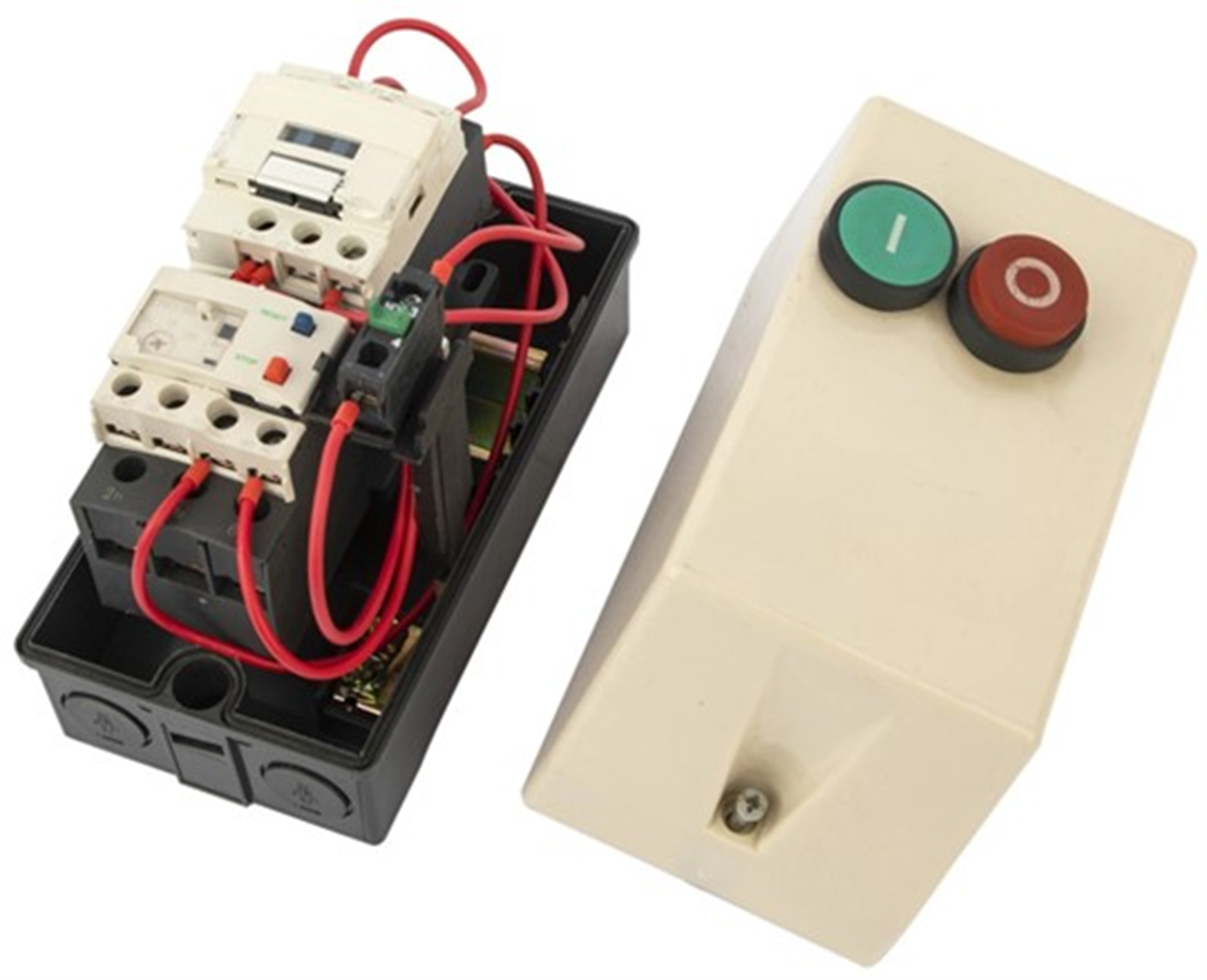
When the DOL starter is activated by pressing the start button, the contactor closes, allowing the power to flow directly to the motor. The motor starts immediately, drawing a high starting current due to the absence of any reduced voltage or soft-start mechanism.
Consult the AS/NZS 3000:2018 Wiring Rules, regarding the wiring and connections for a DOL starter. The power supply lines (active, neutral, and earth) are connected to the input terminals of the contactor, while the motor is connected to the output terminals. The overload relay is connected in series with the motor to monitor the current and provide protection.
Reversing single phase motors
Watch the videos which discuss how to reverse single phase motors.
- Reversing single phase induction motors
- Single phase motor reverse forward rotation with running winding reverse method
Once started, a single-phase induction motor will happily run in either direction. At the core of an induction motor is a rotor made of permeable iron and an aluminum circuit winding. The motor follows the magnetic field it senses. To reverse it, we need to change the direction of the rotating magnetic field produced by the main and starter windings. This can be accomplished by reversing the polarity of the starter winding.
Some motors are labelled as non-reversible, indicating that the necessary wires are housed within the motor, making it challenging to access and reverse them. In such cases, it is advised not to proceed.
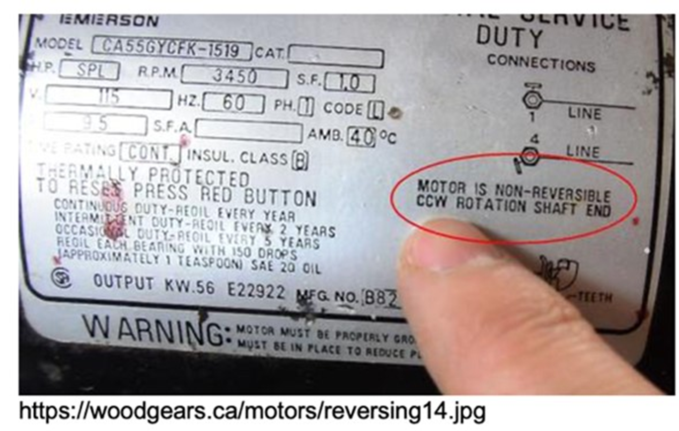
If a motor is reversible, follow the manufacturer's instructions provided with the motor to determine which wires need to be changed:
- Gain access to the motor's terminal connections by removing the end caps or opening the junction box.
- Identify the wires that need to be reversed based on the manufacturer's instructions.

- Use a flathead screwdriver or needle-nosed pliers to switch the terminals to which the identified wires are attached.
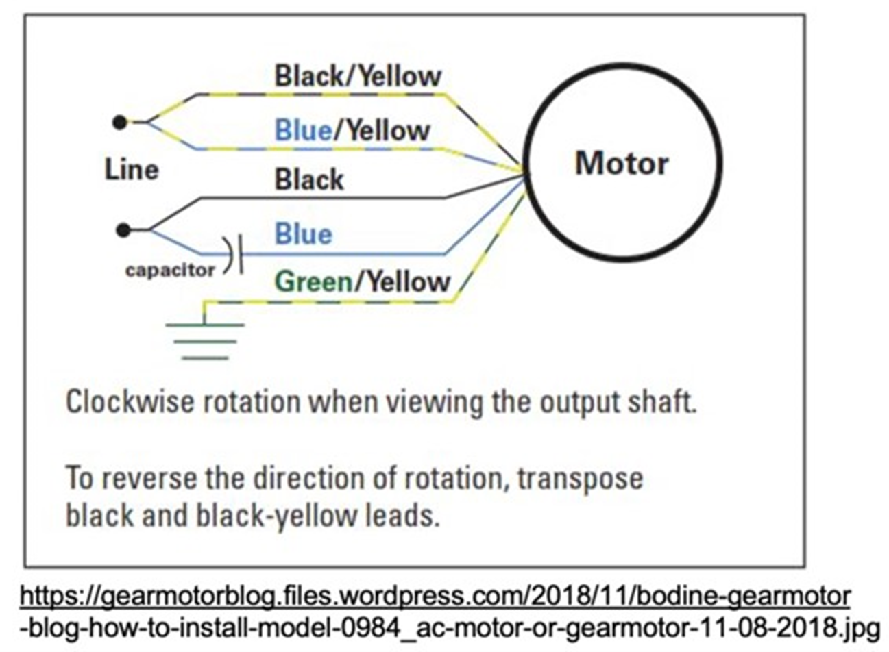
- Replace the end cap or close the junction box.
- Restore power to the circuit and test the motor to ensure the magnetic field has switched, resulting in the motor spinning in the opposite direction.
Capacitor start motors use a capacitor connected to either the L or N wire to create a slight phase shift in the magnetic field of the windings. Reversing the supply to the start winding (L or N) is like reversing two leads in a three-phase motor.
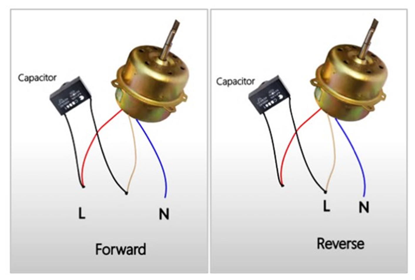
To reverse the direction of a single-phase capacitor induction run motor, you need to change the polarity of the rotating magnetic field created by the main and starter windings (or auxiliary winding). This is done by swapping the connections at either end of the starter or auxiliary winding. In some cases, only the auxiliary winding is involved in the reversal, while in others, a combination of winding, switch, and capacitor is used. The order of the switch and capacitor doesn't matter as long as they are connected in series.
Shaded pole motors are direction-specific and cannot be easily reversed by simply reversing leads or polarity. Reversing may require motor rewinding or replacement.
The reversal methods mentioned in the following table are general guidelines only. Specific wiring configurations and reversal procedures may vary depending on the motor model and manufacturer.
| Motor Type | Reversal Method |
|---|---|
| Shaded Pole Motors | Reversal requires modifying winding connections or external devices. |
| Split-Phase Motors | Interchange connections of main or auxiliary winding |
| Capacitor-Start Motors | Interchange connections of main winding or starting capacitor. |
| Capacitor-Start/Run Motors | Interchange connections of main winding or starting capacitor. |
| PSC (Permanent Split Capacitor) Motors | Interchange connections of main winding or capacitor |
Activity
Select the correct answer for the questions below.
Well done on reaching the end of Module 5. Your next step is passing the Capstone assessment and then you will have your Level 3 Certificate!